EP1362771B1 - Composite car body part - Google Patents
Composite car body part Download PDFInfo
- Publication number
- EP1362771B1 EP1362771B1 EP20030009954 EP03009954A EP1362771B1 EP 1362771 B1 EP1362771 B1 EP 1362771B1 EP 20030009954 EP20030009954 EP 20030009954 EP 03009954 A EP03009954 A EP 03009954A EP 1362771 B1 EP1362771 B1 EP 1362771B1
- Authority
- EP
- European Patent Office
- Prior art keywords
- body part
- vehicle body
- part according
- outer skin
- thermal expansion
- Prior art date
- Legal status (The legal status is an assumption and is not a legal conclusion. Google has not performed a legal analysis and makes no representation as to the accuracy of the status listed.)
- Expired - Fee Related
Links
Images
Classifications
-
- B—PERFORMING OPERATIONS; TRANSPORTING
- B62—LAND VEHICLES FOR TRAVELLING OTHERWISE THAN ON RAILS
- B62D—MOTOR VEHICLES; TRAILERS
- B62D29/00—Superstructures, understructures, or sub-units thereof, characterised by the material thereof
- B62D29/04—Superstructures, understructures, or sub-units thereof, characterised by the material thereof predominantly of synthetic material
- B62D29/043—Superstructures
-
- B—PERFORMING OPERATIONS; TRANSPORTING
- B62—LAND VEHICLES FOR TRAVELLING OTHERWISE THAN ON RAILS
- B62D—MOTOR VEHICLES; TRAILERS
- B62D25/00—Superstructure or monocoque structure sub-units; Parts or details thereof not otherwise provided for
- B62D25/06—Fixed roofs
Description
Die Erfindung betrifft ein Fahrzeug-Karosserieteil, insbesondere ein Fahrzeugdach, nach dem Oberbegriff des Patentanspruches 1.The invention relates to a vehicle body part, in particular a vehicle roof, according to the preamble of claim 1.
Ein derartiges Fahrzeug-Karosserieteil ist beispielsweise aus der
Insbesondere werden bei bekannten Dachmodulen eine aus einer Kunststoffolie bestehende Außenhaut mit einem Wärmeausdehnungskoeffizienten von 75 x 10-6 1/K und ein aus einem Polyurethan/Glasfaser-Gemisch bestehender Träger mit einem Temperaturausdehnungskoeffizienten von 25 x 10-6 1/K eingesetzt. Eine derartige Materialwahl führt bei einer Erwärmung des Dachmoduls zu einer Wölbung in Richtung der Fahrzeugumgebung und bei einer Abkühlung des Dachmoduls zu einer Wölbung in Richtung des Fahrzeuginnenraums.In particular, in the case of known roof modules, an outer skin consisting of a plastic film with a thermal expansion coefficient of 75 x 10 -6 1 / K and a polyurethane / glass fiber mixture existing carrier with a coefficient of thermal expansion of 25 x 10 -6 1 / K used. Such a choice of material results in a warming of the roof module to a bulge in the direction of the vehicle environment and a cooling of the roof module to a curvature in the direction of the vehicle interior.
Aus der
Aus der
Aus der
Der Erfindung liegt die Aufgabe zugrunde, ein Fahrzeug-Karosserieteil der einleitend genannten Gattung zu schaffen, bei dem die Gefahr einer Deformation des Materialverbunds bei einer Temperaturänderung minimiert ist.The invention has for its object to provide a vehicle body part of the aforementioned type in which the risk of deformation of the composite material is minimized at a temperature change.
Diese Aufgabe ist erfindungsgemäß durch die Merkmale nach dem kennzeichnenden Teil des Patentanspruches 1 gelöst.This object is achieved by the features of the characterizing part of claim 1.
Der Kern der Erfindung liegt mithin darin, den Träger des Materialverbunds aus mindestens zwei Materiallagen auszubilden, die spezifische Temperaturausdehnungskoeffizienten aufweisen, so daß sich das laterale Wärmeausdehnungsverhalten des Trägers und dasjenige der Außenhaut kompensieren. Die Temperaturausdehnungskoeffizienten sind in Abhängigkeit von der Schichtdicke der jeweiligen Materiallage ausgewählt. Wenn die Materiallagen jeweils aus einem Glasfaser/Polyurethan-Gemisch bestehen, ist der Wert der Temperaturausdehnungskoeffizienten durch den Glasfaseranteil einstellbar. Der Temperaturausdehnungskoeffizient steigt in diesem Fall mit der Abnahme des Glasfaseranteils in der jeweiligen Materiallage.The core of the invention is thus to form the carrier of the material composite from at least two layers of material which have specific coefficients of thermal expansion, so that the lateral thermal expansion behavior of the carrier and that of the outer skin compensate each other. The coefficients of thermal expansion are selected as a function of the layer thickness of the respective material layer. If the material layers each consist of a glass fiber / polyurethane mixture, the value of the thermal expansion coefficients is adjustable by the glass fiber content. The coefficient of thermal expansion increases in this case with the decrease in the glass fiber content in the respective material layer.
Das Fahrzeug-Karosserieteil nach der Erfindung ist grundsätzlich für alle äußeren und inneren plattenförmigen Strukturen von Fahrzeugkarosserien geeignet, die als Verbundbauteil ausgeführt sind. Die bevorzugte Ausführungsform stellt jedoch ein vorgefertigtes Dachmodul dar, das in einem korrespondierend ausgebildeten Dachrahmen einer Fahrzeugkarosserie einsetzbar ist. Es ist also auch denkbar, daß das Karosserieteil als bewegte Fläche, z. B. als Schiebedach oder als Lamelle eines Lamellen-Schiebedachs, ausgebildet ist. Ferner kann der Träger zur Ausbildung eines Dachhimmels an der dem Fahrzeuginnenraum zugewandten Seite mit einem textilen oder folienartigen Material beschichtet sein.The vehicle body part according to the invention is basically suitable for all outer and inner plate-shaped structures of vehicle bodies, which are designed as a composite component. However, the preferred embodiment is a prefabricated roof module which can be used in a correspondingly formed roof frame of a vehicle body. So it is also conceivable that the body part as a moving surface, for. B. as a sunroof or slats of a slats sunroof is formed. Furthermore, the carrier for training a headliner on the vehicle interior side facing be coated with a textile or film-like material.
Die Außenhaut, die beispielsweise aus einer Folie aus ABS, ASA-PC, ASA oder PC besteht, hat bei üblichen, als Dachmodul ausgebildeten Fahrzeug-Karosserieteilen in der Regel einen höheren Temperaturausdehnungskoeffizienten als der Träger. Aus diesem Grunde ist bei einer bevorzugten Ausführungsform des Fahrzeugkarosserieteils nach der Erfindung der Temperaturausdehnungskoeffizient der ersten Materiallage kleiner als der Temperaturausdehnungskoeffizient der zweiten Materiallage. Der Temperaturausdehnungskoeffizient der zweiten Materiallage ist des weiteren vorzugsweise kleiner als der Temperaturausdehnungskoeffizient der Außenhaut. Beispielsweise hat der Temperaturausdehnungskoeffizient der Außenhaut einen Wert von 75 x 10-6 1/K, der Temperaturausdehnungskoeffizient der ersten Materiallage einen Wert von 25 x 10-6 1/K und der Temperaturausdehnungskoeffizient der zweiten Materiallage einen Wert von etwa 50 x 10-6 1/K.The outer skin, which consists for example of a film of ABS, ASA-PC, ASA or PC, usually has a higher temperature coefficient of expansion than the carrier in the usual designed as a roof module vehicle body parts. For this reason, in a preferred embodiment of the vehicle body part according to the invention, the temperature expansion coefficient of the first material layer is smaller than the temperature expansion coefficient of the second material layer. The temperature expansion coefficient of the second material layer is furthermore preferably smaller than the temperature expansion coefficient of the outer skin. For example, the thermal expansion coefficient of the outer skin has a value of 75 × 10 -6 1 / K, the coefficient of thermal expansion of the first material layer a value of 25 × 10 -6 1 / K and the coefficient of thermal expansion of the second material layer has a value of about 50 × 10 -6 1 / K.
Ein Distanzhalter kann zwischen Schichten aus einem Polyurethan/Glasfaser-Gemisch angeordnet sein, welche vorzugsweise die erste und die zweite Materiallage bilden und mithin mit unterschiedlichen Temperaturausdehnungskoeffizienten ausgebildet sind.A spacer can be arranged between layers of a polyurethane / glass fiber mixture, which preferably the form first and second material layers and are therefore formed with different coefficients of thermal expansion.
Der Distanzhalter, der aus einer Kartonwabe, einer Kunststoffwabe, einem Schaum bestehen kann, kann ein- oder beidseitig von einer Sperrschicht begrenzt sein, die ein Eindringen von Polyurethanschaum und/oder in diesem eingebettete Glasfasern in den Distanzhalter verhindert. Die Sperrschicht, die beispielsweise eine Dicke von etwa 0,1 mm aufweist, besteht vorzugsweise aus einem Vliesmaterial, insbesondere einem Glasvließmaterial.The spacer, which may consist of a cardboard honeycomb, a plastic honeycomb, a foam may be limited on one or both sides of a barrier layer, which prevents penetration of polyurethane foam and / or embedded in this glass fibers in the spacer. The barrier layer, for example, has a thickness of about 0.1 mm, preferably consists of a nonwoven material, in particular a Glasvließmaterial.
Bei einer speziellen Ausführungsform des Fahrzeug-Karosserieteils nach der Erfindung ist an der der Außenhaut abgewandten Seite des Trägers eine sogenannte Gegenzugfolie angeordnet, die beispielsweise aus einem kostengünstigen Kunststoff wie ABS oder auch aus ABS-PC, ASA-PC, ASA oder PC besteht und einen höheren Temperaturausdehnungskoeffizienten als die Außenhaut aufweisen kann. In diesem Falle kann das Fahrzeug-Karosserieteil in symmetrischer Sandwich-Bauweise ausgebildet sein und fünf Schichten umfassen, welche aus der Außenhaut, einer sich an die Außenhaut anschließenden Glasfaser/Polyurethan-Schicht, einem sich an diese anschließenden Distanzhalter, einer weiteren Glasfaser/Polyurethan-Schicht sowie der Gegenzugfolie besteht. Der Glasfaseranteil der beiden Glasfaser/Polyurethan-Schichten kann einen unterschiedlichen Wert aufweisen.In a specific embodiment of the vehicle body part according to the invention, a so-called Gegenzugfolie is arranged on the outer skin side facing away from the carrier, which consists for example of a low-cost plastic such as ABS or ABS PC, ASA PC, ASA or PC and a can have higher coefficients of thermal expansion than the outer skin. In this case, the vehicle body part can be formed in a symmetrical sandwich construction and comprise five layers, which consist of the outer skin, a glass fiber / polyurethane layer adjoining the outer skin, a spacer adjacent thereto, another glass fiber / polyurethane Layer and the Gegenzugfolie consists. The glass fiber content of the two glass fiber / polyurethane layers may have a different value.
Die einzelnen Materiallagen des Trägers, insbesondere solche, die aus einem Glasfaser/Polyurethan-Gemisch bestehen, können nach einem Spritzverfahren oder auch mit einer Wabenstruktur und/oder einer Glasmatte gefertigt sein.The individual material layers of the carrier, in particular those which consist of a glass fiber / polyurethane mixture, can be produced by a spraying method or else with a honeycomb structure and / or a glass mat.
Des weiteren kann an der an die Außenhaut grenzenden Seite des Trägers eine die laterale Ausdehnung der Außenhaut begrenzende Materialschicht angeordnet sein, welche beispielsweise aus einer Glasfasermatte oder auch aus einer Aluminiumfolie besteht.Furthermore, on the side of the carrier adjacent to the outer skin, a material layer delimiting the lateral extent of the outer skin be arranged, which consists for example of a glass fiber mat or of an aluminum foil.
Weitere Vorteile und vorteilhafte Ausgestaltungen des Gegenstandes nach der Erfindung sind der Beschreibung, der Zeichnung und den Patentansprüchen entnehmbar.Further advantages and advantageous embodiments of the article according to the invention are the description, the drawings and the claims removed.
Vier Ausführungsbeispiele des Fahrzeug-Karosserieteils nach der Erfindung sind in der Zeichnung schematisch vereinfacht dargestellt. Es zeigt
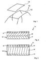
- Fig. 1
- eine Teilansicht eines Personenkraftwagens mit einem Dachmodul;
- Fig. 2
- einen Schnitt durch ein Dachmodul einer nicht beanspruchtes Teil der Erfindung;
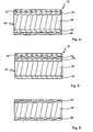
- Fig. 3
- einen Schnitt durch eine Ausführungsform eines Dachmoduls nach der Erfindung;
- Fig. 4
- einen Schnitt durch eine Ausführungsform eines Dachmoduls nach der Erfindung;
- Fig. 5
- einen Schnitt durch eine Ausführungsform eines Dachmoduls nach der Erfindung; und
- Fig. 6
- einen Schnitt durch einen Distanzhalter.
- Fig. 1
- a partial view of a passenger car with a roof module;
- Fig. 2
- a section through a roof module of an unclaimed part of the invention;
- Fig. 3
- a section through an embodiment of a roof module according to the invention;
- Fig. 4
- a section through an embodiment of a roof module according to the invention;
- Fig. 5
- a section through an embodiment of a roof module according to the invention; and
- Fig. 6
- a section through a spacer.
In
In
Die Außenhaut 16 ist an ihrer Unterseite bzw. Innenseite mit einem sogenannten Träger 18 hinterfüttert, der aus einer ersten Materiallage 20, die an die Außenhaut 16 grenzt, und einer zweiten Materiallage 22 besteht. Der Übergang zwischen der ersten Materiallage 20 und der zweiten Materiallage 22 ist unscharf, d.h. es liegt keine klar definierte Trennebene zwischen den beiden Materiallagen 20 und 22 vor. Vielmehr ist der Übergang zwischen den beiden Materiallagen als korrugierte bzw. im Querschnitt unregelmäßig gewellte Fläche ausgebildet.The
Die beiden Materiallagen 20 und 22 bestehen jeweils aus einem Polyurethanwerkstoff, wobei die erste Materiallage 20 einen Glasfaseranteil von 50 % und die zweite Materiallage 22 einen Glasfaseranteil zwischen 0 und 5 % aufweist. Dies führt zu einem Temperaturausdehnungskoeffizienten der ersten Materiallage 20 von 25 x 10-6 1/K und zu einem Temperaturausdehnungskoeffizienten der zweiten Materiallage 22 zwischen 40 x 10-6 1/K und 50 x 10-6 1/K. Der Temperaturausdehnungskoeffizient der Außenhaut 16 beträgt 75 x 10-6 1/K.The two
In
Der Träger 18 des Dachmoduls 24 umfaßt jedoch eine erste Materiallage 26, die an die Außenhaut 16 grenzt und durch einen Distanzhalter 28 von einer zweiten Materiallage 30 getrennt ist. Die erste Materiallage 26 besteht aus einem Polyurethanhartschaum mit einem Glasfaseranteil von 50 %, was zu einem Temperaturausdehnungskoeffizienten von 25 x 10-6 1/K führt. Die zweite Materiallage 30 besteht ebenfalls aus einem Polyurethanhartschaum, jedoch mit einem Glasfaseranteil zwischen 0 und 50 %. Der Temperaturausdehnungskoeffizient der zweiten Materiallage 30 hat beispielsweise einen Wert von 40 x 10-6 1/K.However, the
Der Distanzhalter, der mit einer Dicke zwischen 4 und 10 mm ausgebildet ist, besteht aus einer Kartonwabe, einer Kunststoffwabe oder auch aus einem Kunststoffschaum. Die erste Materiallage 26 und die zweite Materiallage 30 haben jeweils eine Dicke zwischen 0,5 und 1 mm.The spacer, which is formed with a thickness between 4 and 10 mm, consists of a cardboard honeycomb, a plastic honeycomb or a plastic foam. The
Bei dem in
Das Dachmodul 32 ist in symmetrischer Sandwich-Bauweise hergestellt, wobei die Gegenzugfolie 38 eine weitere Materiallage des Trägers 18 bildet.The
In
In
Die bei den vorstehend aufgeführten Ausführungsbeispielen ausgebildeten Materiallagen aus einem Glasfaser/Polyurethan-Gemisch können nach einem Spritzverfahren, beispielsweise nach einem sogenannten LFI(Long Fiber Injection)-Verfahren, oder gegebenenfalls auch nach einem Spritzverfahren, bei dem eine Wabenstruktur und/oder eine Glasmatte zum Einsatz kommen, aufgebracht sein.The material layers of a glass fiber / polyurethane mixture formed in the above-mentioned exemplary embodiments can be produced by a spraying process, for example by a so-called LFI (Long Fiber Injection) process or optionally also by a spraying process in which a honeycomb structure and / or a glass mat is used Use come, be upset.
- 1010
- Kraftfahrzeugmotor vehicle
- 1212
- Dachrahmenroof frame
- 1414
- Dachmodulroof module
- 1616
- Außenhautshell
- 1818
- Trägercarrier
- 2020
- erste Materiallagefirst material situation
- 2222
- zweite Materiallagesecond material situation
- 2424
- Dachmodulroof module
- 2626
- erste Materiallagefirst material situation
- 2828
- Distanzhalterspacer
- 3030
- zweite Materiallagesecond material situation
- 3232
- Dachmodulroof module
- 3434
- erste Materiallagefirst material situation
- 3636
- zweite Materiallagesecond material situation
- 3838
- GegenzugfolieGegenzugfolie
- 4040
- Dachmodulroof module
- 4242
- Materialschichtmaterial layer
- 4444
- Sperrschichtjunction
- 4646
- Sperrschichtjunction
Claims (14)
- Vehicle body part, comprising a material composite with an outer skin (16), which forms a surface which lies on the outside with respect to a passenger compartment of the vehicle, and has a first coefficient of thermal expansion, and a support (18), on which the outer skin (16) is arranged and with which a backing is provided for the latter, characterized in that the support (18) comprises at least a first material ply (26, 34, 42), facing the outer skin (16), and a second material ply (30, 36, 38), facing away from the outer skin (18), the coefficients of thermal expansion of which differ, so that no deformation of the material composite occurs when there is a change in temperature, the first material ply (26, 34, 42) and the second material ply (30, 36, 38) being separated from each other by a spacer (28) consisting of a cardboard honeycomb, a plastic honeycomb or a plastic foam.
- Vehicle body part according to Claim 1, characterized in that the coefficient of thermal expansion of the first material ply (26, 34) is less than the coefficient of thermal expansion of the second material ply (30, 36, 38) of the support (18).
- Vehicle body part according to Claim 1 or 2, characterized in that the coefficient of thermal expansion of the second material ply (30, 36, 38) is less than the coefficient of thermal expansion of the outer skin (16).
- Vehicle body part according to Claim 1 or 2, characterized in that the coefficient of thermal expansion of the second material ply (30, 36, 38) is greater than or equal to the coefficient of thermal expansion of the outer skin (16).
- Vehicle body part according to Claim 1, characterized in that the spacer (28) is arranged between layers (26, 30, 34, 36) of a polyurethane/glass-fibre mixture, which preferably form the first and second material plies.
- Vehicle body part according to Claim 1, characterized in that the spacer (28) is bounded on both sides by a barrier layer (44, 46), which preferably consists of a nonwoven material.
- Vehicle body part according to one of Claims 1 to 6, characterized in that the second material ply (30, 36) has a lower glass fibre content than the first material ply (26, 34).
- Vehicle body part according to one of Claims 1 to 7, characterized in that the support (18) comprises a backing foil (38) on its side facing away from the outer skin (16).
- Vehicle body part according to Claim 8, characterized in that the backing foil (38) consists of ABS.
- Vehicle body part according to one of Claims 1 to 9, characterized by a symmetrical sandwich structure.
- Vehicle body part according to one of Claims 1 to 10, characterized in that the support (18) comprises at least one material layer (42) which is adjacent to the outer skin (16) and limits the expansion of the outer skin (16).
- Vehicle body part according to Claim 11, characterized in that the material layer (42) is a glass fibre mat.
- Vehicle body part according to Claim 11, characterized in that the material layer (42) is an aluminium layer.
- Vehicle body part according to one of Claims 1 to 13, characterized in that it is a vehicle roof.
Applications Claiming Priority (2)
| Application Number | Priority Date | Filing Date | Title |
|---|---|---|---|
| DE2002121581 DE10221581B4 (en) | 2002-05-15 | 2002-05-15 | Vehicle body part |
| DE10221581 | 2002-05-15 |
Publications (3)
| Publication Number | Publication Date |
|---|---|
| EP1362771A2 EP1362771A2 (en) | 2003-11-19 |
| EP1362771A3 EP1362771A3 (en) | 2005-02-02 |
| EP1362771B1 true EP1362771B1 (en) | 2010-01-13 |
Family
ID=29265305
Family Applications (1)
| Application Number | Title | Priority Date | Filing Date |
|---|---|---|---|
| EP20030009954 Expired - Fee Related EP1362771B1 (en) | 2002-05-15 | 2003-04-30 | Composite car body part |
Country Status (2)
| Country | Link |
|---|---|
| EP (1) | EP1362771B1 (en) |
| DE (2) | DE10221581B4 (en) |
Families Citing this family (10)
| Publication number | Priority date | Publication date | Assignee | Title |
|---|---|---|---|---|
| DE10244287B4 (en) * | 2002-09-23 | 2013-07-11 | Basf Se | Spacer-containing, dellenfreie composite elements |
| DE10260525B4 (en) * | 2002-12-21 | 2016-10-20 | Volkswagen Ag | Method for producing a body component in sandwich construction |
| GB2408012B (en) * | 2003-11-13 | 2007-11-28 | Trysome Ltd | Composite article |
| DE102004019051A1 (en) * | 2004-04-20 | 2005-11-17 | Webasto Ag | Composite component for a vehicle body, in particular for a vehicle roof, and production method thereof |
| DE102005012796A1 (en) * | 2005-03-19 | 2006-09-21 | Hennecke Gmbh | Process for producing fiber-reinforced composite parts |
| DE102008030887A1 (en) | 2008-06-30 | 2010-01-07 | Webasto Ag | Motor vehicle i.e. cabriolet vehicle, has isolation layer provided with coating applied in tool according to In Mould Coating procedure, during manufacturing structure, and cover element provided with wear-protection layer |
| DE102009052038B4 (en) * | 2009-11-05 | 2013-10-10 | Webasto Ag | Flat composite component, in particular vehicle body part |
| DE102014014476B3 (en) * | 2014-09-25 | 2015-09-24 | Audi Ag | Stiffening element for a vehicle roof |
| CN108791517A (en) * | 2018-05-30 | 2018-11-13 | 富士房车(江苏)有限公司 | It is a kind of plate armour type fiberglass hyperbolic arch wheel enclose |
| DE102020103087A1 (en) | 2020-02-06 | 2021-08-12 | Georg Fritzmeier - GmbH & Co. KG | Process for the production of a body component and body component |
Family Cites Families (8)
| Publication number | Priority date | Publication date | Assignee | Title |
|---|---|---|---|---|
| DE7929367U1 (en) * | 1979-10-17 | 1981-02-26 | Bayerische Motoren Werke Ag, 8000 Muenchen | ROOF STRUCTURE FOR MOTOR VEHICLES, ESPECIALLY FOR A PERSONAL VEHICLE |
| CH671363A5 (en) * | 1986-11-21 | 1989-08-31 | Lonza Ag | |
| DE3908433A1 (en) * | 1988-03-17 | 1989-09-28 | Schmidt Gmbh R | Motor-vehicle roof and method for its production |
| SE512422C2 (en) * | 1997-09-17 | 2000-03-13 | Volvo Ab | Load-bearing vehicle roof and procedure for its manufacture |
| DE19949643C2 (en) * | 1999-10-14 | 2003-04-30 | Johnson Controls Headliner | Process for manufacturing roof reinforcement for vehicles and roof reinforcement |
| DE19955167C2 (en) * | 1999-11-16 | 2002-06-20 | Webasto Vehicle Sys Int Gmbh | Method for manufacturing a vehicle body part in a sandwich construction |
| DE10066339B4 (en) * | 2000-07-10 | 2010-09-16 | Webasto Ag | Vehicle roof part with a plastic outer skin, method and apparatus for producing the same |
| DE10202911C1 (en) * | 2002-01-25 | 2003-07-17 | Webasto Vehicle Sys Int Gmbh | Compound component for a vehicle roof has an outer skin, free of fibers, supported by a carrier structure with glass fiber reinforcement and a threshold layer between them with a raised fiber content |
-
2002
- 2002-05-15 DE DE2002121581 patent/DE10221581B4/en not_active Expired - Fee Related
-
2003
- 2003-04-30 EP EP20030009954 patent/EP1362771B1/en not_active Expired - Fee Related
- 2003-04-30 DE DE50312337T patent/DE50312337D1/en not_active Expired - Lifetime
Also Published As
| Publication number | Publication date |
|---|---|
| EP1362771A2 (en) | 2003-11-19 |
| EP1362771A3 (en) | 2005-02-02 |
| DE10221581A1 (en) | 2003-12-04 |
| DE50312337D1 (en) | 2010-03-04 |
| DE10221581B4 (en) | 2006-02-16 |
Similar Documents
| Publication | Publication Date | Title |
|---|---|---|
| DE102007007554B4 (en) | Method for producing a flat composite component of a vehicle | |
| DE10237090B4 (en) | Vehicle body part | |
| DE69926172T2 (en) | Impact energy absorbing structure for the upper portion of a vehicle body and energy absorbing member | |
| EP1362771B1 (en) | Composite car body part | |
| EP1640253A1 (en) | Composite part, particulary of a body of a vehicle, and process to make such a composite part | |
| EP1365942B1 (en) | Fastening element for part of a trim inside a motor vehicle | |
| EP1210226A1 (en) | Method for producing a sandwich panel and a body component | |
| DE102009017758A1 (en) | Roof lining element for use in motor vehicle i.e. passenger car, has channel arrangement integrated into element, where channel arrangement includes channel that is formed as recess in honeycomb core | |
| DE102009052038B4 (en) | Flat composite component, in particular vehicle body part | |
| DE10221582B4 (en) | Vehicle body part | |
| EP2243611B1 (en) | Method for manufacturing a vehicle body part | |
| DE102005029849A1 (en) | Method for manufacturing vehicle body structural element e.g. roof module, roof top cover, by inserting adjacent laminar parts of outer skin into sealing tool, while laminar parts are supported on carrier structure | |
| DE10221583B4 (en) | Vehicle body part | |
| DE102010020308A1 (en) | Method for manufacturing body component with layer construction, involves inserting profile structure in surface of core layer, where surface-structured core layer is formed in accordance with curve characteristic of body component | |
| WO1994007708A1 (en) | Head lining | |
| EP0248199B1 (en) | Multilayer lining element | |
| DE10202307B4 (en) | Plate-shaped component | |
| EP1498295B1 (en) | Tailgate for a motor vehicle | |
| DE10219495B4 (en) | Vehicle body part and method of making such part | |
| DE10241186B4 (en) | Roof module for a vehicle and manufacturing method therefor | |
| DE102017011761A1 (en) | Composite element, in particular for a vehicle | |
| EP3431280B1 (en) | Luggage structure for a commercial vehicle | |
| DE10224969B4 (en) | Roof module for a vehicle | |
| DE102017008097B4 (en) | Vehicle sandwich component and method for manufacturing a vehicle sandwich component | |
| EP1342650A1 (en) | Vehicle body part and method of producing such a part |
Legal Events
| Date | Code | Title | Description |
|---|---|---|---|
| PUAI | Public reference made under article 153(3) epc to a published international application that has entered the european phase |
Free format text: ORIGINAL CODE: 0009012 |
|
| AK | Designated contracting states |
Kind code of ref document: A2 Designated state(s): AT BE BG CH CY CZ DE DK EE ES FI FR GB GR HU IE IT LI LU MC NL PT RO SE SI SK TR |
|
| AX | Request for extension of the european patent |
Extension state: AL LT LV MK |
|
| PUAL | Search report despatched |
Free format text: ORIGINAL CODE: 0009013 |
|
| AK | Designated contracting states |
Kind code of ref document: A3 Designated state(s): AT BE BG CH CY CZ DE DK EE ES FI FR GB GR HU IE IT LI LU MC NL PT RO SE SI SK TR |
|
| AX | Request for extension of the european patent |
Extension state: AL LT LV MK |
|
| RIC1 | Information provided on ipc code assigned before grant |
Ipc: 7B 60R 13/02 B Ipc: 7B 62D 29/04 A Ipc: 7B 62D 25/06 B |
|
| RAP1 | Party data changed (applicant data changed or rights of an application transferred) |
Owner name: WEBASTO AG |
|
| 17P | Request for examination filed |
Effective date: 20050317 |
|
| AKX | Designation fees paid |
Designated state(s): DE FR GB NL |
|
| 17Q | First examination report despatched |
Effective date: 20061122 |
|
| GRAP | Despatch of communication of intention to grant a patent |
Free format text: ORIGINAL CODE: EPIDOSNIGR1 |
|
| GRAS | Grant fee paid |
Free format text: ORIGINAL CODE: EPIDOSNIGR3 |
|
| GRAA | (expected) grant |
Free format text: ORIGINAL CODE: 0009210 |
|
| AK | Designated contracting states |
Kind code of ref document: B1 Designated state(s): DE FR GB NL |
|
| REG | Reference to a national code |
Ref country code: GB Ref legal event code: FG4D Free format text: NOT ENGLISH |
|
| REF | Corresponds to: |
Ref document number: 50312337 Country of ref document: DE Date of ref document: 20100304 Kind code of ref document: P |
|
| REG | Reference to a national code |
Ref country code: NL Ref legal event code: T3 |
|
| PLBE | No opposition filed within time limit |
Free format text: ORIGINAL CODE: 0009261 |
|
| STAA | Information on the status of an ep patent application or granted ep patent |
Free format text: STATUS: NO OPPOSITION FILED WITHIN TIME LIMIT |
|
| 26N | No opposition filed |
Effective date: 20101014 |
|
| REG | Reference to a national code |
Ref country code: FR Ref legal event code: PLFP Year of fee payment: 14 |
|
| REG | Reference to a national code |
Ref country code: FR Ref legal event code: PLFP Year of fee payment: 15 |
|
| REG | Reference to a national code |
Ref country code: FR Ref legal event code: PLFP Year of fee payment: 16 |
|
| PGFP | Annual fee paid to national office [announced via postgrant information from national office to epo] |
Ref country code: DE Payment date: 20200423 Year of fee payment: 18 Ref country code: FR Payment date: 20200421 Year of fee payment: 18 Ref country code: NL Payment date: 20200420 Year of fee payment: 18 |
|
| PGFP | Annual fee paid to national office [announced via postgrant information from national office to epo] |
Ref country code: GB Payment date: 20200423 Year of fee payment: 18 |
|
| REG | Reference to a national code |
Ref country code: DE Ref legal event code: R119 Ref document number: 50312337 Country of ref document: DE |
|
| REG | Reference to a national code |
Ref country code: NL Ref legal event code: MM Effective date: 20210501 |
|
| GBPC | Gb: european patent ceased through non-payment of renewal fee |
Effective date: 20210430 |
|
| PG25 | Lapsed in a contracting state [announced via postgrant information from national office to epo] |
Ref country code: FR Free format text: LAPSE BECAUSE OF NON-PAYMENT OF DUE FEES Effective date: 20210430 Ref country code: GB Free format text: LAPSE BECAUSE OF NON-PAYMENT OF DUE FEES Effective date: 20210430 Ref country code: DE Free format text: LAPSE BECAUSE OF NON-PAYMENT OF DUE FEES Effective date: 20211103 |
|
| PG25 | Lapsed in a contracting state [announced via postgrant information from national office to epo] |
Ref country code: NL Free format text: LAPSE BECAUSE OF NON-PAYMENT OF DUE FEES Effective date: 20210501 |