EP1362718A2 - Bearing connector between a leaf spring end and an axle, particularly for a tandem axle of a truck - Google Patents
Bearing connector between a leaf spring end and an axle, particularly for a tandem axle of a truck Download PDFInfo
- Publication number
- EP1362718A2 EP1362718A2 EP03010002A EP03010002A EP1362718A2 EP 1362718 A2 EP1362718 A2 EP 1362718A2 EP 03010002 A EP03010002 A EP 03010002A EP 03010002 A EP03010002 A EP 03010002A EP 1362718 A2 EP1362718 A2 EP 1362718A2
- Authority
- EP
- European Patent Office
- Prior art keywords
- metal plate
- rubber body
- axle
- bearing connection
- connection according
- Prior art date
- Legal status (The legal status is an assumption and is not a legal conclusion. Google has not performed a legal analysis and makes no representation as to the accuracy of the status listed.)
- Granted
Links
Images

Classifications
-
- B—PERFORMING OPERATIONS; TRANSPORTING
- B60—VEHICLES IN GENERAL
- B60G—VEHICLE SUSPENSION ARRANGEMENTS
- B60G11/00—Resilient suspensions characterised by arrangement, location or kind of springs
- B60G11/32—Resilient suspensions characterised by arrangement, location or kind of springs having springs of different kinds
- B60G11/34—Resilient suspensions characterised by arrangement, location or kind of springs having springs of different kinds including leaf springs
- B60G11/38—Resilient suspensions characterised by arrangement, location or kind of springs having springs of different kinds including leaf springs and also rubber springs
- B60G11/40—Resilient suspensions characterised by arrangement, location or kind of springs having springs of different kinds including leaf springs and also rubber springs the rubber springs being attached to the axle
-
- B—PERFORMING OPERATIONS; TRANSPORTING
- B60—VEHICLES IN GENERAL
- B60G—VEHICLE SUSPENSION ARRANGEMENTS
- B60G11/00—Resilient suspensions characterised by arrangement, location or kind of springs
- B60G11/02—Resilient suspensions characterised by arrangement, location or kind of springs having leaf springs only
- B60G11/10—Resilient suspensions characterised by arrangement, location or kind of springs having leaf springs only characterised by means specially adapted for attaching the spring to axle or sprung part of the vehicle
-
- B—PERFORMING OPERATIONS; TRANSPORTING
- B60—VEHICLES IN GENERAL
- B60G—VEHICLE SUSPENSION ARRANGEMENTS
- B60G2202/00—Indexing codes relating to the type of spring, damper or actuator
- B60G2202/10—Type of spring
- B60G2202/11—Leaf spring
-
- B—PERFORMING OPERATIONS; TRANSPORTING
- B60—VEHICLES IN GENERAL
- B60G—VEHICLE SUSPENSION ARRANGEMENTS
- B60G2202/00—Indexing codes relating to the type of spring, damper or actuator
- B60G2202/10—Type of spring
- B60G2202/14—Plastic spring, e.g. rubber
-
- B—PERFORMING OPERATIONS; TRANSPORTING
- B60—VEHICLES IN GENERAL
- B60G—VEHICLE SUSPENSION ARRANGEMENTS
- B60G2204/00—Indexing codes related to suspensions per se or to auxiliary parts
- B60G2204/10—Mounting of suspension elements
- B60G2204/12—Mounting of springs or dampers
- B60G2204/125—Mounting of rubber type springs
Definitions
- the invention relates to a bearing connection between a leaf spring end and an axle bearing, in particular a double-axle unit of a truck according to the preamble of claim 1.
- a known bearing connection between a leaf spring end and one Axle bearing of a double unit of a truck includes a spring saddle, which consists of a stable lower metal plate and a stable upper metal plate with a vulcanized in between Rubber body and one vulcanized on the upper metal plate upper rubber layer.
- the lower metal plate is at the top arranged and fastened the axle bearing.
- On the on the top metal plate vulcanized upper rubber layer is the leaf spring end with his Bottom on.
- the rubber body is cuboid here and can be vulcanized Intermediate sheets can be divided into layers.
- the metal plates, especially on the adhesive surface for the rubber body and possibly the Intermediate sheets shaped in a circular arc or approximately circular arc be that the associated center of the circle in a rotating pole of the relative movement lies between the axis and the leaf spring.
- the cuboid shape of the rubber body means there are no additional measures at maximum loads there is a risk that the rubber body buckles and thus the spring saddle is damaged and destroyed. Therefore are here in the direction of travel and possibly transverse to the direction of travel in the horizontal direction as well also provided stops acting in the vertical direction, which by laterally protruding projections of the upper and lower metal plate are formed are. These attacks lead to complex designs of the Metal plates. In addition, the extreme position takes place in the active position Attacks an unfavorable metal-to-metal investment connection with relative high noise level and fast wear.
- the object of the invention is a generic bearing connection between a leaf spring end and an axle bearing with regard to the spring saddle to further develop that the attacks according to the prior art can be dispensed with are.
- the rubber body has a trapezoidal shape when viewed in the axial direction Form and seen in the vehicle longitudinal direction essentially rectangular shape. With horizontal deformations taking place under load this trapezoidal formation of the rubber body offers an optimal Support so that there is no buckling of the spring saddle or the rubber body can take place and therefore not the attacks described above required are. This makes the construction of the spring saddle easier overall and less expensive with further advantages in terms of reduced noise and reduced wear at maximum loads.
- the Rubber body symmetrical, the trapezoidal shape isosceles is carried out with an angle of attack in a range of about 65 ° to 75 °, preferably 70 °.
- the rubber body should be seen in the vehicle's longitudinal direction deviate slightly from a rectangular shape and with a trapezoidal shape form an angle of attack of about 85 ° to 89 °, preferably 87 °.
- leaf spring ends In order to are in the usual circumstances and loads, such as in connection with double-axle units on trucks there are optimal supports achieved by leaf spring ends.
- the upper metal plate protrudes with the vulcanized rubber layer on both sides in the vehicle's longitudinal direction with metal plate end areas, these down are slightly kinked. Due to this kink, the relatively thick upper Metal plate with the relatively thick, vulcanized rubber layer of the bending line follow a spring-loaded leaf spring. The one on the top metal plate Vulcanized, relatively thick rubber layer transfers the pressure of the leaf spring ends on the upper metal plate, which in turn optimized an Distribution of tension in the rubber body with its trapezoidal shape.
- the upper, relatively thick rubber layer also serves to decouple small ones Vibrations and noises between leaf spring and axle. Also find no relative movements between the leaf spring end and this rubber layer instead, since movements in all three spatial directions are molecular in the Rubber layer are added, so that advantageously no friction here and so there is no abrasion and no wear. For molecular imaging Minor movements in this rubber layer is in its rubber layer height to be dimensioned accordingly thick.
- the rubber layer shapes approach in Axis direction seen a radius contour, so that one around a rotating pole caused circular movement through the intermediate plates and metal plates limited rubber layers in the edge area are relieved in comparison compared to intermediate plates or flat rubber layers.
- there are three Intermediate plates are provided, which are arranged in the rubber body that four horizontal layers are formed, which are in thickness from top to bottom increase.
- an upward-facing recess may be contained in the rubber body taken with its lower area and vulcanized with the underside is. Strong material thicknesses are on the lower metal plate for fastenings especially in the edge and corner areas surrounding the rubber body required.
- the lower metal plate made in two parts with a top plate part and bottom plate part be, wherein the rubber body is vulcanized onto the top plate part.
- the Subplate part contains an upward-facing recess into which the Upper plate is inserted and screwed to the lower plate part.
- the lower metal plate as Forged part to be rectangular, being the lower surface of the rubber body overhanged on all sides with an overhang.
- the four corners of the Metal plate especially in the area of the edge overhang, can face down pointing projections in which threaded holes from below are attached for screwing in fastening screws.
- axle bearing is designed in the manner of a clamp where the lower metal plate of the spring saddle forms the upper bracket part, which with clamping screws screwed into the threaded holes braced against a lower longitudinal member supporting the axle from below is.
- the lower metal plate has a dual function as part the spring saddle on which the rubber body is vulcanized and also as a clamp part for an axle bracket.
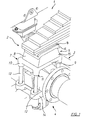
- Figure 1 is a bearing connection 1 between a multi-layer leaf spring end 2 and an axle bearing 3 of a double-axle unit 4 of a truck shown.
- the bearing connection 1 consists of a spring saddle 5, which an upper metal plate 6 and a lower metal plate 7 includes one vulcanized rubber body in between 8. On the upper metal plate also vulcanized an upper rubber layer 8.
- the lower metal plate 7 is designed as a forged part rectangular and towered over the lower surface of the rubber body 8 on all sides with an edge projection 9. In the four corners of the lower metal plate 7 are downward extensions 10 integrally formed, in which threaded holes 11 are attached from below are.
- the axle bearing for the axle area 12 is designed in the manner of a clamp, in which the lower metal plate 7 of the spring saddle 5, the upper bracket part forms, which is screwed into the threaded bores 11 Tensioning screws 13 against a supporting the axis area 12 from below Longitudinal lower member 14 is clamped in the manner of a bearing block.
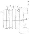
- the Rubber body 15 isosceles trapezoidal shape with an angle of attack 16 of approx. 70 °.
- the rubber body 15 In the rubber body 15 are approximately three intermediate sheets 17 vulcanized, the rubber body 15 in four approximately the same divide strong rubber horizontal layers 18, which, however, from the top increase in thickness below.
- the intermediate plates are flat and are also with end regions 19 in the direction of travel over the rubber body 15 in front.
- the upper, relatively thick metal plate 6 with the vulcanized also relatively thick Rubber layer 8 projects above the upper area of rubber body 15 with metal plate end areas 19 on both sides, these slightly bent downwards are and thus a bend line of the leaf spring end when compressed follow leaf spring.
- Rubber layer 8 projects above the upper area of rubber body 15 with metal plate end areas 19 on both sides, these slightly bent downwards are and thus a bend line of the leaf spring end when compressed follow leaf spring.
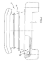
- Fig. 3 is a side view of the spring saddle 5 in the vehicle longitudinal direction seen with the lower metal plate 7 the rubber body 15 of the upper metal plate 6 and the upper rubber layer 8.
- the rubber body 15 is in this view almost rectangular with a slight trapezoidal shape with an angle of attack 21 of approx. 87 °.
- the intermediate plate end areas 22 also protrude laterally from the rubber body 15 in this view.
- the central longitudinal plane 23 can be covered due to special installation conditions on the lower metal plate 7, as shown opposite the central longitudinal plane of the rubber body 15 are offset.
- Fig. 4 is a side view seen in the axial direction of a slightly modified Embodiment of a spring saddle 5 shown, in all essentials Features constructed according to the spring saddle from Figures 2 and 3 is.
- the lower metal plate 7 has an upwardly facing recess 24 as in a partial section shown.
- this recess is the lower area or the lowest rubber horizontal layer 18 of the rubber body 15 added, so that hereby a height reduction of the spring saddle 5 is possible.
- the recess 24 surrounds the lower region of the rubber body 15 with an edge as a free space, so that the rubber body 15 laterally according to its load can move freely.
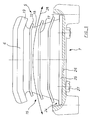
- FIG. 5 Another modified embodiment of a spring saddle 5 is in the corresponding Side view shown in Fig. 5.
- the rubber body is there too 15 with its lower area in a recess 24 for a total height reduction added.
- the lower metal plate 7 is here, however executed in two parts and consists of a top plate part 25 and one Lower plate part 26.
- the rubber body 15 is vulcanized onto the upper plate part 25.
- the top plate part 25 is placed on the bottom plate part 26 and screwed by means of screws 27.
- the metal plate end regions also protrude in the embodiment according to FIG. 5 19 of the upper metal plate 6 on both sides of the rubber body 15 and are there slightly bent downwards.
- the intermediate plate end areas are also corresponding here 22 of the intermediate plates 17 slightly bent downwards, so that the shape of the rubber horizontal layers 18 an arc 28 are approximated with a radius in a rotating pole.
Abstract
Description
Die Erfindung betrifft eine Lagerverbindung zwischen einem Blattfederende
und einem Achslager, insbesondere eines Doppelachsaggregats eines Lastkraftwagens
nach dem Oberbegriff des Anspruchs 1.The invention relates to a bearing connection between a leaf spring end
and an axle bearing, in particular a double-axle unit of a truck
according to the preamble of
Eine bekannte Lagerverbindung zwischen einem Blattfederende und einem
Achslager eines Doppelaggregats eines Lastkraftwagens (EP 1 002 674 A2)
umfasst einen Federsattel, der aus einer stabilen unteren Metallplatte und einer
stabilen oberen Metallplatte mit einem dazwischen festhaftend einvulkanisierten
Gummikörper und einer auf der oberen Metallplatte aufvulkanisierten
oberen Gummischicht besteht. Dabei ist die untere Metallplatte am oberen Bereich
des Achslagers angeordnet und befestigt. Auf der an der oberen Metallplatte
aufvulkanisierten oberen Gummischicht liegt das Blattfederende mit seiner
Unterseite auf.A known bearing connection between a leaf spring end and one
Axle bearing of a double unit of a truck (
Der Gummikörper ist hier quaderförmig ausgebildet und kann durch einvulkanisierte Zwischenbleche schichtförmig unterteilt sein. Zudem können die Metallplatten, insbesondere an der Haftfläche für den Gummikörper sowie ggf. die Zwischenbleche kreisbogenförmig oder annähernd kreisbogenförmig so geformt sein, dass der zugehörige Kreismittelpunkt in einem Drehpol der Relativbewegung zwischen Achse und Blattfeder liegt. The rubber body is cuboid here and can be vulcanized Intermediate sheets can be divided into layers. In addition, the metal plates, especially on the adhesive surface for the rubber body and possibly the Intermediate sheets shaped in a circular arc or approximately circular arc be that the associated center of the circle in a rotating pole of the relative movement lies between the axis and the leaf spring.
Durch die hier quaderförmige Gestalt des Gummikörpers besteht ohne Zusatzmaßnahmen bei Höchstbelastungen die Gefahr, dass der Gummikörper ausknickt und somit der Federsattel beschädigt und zerstört wird. Daher sind hier in Fahrtrichtung und ggf. quer zur Fahrtrichtung in Horizontalrichtung sowie auch in Vertikalrichtung wirkende Anschläge vorgesehen, welche durch sich seitlich überragende Fortsätze der oberen und unteren Metallplatte gebildet sind. Diese Anschläge führen zu konstruktiv aufwendigen Gestaltungen der Metallplatten. Zudem erfolgt bei Extrembelastungen in der Wirkstellung der Anschläge eine ungünstige Anlageverbindung von Metall zu Metall mit relativ hoher Geräuschentwicklung und schnellem Verschleiß.The cuboid shape of the rubber body means there are no additional measures at maximum loads there is a risk that the rubber body buckles and thus the spring saddle is damaged and destroyed. Therefore are here in the direction of travel and possibly transverse to the direction of travel in the horizontal direction as well also provided stops acting in the vertical direction, which by laterally protruding projections of the upper and lower metal plate are formed are. These attacks lead to complex designs of the Metal plates. In addition, the extreme position takes place in the active position Attacks an unfavorable metal-to-metal investment connection with relative high noise level and fast wear.
Aufgabe der Erfindung ist es eine gattungsgemäße Lagerverbindung zwischen einem Blattfederende und einem Achslager hinsichtlich des Federsattels so weiterzubilden, dass die Anschläge nach dem Stand der Technik entbehrlich sind.The object of the invention is a generic bearing connection between a leaf spring end and an axle bearing with regard to the spring saddle to further develop that the attacks according to the prior art can be dispensed with are.
Diese Aufgabe wird mit den Merkmalen des Anspruchs 1 gelöst.This object is achieved with the features of
Gemäß Anspruch 1 weist der Gummikörper in Achsrichtung gesehen eine trapezförmige
Form und in Fahrzeuglängsrichtung gesehen eine im wesentlichen
rechteckige Form auf. Bei unter Last stattfindenden, horizontalen Verformungen
bietet diese trapezförmige Ausbildung des Gummikörpers eine optimale
Abstützung, so dass kein Ausknicken des Federsattels bzw. des Gummikörpers
stattfinden kann und damit die eingangs geschilderten Anschläge nicht
erforderlich sind. Damit wird der Aufbau des Federsattels insgesamt einfacher
und kostengünstiger mit weiteren Vorteilen hinsichtlich einer reduzierten Geräuschentwicklung
und eines reduzierten Verschleißes bei Höchstbelastungen.According to
In einer besonders bevorzugten Ausführungsform nach Anspruch 2 ist der
Gummikörper symmetrisch ausgebildet, wobei die Trapezform gleichschenkelig
ausgeführt ist mit einem Anstellwinkel in einem Bereich von etwa 65° bis
75°, vorzugsweise 70°. Der Gummikörper soll in Fahrzeuglängsrichtung gesehen
von einer Rechteckform geringfügig abweichen und eine Trapezform mit
einem Anstellwinkel von etwa 85° bis 89°, vorzugsweise 87° bilden. Damit
werden bei üblichen Gegebenheiten und Belastungen, wie sie in Verbindung
mit Doppelachsaggregaten an Lastkraftwagen auftreten optimale Abstützungen
von Blattfederenden erzielt.In a particularly preferred embodiment according to
In einer Weiterbildung nach Anspruch 3 überragt die obere Metallplatte mit der
oberen aufvulkanisierten Gummischicht den Gummikörper beidseitig in Fahrzeuglängsrichtung
mit Metallplattenendbereichen, wobei diese nach unten
leicht abgeknickt sind. Durch diese Abknickung kann die relativ dicke obere
Metallplatte mit der relativ dicken, aufvulkanisierten Gummischicht der Biegelinie
einer eingefederten, aufliegenden Blattfeder folgen. Die auf die obere Metallplatte
aufvulkanisierte relativ dicke Gummischicht überträgt den Druck von
den Blattfederenden auf die obere Metallplatte, die wiederum eine optimierte
Spannungsverteilung in den Gummikörper mit seiner Trapezform weiterleitet.In a further development according to
Die obere relativ dicke Gummischicht dient weiter zur Entkopplung von kleinen Schwingungen und Geräuschen zwischen Blattfeder und Achse. Zudem finden zwischen dem Blattfederende und dieser Gummischicht keine Relativbewegungen statt, da Bewegungen in allen drei Raumrichtungen molekular in der Gummischicht aufgenommen werden, so dass vorteilhaft hier keine Reibung und damit kein Abrieb und kein Verschleiß entsteht. Für die molekulare Aufnahme kleinerer Bewegungen in dieser Gummischicht ist diese in ihrer Gummischichthöhe entsprechend dick zu dimensionieren.The upper, relatively thick rubber layer also serves to decouple small ones Vibrations and noises between leaf spring and axle. Also find no relative movements between the leaf spring end and this rubber layer instead, since movements in all three spatial directions are molecular in the Rubber layer are added, so that advantageously no friction here and so there is no abrasion and no wear. For molecular imaging Minor movements in this rubber layer is in its rubber layer height to be dimensioned accordingly thick.
Eine weitere Verbesserung hinsichtlich des Abstützverhaltens und gleichmäßiger
Belastungsverteilungen im Gummikörper ergibt sich nach Anspruch 4 dadurch,
dass im Gummikörper wenigstens ein im Vergleich zu der unteren und
oberen Metallplatte dünneres Zwischenblech einvulkanisiert ist welches in
Fahrtrichtung beidseitig mit Zwischenblechendbereichen aus dem Gummikörper
vorsteht. Eine weitere Verbesserung ergibt sich zudem mit den Merkmalen
des Anspruchs 5, wobei die teilweise noch im Gummikörper enthaltenen Zwischenblechendbereiche
entsprechend den Metallplattenendbereichen der oberen
und ggf. der unteren Metallplatte nach unten leicht abgeknickt sind. Damit
folgen auch die Zwischenbleche etwa der Form der Biegelinie einer eingefederten
Blattfeder. Mit anderen Worten nähern sich die Gummischichtformen in
Achsrichtung gesehen einer Radius-Kontur, so dass bei einer um einen Drehpol
veranlassten Kreisbewegung die durch die Zwischenbleche und Metallplatten
begrenzten Gummischichten im Randbereich entlastet werden im Vergleich
gegenüber eben ausgeführten Zwischenblechen bzw. ebenen Gummischichten.
In einer bevorzugten Ausführungsform nach Anspruch 6 sind drei
Zwischenbleche vorgesehen, die so im Gummikörper angeordnet sind, dass
vier Horizontalschichten gebildet sind, welche in der Dicke von oben nach unten
zunehmen.Another improvement in support behavior and more even
Load distributions in the rubber body result according to claim 4
that in the rubber body at least one compared to the bottom and
vulcanized upper metal plate which is in
Direction of travel on both sides with intermediate plate end areas from the rubber body
protrudes. A further improvement also results from the features
of
Wenn der Bauraum im Bereich der Achslagerung begrenzt ist kann zur Verringerung
der Gesamt-Bauhöhe gemäß Anspruch 7 in der unteren Metallplatte
eine nach oben weisende Ausnehmung enthalten sein, in der der Gummikörper
mit seinem unteren Bereich aufgenommen und mit der Unterseite anvulkanisiert
ist. Starke Materialstärken sind an der unteren Metallplatte für Befestigungen
insbesondere in den Gummikörper umgebenden Rand- und Eckbereichen
erforderlich.If the installation space in the area of the axle bearing is limited, it can be reduced
the overall height according to
In einer weiteren Ausführungsvariante nach Anspruch 8 kann die untere Metallplatte
zweiteilig mit einem Oberplattenteil und Unterplattenteil ausgeführt
sein, wobei auf das Oberplattenteil der Gummikörper aufvulkanisiert ist. Das
Unterplattenteil enthält eine nach oben weisende Ausnehmung, in die die
Oberplatte eingesetzt und mit dem Unterplattenteil verschraubt ist. Dadurch
können sich herstellungstechnische und montagetechnische Freiräume ergeben,
die je nach den speziellen Einbaumöglichkeiten nutzbar sind. Insbesondere
kann auch hier eine Ausführung mit relativ geringer Gesamtbauhöhe erstellt
werden.In a further embodiment variant according to
Für eine Befestigung der unteren Metallplatte und damit des Federsattels kann in an sich bekannter Weise nach Anspruch 9 die untere Metallplatte als Schmiedeteil rechteckig ausgeführt sein, wobei sie die Unterfläche des Gummikörpers allseitig mit einem Randüberstand überragt. In den vier Ecken der Metallplatte, insbesondere im Bereich des Randüberstands können nach unten weisende Fortsätze angeformt sein, in denen von unten her Gewindebohrungen zum Einschrauben von Befestigungsschrauben angebracht sind.Can be used to attach the lower metal plate and thus the spring saddle in a conventional manner according to claim 9, the lower metal plate as Forged part to be rectangular, being the lower surface of the rubber body overhanged on all sides with an overhang. In the four corners of the Metal plate, especially in the area of the edge overhang, can face down pointing projections in which threaded holes from below are attached for screwing in fastening screws.
Eine besonders bevorzugte Anordnung und Montage ergibt sich dann nach
Anspruch 10, wenn das Achslager in der Art einer Spannklammer ausgebildet
ist, bei der die untere Metallplatte des Federsattels das obere Klammerteil bildet,
welches mit in die Gewindebohrungen eingeschraubten Spannschrauben
gegen ein die Achse von unten her abstützendes Längsträgerunterteil verspannt
ist. Die untere Metallplatte hat somit hier eine Doppelfunktion als Teil
des Federsattels auf welchem der Gummikörper aufvulkanisiert ist und
zugleich als Spannklammerteil für eine Achshalterung.A particularly preferred arrangement and assembly then follows
Anhand einer Zeichnung wird die Erfindung näher erläutert.The invention is explained in more detail with reference to a drawing.
Es zeigen:
- Fig.1
- eine perspektivische Ansicht einer Lagerverbindung zwischen einem Blattfederende und einem Achslager eines Doppelaggregats eines Lastkraftwagens,
- Fig.2
- eine Seitenansicht eines Federsattels als Drucklager in Achsrichtung gesehen,
- Fig.3
- den Federsattel nach
Figur 2 in Fahrzeuglängsrichtung gesehen, - Fig.4
- eine alternative Ausführungsform eines Federsattels und
- Fig.5
- eine weitere alternative Ausführungsform eines Federsattels.
- Fig.1
- 1 shows a perspective view of a bearing connection between a leaf spring end and an axle bearing of a double unit of a truck,
- Fig.2
- a side view of a spring saddle seen as a thrust bearing in the axial direction,
- Figure 3
- seen the spring caliper according to Figure 2 in the vehicle longitudinal direction,
- Figure 4
- an alternative embodiment of a spring saddle and
- Figure 5
- another alternative embodiment of a spring saddle.
In Fig.1 ist eine Lagerverbindung 1 zwischen einem mehrlagigen Blattfederende
2 und einem Achslager 3 eines Doppelachsaggregats 4 eines Lastkraftwagens
gezeigt. Die Lagerverbindung 1 besteht aus einem Federsattel 5, welcher
eine obere Metallplatte 6 und eine untere Metallplatte 7 umfasst mit einem
dazwischen einvulkanisierten Gummikörper 8. Auf der oberen Metallplatte ist
zudem eine obere Gummischicht 8 aufvulkanisiert.In Figure 1 is a
Die untere Metallplatte 7 ist als Schmiedeteil rechteckig ausgeführt und überragt
die Unterfläche des Gummikörpers 8 allseitig mit einem Randüberstand 9.
In den vier Ecken der unteren Metallplatte 7 sind nach unten weisende Fortsätze
10 angeformt, in denen von unten her Gewindebohrungen 11 angebracht
sind.The
Das Achslager für den Achsbereich 12 ist in der Art einer Spannklammer ausgebildet,
bei der die untere Metallplatte 7 des Federsattels 5 das obere Klammerteil
bildet, welches mit in die Gewindebohrungen 11 eingeschraubten
Spannschrauben 13 gegen ein den Achsbereich 12 von unten her abstützendes
Längsträgerunterteil 14 in der Art eines Lagerbocks verspannt ist.The axle bearing for the
In Fig. 2 ist eine Seitenansicht des Federsattels 5 in Achsrichtung gesehen
dargestellt mit der oberen Metallplatte 6 mit aufvulkanisierter oberer Gummischicht
8 und der unteren Metallplatte 7 mit den angeformten Fortsätzen 10
und dem dazwischen eingeformten Gummikörper 15. In dieser Ansicht hat der
Gummikörper 15 eine gleichschenkelige Trapezform mit einem Anstellwinkel
16 von ca. 70°. Im Gummikörper 15 sind etwa horizontal verlaufende drei Zwischenbleche
17 einvulkanisiert, die den Gummikörper 15 in vier etwa gleich
starke Gummihorizontalschichten 18 unterteilen, welche jedoch von oben nach
unten in ihrer Dicke etwas zunehmen. Die Zwischenbleche sind hier eben und
stehen zudem mit Endbereichen 19 in Fahrtrichtung über den Gummikörper 15
vor.2 shows a side view of the
Die obere, relativ dicke Metallplatte 6 mit der ebenfalls relativ dicken aufvulkanisierten
Gummischicht 8 überragt den oberen Bereich des Gummikörpers 15
beidseitig mit Metallplattenendbereichen 19, wobei diese nach unten leicht abgeknickt
sind und somit einer Biegelinie des Blattfederendes bei eingefederter
Blattfeder folgen. Um hier Belastungsspitzen im Gummikörper 15 zu vermeiden
ist der Übergang zu den Metallplattenendbereichen 19 in einer Bogenform
20 ausgeführt.The upper, relatively
In Fig. 3 ist eine Seitenansicht des Federsattels 5 in Fahrzeuglängsrichtung
gesehen dargestellt mit der unteren Metallplatte 7 dem Gummikörper 15 der
oberen Metallplatte 6 und der oberen Gummischicht 8. Der Gummikörper 15 ist
in dieser Ansicht nahezu rechteckig ausgebildet mit einer geringförmigen Trapezform
mit einem Anstellwinkel 21 von ca. 87°. Die Zwischenblechendbereiche
22 stehen auch in dieser Ansicht seitlich aus dem Gummikörper 15 vor.
Aufgrund spezieller Einbaugegebenheiten kann die Mittellängsebene 23 bezogen
auf die untere Metallplatte 7, wie dargestellt gegenüber der Mittellängsebene
des Gummikörpers 15 versetzt liegen.In Fig. 3 is a side view of the
In Fig. 4 ist eine in Achsrichtung gesehene Seitenansicht einer etwas modifizierten
Ausführungsform eines Federsattels 5 dargestellt, der in allen wesentlichen
Merkmalen entsprechend dem Federsattel aus den Figuren 2 und 3 aufgebaut
ist. Der Unterschied besteht darin, dass hier die untere Metallplatte 7
eine nach oben weisende Ausnehmung 24 aufweist wie in einem Teilschnitt
gezeigt. In dieser Ausnehmung ist der untere Bereich bzw. die unterste Gummihorizontalschicht
18 des Gummikörpers 15 aufgenommen, so dass hiermit
eine Bauhöhenreduzierung des Federsattels 5 möglich ist. Die Ausnehmung
24 umgibt den unteren Bereich des Gummikörpers 15 mit einem Rand als Freiraum,
so dass sich der Gummikörper 15 entsprechend seiner Belastung seitlich
frei bewegen kann.In Fig. 4 is a side view seen in the axial direction of a slightly modified
Embodiment of a
Eine weitere modifizierte Ausführungsform eines Federsattels 5 ist in der entsprechenden
Seitenansicht in Fig. 5 dargestellt. Auch dort ist der Gummikörper
15 mit seinem unteren Bereich in einer Ausnehmung 24 für eine Gesamthöhenreduzierung
aufgenommen. Die untere Metallplatte 7 ist hier jedoch
zweiteilig ausgeführt und besteht aus einem Oberplattenteil 25 und aus einem
Unterplattenteil 26. Auf dem Oberplattenteil 25 ist der Gummikörper 15 aufvulkanisiert.
Das Oberplattenteil 25 ist auf das Unterplattenteil 26 aufgesetzt und
mittels Schrauben 27 verschraubt.Another modified embodiment of a
Auch in der Ausführungsform nach Fig. 5 überragen die Metallplattenendbereiche
19 der oberen Metallplatte 6 beidseitig den Gummikörper 15 und sind dort
leicht nach unten abgeknickt. Zudem sind auch hier entsprechend die Zwischenblechendbereiche
22 der Zwischenbleche 17 nach unten leicht abgeknickt,
so dass die Form der Gummihorizontalschichten 18 einem Kreisbogen
28 mit einem Radius in einem Drehpol angenähert sind.The metal plate end regions also protrude in the embodiment according to FIG. 5
19 of the
Claims (10)
auf der oberen Gummischicht (8) das Blattfederende (2) mit seiner Unterseite aufliegt,
the leaf spring end (2) rests with its underside on the upper rubber layer (8),
dass das Unterplattenteil (26) eine nach oben weisende Ausnehmung enthält, in die das Oberplattenteil (25) eingesetzt und mit dem Unterplattenteil (26) verschraubt ist.Bearing connection according to one of claims 1 to 6, characterized in that the lower metal plate (7) is made in two parts with an upper plate part (25) and lower plate part (26) by vulcanizing the rubber body (15) onto the upper plate part, and
that the lower plate part (26) contains an upwardly facing recess into which the upper plate part (25) is inserted and screwed to the lower plate part (26).
dass in den vier Ecken der unteren Metallplatte (7) nach unten weisende Fortsätze (10) angeformt sind, in denen von unten her Gewindebohrungen (11) angebracht sind.Bearing connection according to one of claims 1 to 8, characterized in that the lower metal plate (7) is designed as a forged part rectangular and the bottom surface of the rubber body (15) projects on all sides with an edge projection (9),
that in the four corners of the lower metal plate (7) downward extensions (10) are formed, in which threaded holes (11) are made from below.
Applications Claiming Priority (2)
| Application Number | Priority Date | Filing Date | Title |
|---|---|---|---|
| DE20207770U | 2002-05-17 | ||
| DE20207770U DE20207770U1 (en) | 2002-05-17 | 2002-05-17 | Bearing connection between a leaf spring end and an axle guide, in particular a double-axle unit of a truck |
Publications (3)
| Publication Number | Publication Date |
|---|---|
| EP1362718A2 true EP1362718A2 (en) | 2003-11-19 |
| EP1362718A3 EP1362718A3 (en) | 2005-03-23 |
| EP1362718B1 EP1362718B1 (en) | 2006-04-05 |
Family
ID=7971269
Family Applications (1)
| Application Number | Title | Priority Date | Filing Date |
|---|---|---|---|
| EP03010002A Expired - Lifetime EP1362718B1 (en) | 2002-05-17 | 2003-05-02 | Bearing connector between a leaf spring end and an axle, particularly for a tandem axle of a truck |
Country Status (4)
| Country | Link |
|---|---|
| EP (1) | EP1362718B1 (en) |
| AT (1) | ATE322392T1 (en) |
| DE (2) | DE20207770U1 (en) |
| ES (1) | ES2261816T3 (en) |
Cited By (2)
| Publication number | Priority date | Publication date | Assignee | Title |
|---|---|---|---|---|
| WO2007004949A1 (en) * | 2005-06-30 | 2007-01-11 | Volvo Lastvagnar Ab | Rubber spring for a vehicle wheel axle suspension |
| US8540262B2 (en) | 2010-02-25 | 2013-09-24 | Man Truck & Bus Ag | Commercial vehicle and device for attaching a spring element to a commercial vehicle axle |
Citations (1)
| Publication number | Priority date | Publication date | Assignee | Title |
|---|---|---|---|---|
| EP1002674A2 (en) | 1998-11-20 | 2000-05-24 | MAN Nutzfahrzeuge Aktiengesellschaft | Joint between the ends of a leaf spring and axle supports of a commercial vehicle tandem axle unit |
Family Cites Families (5)
| Publication number | Priority date | Publication date | Assignee | Title |
|---|---|---|---|---|
| DE943932C (en) * | 1952-10-02 | 1956-06-01 | Opel Adam Ag | Storage of semi-elliptical springs on motor vehicles |
| DE69310779T2 (en) * | 1992-02-01 | 1997-12-18 | Mitsubishi Motors Corp | Rear wheel steering device |
| DE4221996C2 (en) * | 1992-07-04 | 1996-09-12 | Man Nutzfahrzeuge Ag | Double axle unit for trucks |
| JPH10138726A (en) * | 1996-11-12 | 1998-05-26 | Hino Motors Ltd | Rear axle suspension for two rear axle vehicle |
| US6206407B1 (en) * | 1998-12-18 | 2001-03-27 | Freightliner Llc | Vehicle suspension system |
-
2002
- 2002-05-17 DE DE20207770U patent/DE20207770U1/en not_active Expired - Lifetime
-
2003
- 2003-05-02 EP EP03010002A patent/EP1362718B1/en not_active Expired - Lifetime
- 2003-05-02 ES ES03010002T patent/ES2261816T3/en not_active Expired - Lifetime
- 2003-05-02 DE DE50302861T patent/DE50302861D1/en not_active Expired - Fee Related
- 2003-05-02 AT AT03010002T patent/ATE322392T1/en not_active IP Right Cessation
Patent Citations (1)
| Publication number | Priority date | Publication date | Assignee | Title |
|---|---|---|---|---|
| EP1002674A2 (en) | 1998-11-20 | 2000-05-24 | MAN Nutzfahrzeuge Aktiengesellschaft | Joint between the ends of a leaf spring and axle supports of a commercial vehicle tandem axle unit |
Cited By (2)
| Publication number | Priority date | Publication date | Assignee | Title |
|---|---|---|---|---|
| WO2007004949A1 (en) * | 2005-06-30 | 2007-01-11 | Volvo Lastvagnar Ab | Rubber spring for a vehicle wheel axle suspension |
| US8540262B2 (en) | 2010-02-25 | 2013-09-24 | Man Truck & Bus Ag | Commercial vehicle and device for attaching a spring element to a commercial vehicle axle |
Also Published As
| Publication number | Publication date |
|---|---|
| ATE322392T1 (en) | 2006-04-15 |
| EP1362718B1 (en) | 2006-04-05 |
| ES2261816T3 (en) | 2006-11-16 |
| DE50302861D1 (en) | 2006-05-18 |
| EP1362718A3 (en) | 2005-03-23 |
| DE20207770U1 (en) | 2002-08-14 |
Similar Documents
| Publication | Publication Date | Title |
|---|---|---|
| DE2360857C2 (en) | Resilient mount, especially engine mount | |
| DE69833376T2 (en) | REJUVEN CURVED LEAF SPRING FOR TRUCK HANGERS | |
| DE69908714T2 (en) | Coil compression spring for a vehicle wheel suspension | |
| DE60201263T2 (en) | FRICTION LINING | |
| EP1586789B1 (en) | Elastic support for a driver's cab | |
| EP2903838B1 (en) | Steering unit | |
| EP2691288B1 (en) | Profiled beam for a vehicle chassis and utility vehicle chassis having a profiled beam of said type | |
| EP0420882A1 (en) | Rail for vehicles. | |
| DE102016206456B4 (en) | Combination comprising a housing and a flange, and arrangement | |
| EP0351678A2 (en) | Piston arrangement | |
| DE69924942T2 (en) | Leaf spring joint bearing and arrangement with adjustable guide element | |
| DE202013103900U1 (en) | Leaf spring bearing and vehicle wheel suspension for a vehicle with transverse leaf spring | |
| EP1110010A1 (en) | Pneumatic spring system | |
| DE4040426A1 (en) | SUPPORT BEARING | |
| EP1002674B1 (en) | Joint between the ends of a leaf spring and axle supports of a commercial vehicle tandem axle unit | |
| EP1362718A2 (en) | Bearing connector between a leaf spring end and an axle, particularly for a tandem axle of a truck | |
| EP0337415B1 (en) | Sound damping element | |
| DE102016101825B4 (en) | Axle connection for air or leaf spring axles and vehicle with such an axle connection | |
| DE102017215403A1 (en) | spring assembly | |
| DE4322468A1 (en) | Damping element for a rail | |
| DE102020128606A1 (en) | Device for mounting a wheel-guiding transverse leaf spring of a vehicle | |
| EP3943360B1 (en) | Pneumatic spring assembly and running gear | |
| DE19941230A1 (en) | Vertical support device for motor vehicle plate springs has one only pressure spring element of elastomer material for each spring positioned in area of max. spring deflection | |
| DE102011085823A1 (en) | Engine compartment structure for vehicle, has bracket with L-shaped flange elements which has respective flanges that contact side panel and front portion and base respectively, where each flange is connected with adjacent flange | |
| DE102005022006A1 (en) | Reinforcing arrangement for motor vehicle body has fastening bracket installed on corner point of body edge section, in which abut two surface sections and third surface section located at right angles to first two surface sections |
Legal Events
| Date | Code | Title | Description |
|---|---|---|---|
| PUAI | Public reference made under article 153(3) epc to a published international application that has entered the european phase |
Free format text: ORIGINAL CODE: 0009012 |
|
| AK | Designated contracting states |
Kind code of ref document: A2 Designated state(s): AT BE BG CH CY CZ DE DK EE ES FI FR GB GR HU IE IT LI LU MC NL PT RO SE SI SK TR |
|
| AX | Request for extension of the european patent |
Extension state: AL LT LV MK |
|
| PUAL | Search report despatched |
Free format text: ORIGINAL CODE: 0009013 |
|
| AK | Designated contracting states |
Kind code of ref document: A3 Designated state(s): AT BE BG CH CY CZ DE DK EE ES FI FR GB GR HU IE IT LI LU MC NL PT RO SE SI SK TR |
|
| AX | Request for extension of the european patent |
Extension state: AL LT LV MK |
|
| 17P | Request for examination filed |
Effective date: 20050527 |
|
| GRAP | Despatch of communication of intention to grant a patent |
Free format text: ORIGINAL CODE: EPIDOSNIGR1 |
|
| AKX | Designation fees paid |
Designated state(s): AT BE BG CH CY CZ DE DK EE ES FI FR GB GR HU IE IT LI LU MC NL PT RO SE SI SK TR |
|
| GRAS | Grant fee paid |
Free format text: ORIGINAL CODE: EPIDOSNIGR3 |
|
| GRAA | (expected) grant |
Free format text: ORIGINAL CODE: 0009210 |
|
| AK | Designated contracting states |
Kind code of ref document: B1 Designated state(s): AT BE BG CH CY CZ DE DK EE ES FI FR GB GR HU IE IT LI LU MC NL PT RO SE SI SK TR |
|
| PG25 | Lapsed in a contracting state [announced via postgrant information from national office to epo] |
Ref country code: RO Free format text: LAPSE BECAUSE OF FAILURE TO SUBMIT A TRANSLATION OF THE DESCRIPTION OR TO PAY THE FEE WITHIN THE PRESCRIBED TIME-LIMIT Effective date: 20060405 Ref country code: FI Free format text: LAPSE BECAUSE OF FAILURE TO SUBMIT A TRANSLATION OF THE DESCRIPTION OR TO PAY THE FEE WITHIN THE PRESCRIBED TIME-LIMIT Effective date: 20060405 Ref country code: SK Free format text: LAPSE BECAUSE OF FAILURE TO SUBMIT A TRANSLATION OF THE DESCRIPTION OR TO PAY THE FEE WITHIN THE PRESCRIBED TIME-LIMIT Effective date: 20060405 Ref country code: SI Free format text: LAPSE BECAUSE OF FAILURE TO SUBMIT A TRANSLATION OF THE DESCRIPTION OR TO PAY THE FEE WITHIN THE PRESCRIBED TIME-LIMIT Effective date: 20060405 Ref country code: CZ Free format text: LAPSE BECAUSE OF FAILURE TO SUBMIT A TRANSLATION OF THE DESCRIPTION OR TO PAY THE FEE WITHIN THE PRESCRIBED TIME-LIMIT Effective date: 20060405 Ref country code: IE Free format text: LAPSE BECAUSE OF FAILURE TO SUBMIT A TRANSLATION OF THE DESCRIPTION OR TO PAY THE FEE WITHIN THE PRESCRIBED TIME-LIMIT Effective date: 20060405 Ref country code: GB Free format text: LAPSE BECAUSE OF FAILURE TO SUBMIT A TRANSLATION OF THE DESCRIPTION OR TO PAY THE FEE WITHIN THE PRESCRIBED TIME-LIMIT Effective date: 20060405 |
|
| REG | Reference to a national code |
Ref country code: GB Ref legal event code: FG4D Free format text: NOT ENGLISH |
|
| REG | Reference to a national code |
Ref country code: CH Ref legal event code: EP |
|
| REG | Reference to a national code |
Ref country code: IE Ref legal event code: FG4D Free format text: LANGUAGE OF EP DOCUMENT: GERMAN |
|
| REF | Corresponds to: |
Ref document number: 50302861 Country of ref document: DE Date of ref document: 20060518 Kind code of ref document: P |
|
| PG25 | Lapsed in a contracting state [announced via postgrant information from national office to epo] |
Ref country code: MC Free format text: LAPSE BECAUSE OF NON-PAYMENT OF DUE FEES Effective date: 20060531 Ref country code: BE Free format text: LAPSE BECAUSE OF NON-PAYMENT OF DUE FEES Effective date: 20060531 |
|
| PG25 | Lapsed in a contracting state [announced via postgrant information from national office to epo] |
Ref country code: DK Free format text: LAPSE BECAUSE OF FAILURE TO SUBMIT A TRANSLATION OF THE DESCRIPTION OR TO PAY THE FEE WITHIN THE PRESCRIBED TIME-LIMIT Effective date: 20060705 |
|
| REG | Reference to a national code |
Ref country code: SE Ref legal event code: TRGR |
|
| PG25 | Lapsed in a contracting state [announced via postgrant information from national office to epo] |
Ref country code: PT Free format text: LAPSE BECAUSE OF FAILURE TO SUBMIT A TRANSLATION OF THE DESCRIPTION OR TO PAY THE FEE WITHIN THE PRESCRIBED TIME-LIMIT Effective date: 20060905 |
|
| GBV | Gb: ep patent (uk) treated as always having been void in accordance with gb section 77(7)/1977 [no translation filed] |
Effective date: 20060405 |
|
| ET | Fr: translation filed | ||
| REG | Reference to a national code |
Ref country code: IE Ref legal event code: FD4D |
|
| REG | Reference to a national code |
Ref country code: ES Ref legal event code: FG2A Ref document number: 2261816 Country of ref document: ES Kind code of ref document: T3 |
|
| PLBE | No opposition filed within time limit |
Free format text: ORIGINAL CODE: 0009261 |
|
| STAA | Information on the status of an ep patent application or granted ep patent |
Free format text: STATUS: NO OPPOSITION FILED WITHIN TIME LIMIT |
|
| 26N | No opposition filed |
Effective date: 20070108 |
|
| BERE | Be: lapsed |
Owner name: JORN ELZA G.M.B.H. Effective date: 20060531 |
|
| REG | Reference to a national code |
Ref country code: CH Ref legal event code: PL |
|
| PG25 | Lapsed in a contracting state [announced via postgrant information from national office to epo] |
Ref country code: CH Free format text: LAPSE BECAUSE OF NON-PAYMENT OF DUE FEES Effective date: 20070531 Ref country code: LI Free format text: LAPSE BECAUSE OF NON-PAYMENT OF DUE FEES Effective date: 20070531 |
|
| PG25 | Lapsed in a contracting state [announced via postgrant information from national office to epo] |
Ref country code: GR Free format text: LAPSE BECAUSE OF FAILURE TO SUBMIT A TRANSLATION OF THE DESCRIPTION OR TO PAY THE FEE WITHIN THE PRESCRIBED TIME-LIMIT Effective date: 20060706 |
|
| PG25 | Lapsed in a contracting state [announced via postgrant information from national office to epo] |
Ref country code: EE Free format text: LAPSE BECAUSE OF FAILURE TO SUBMIT A TRANSLATION OF THE DESCRIPTION OR TO PAY THE FEE WITHIN THE PRESCRIBED TIME-LIMIT Effective date: 20060405 Ref country code: BG Free format text: LAPSE BECAUSE OF FAILURE TO SUBMIT A TRANSLATION OF THE DESCRIPTION OR TO PAY THE FEE WITHIN THE PRESCRIBED TIME-LIMIT Effective date: 20060705 |
|
| PG25 | Lapsed in a contracting state [announced via postgrant information from national office to epo] |
Ref country code: LU Free format text: LAPSE BECAUSE OF NON-PAYMENT OF DUE FEES Effective date: 20060502 Ref country code: HU Free format text: LAPSE BECAUSE OF FAILURE TO SUBMIT A TRANSLATION OF THE DESCRIPTION OR TO PAY THE FEE WITHIN THE PRESCRIBED TIME-LIMIT Effective date: 20061006 |
|
| PGFP | Annual fee paid to national office [announced via postgrant information from national office to epo] |
Ref country code: ES Payment date: 20080509 Year of fee payment: 6 |
|
| PGFP | Annual fee paid to national office [announced via postgrant information from national office to epo] |
Ref country code: AT Payment date: 20080529 Year of fee payment: 6 |
|
| PGFP | Annual fee paid to national office [announced via postgrant information from national office to epo] |
Ref country code: IT Payment date: 20080526 Year of fee payment: 6 |
|
| PGFP | Annual fee paid to national office [announced via postgrant information from national office to epo] |
Ref country code: NL Payment date: 20080531 Year of fee payment: 6 |
|
| PG25 | Lapsed in a contracting state [announced via postgrant information from national office to epo] |
Ref country code: CY Free format text: LAPSE BECAUSE OF FAILURE TO SUBMIT A TRANSLATION OF THE DESCRIPTION OR TO PAY THE FEE WITHIN THE PRESCRIBED TIME-LIMIT Effective date: 20060405 |
|
| PGFP | Annual fee paid to national office [announced via postgrant information from national office to epo] |
Ref country code: DE Payment date: 20090528 Year of fee payment: 7 Ref country code: FR Payment date: 20090529 Year of fee payment: 7 Ref country code: SE Payment date: 20090525 Year of fee payment: 7 Ref country code: TR Payment date: 20090429 Year of fee payment: 7 |
|
| PG25 | Lapsed in a contracting state [announced via postgrant information from national office to epo] |
Ref country code: AT Free format text: LAPSE BECAUSE OF NON-PAYMENT OF DUE FEES Effective date: 20090502 |
|
| NLV4 | Nl: lapsed or anulled due to non-payment of the annual fee |
Effective date: 20091201 |
|
| PG25 | Lapsed in a contracting state [announced via postgrant information from national office to epo] |
Ref country code: NL Free format text: LAPSE BECAUSE OF NON-PAYMENT OF DUE FEES Effective date: 20091201 |
|
| REG | Reference to a national code |
Ref country code: ES Ref legal event code: FD2A Effective date: 20090504 |
|
| PG25 | Lapsed in a contracting state [announced via postgrant information from national office to epo] |
Ref country code: ES Free format text: LAPSE BECAUSE OF NON-PAYMENT OF DUE FEES Effective date: 20090504 |
|
| EUG | Se: european patent has lapsed | ||
| REG | Reference to a national code |
Ref country code: FR Ref legal event code: ST Effective date: 20110131 |
|
| PG25 | Lapsed in a contracting state [announced via postgrant information from national office to epo] |
Ref country code: SE Free format text: LAPSE BECAUSE OF NON-PAYMENT OF DUE FEES Effective date: 20100503 Ref country code: IT Free format text: LAPSE BECAUSE OF NON-PAYMENT OF DUE FEES Effective date: 20090502 |
|
| PG25 | Lapsed in a contracting state [announced via postgrant information from national office to epo] |
Ref country code: DE Free format text: LAPSE BECAUSE OF NON-PAYMENT OF DUE FEES Effective date: 20101201 |
|
| PG25 | Lapsed in a contracting state [announced via postgrant information from national office to epo] |
Ref country code: FR Free format text: LAPSE BECAUSE OF NON-PAYMENT OF DUE FEES Effective date: 20100531 |
|
| PG25 | Lapsed in a contracting state [announced via postgrant information from national office to epo] |
Ref country code: TR Free format text: LAPSE BECAUSE OF NON-PAYMENT OF DUE FEES Effective date: 20100502 |