EP1362717A2 - Verfahren und Vorrichtung zum Montieren eines Luftreifens auf eine Felge eines Kraftfahrzeugrades - Google Patents
Verfahren und Vorrichtung zum Montieren eines Luftreifens auf eine Felge eines Kraftfahrzeugrades Download PDFInfo
- Publication number
- EP1362717A2 EP1362717A2 EP03003918A EP03003918A EP1362717A2 EP 1362717 A2 EP1362717 A2 EP 1362717A2 EP 03003918 A EP03003918 A EP 03003918A EP 03003918 A EP03003918 A EP 03003918A EP 1362717 A2 EP1362717 A2 EP 1362717A2
- Authority
- EP
- European Patent Office
- Prior art keywords
- rim
- hold
- assembly
- tire
- axial position
- Prior art date
- Legal status (The legal status is an assumption and is not a legal conclusion. Google has not performed a legal analysis and makes no representation as to the accuracy of the status listed.)
- Granted
Links
Images


Classifications
-
- B—PERFORMING OPERATIONS; TRANSPORTING
- B60—VEHICLES IN GENERAL
- B60C—VEHICLE TYRES; TYRE INFLATION; TYRE CHANGING; CONNECTING VALVES TO INFLATABLE ELASTIC BODIES IN GENERAL; DEVICES OR ARRANGEMENTS RELATED TO TYRES
- B60C25/00—Apparatus or tools adapted for mounting, removing or inspecting tyres
- B60C25/01—Apparatus or tools adapted for mounting, removing or inspecting tyres for removing tyres from or mounting tyres on wheels
- B60C25/05—Machines
- B60C25/132—Machines for removing and mounting tyres
- B60C25/135—Machines for removing and mounting tyres having a tyre support or a tool, movable along wheel axis
-
- B—PERFORMING OPERATIONS; TRANSPORTING
- B60—VEHICLES IN GENERAL
- B60C—VEHICLE TYRES; TYRE INFLATION; TYRE CHANGING; CONNECTING VALVES TO INFLATABLE ELASTIC BODIES IN GENERAL; DEVICES OR ARRANGEMENTS RELATED TO TYRES
- B60C25/00—Apparatus or tools adapted for mounting, removing or inspecting tyres
- B60C25/01—Apparatus or tools adapted for mounting, removing or inspecting tyres for removing tyres from or mounting tyres on wheels
- B60C25/05—Machines
- B60C25/132—Machines for removing and mounting tyres
-
- B—PERFORMING OPERATIONS; TRANSPORTING
- B60—VEHICLES IN GENERAL
- B60C—VEHICLE TYRES; TYRE INFLATION; TYRE CHANGING; CONNECTING VALVES TO INFLATABLE ELASTIC BODIES IN GENERAL; DEVICES OR ARRANGEMENTS RELATED TO TYRES
- B60C25/00—Apparatus or tools adapted for mounting, removing or inspecting tyres
- B60C25/01—Apparatus or tools adapted for mounting, removing or inspecting tyres for removing tyres from or mounting tyres on wheels
- B60C25/05—Machines
- B60C25/0563—Tools interacting with the tyre and moved in relation to the tyre during operation
- B60C25/0566—Tools interacting with the tyre and moved in relation to the tyre during operation rolling only
Definitions
- the invention relates to a method according to the preamble of claim 1 and a device according to the preamble of claim 4 for mounting a pneumatic tire on a rim of a motor vehicle wheel.
- Such a method and apparatus are known from DE 2 105 454.
- the known method and in the known device is for mechanical mounting of the tire on the rim of one in a horizontal position held disc wheel of the tires under a certain Angle placed on the disc wheel. It is located one part of the tire at the height of the rim and the other Part protrudes beyond the rim.
- a mounting tool which consists of at least one Mounting roller and a tire deflector may exist to the Wheel axle, taking on the upper side wall of the tire at successive circumferential locations a mounting pressure is exerted essentially in the axial direction.
- a mounting pressure is exerted essentially in the axial direction.
- the assembly tool depending on the width and the diameter of the To position the disc wheel or the rim for the assembly process (DT 2105454).
- the object of the invention is a method and a device to create the type mentioned, in which the pneumatic tires of successive motor vehicle wheels different Wheel types are arranged on the rims, that ensures a perfect filling of the pneumatic tires becomes.
- the part of the tire bead becomes horizontal Arrangement of the upper tire bead, which at the beginning of the assembly process over the axial position of the Humps has been placed in the rim well, in this Position during the subsequent further steps held down the mounting process, the axial position the point in which the hold-down force is initiated is, depending on the axial position of the hump on the respective rim of successive wheels for each To be performed Montiervor Cyprus variably adjusted.
- This axial position can preferably be adjusted continuously.
- the axial position of the Place in which the hold-down force is introduced in Dependence on the axial position of the hump at the respective Rim of successive wheels for each To be performed Montiervortician be set variably.
- the axial position of the circular path on which the at least An assembly tool is guided can also advantageously continuously adjust.
- the hump is a continuous small increase the rim shoulder at the transition of the rim shoulder to Rim well.
- the hump also serves to the bead or the Feet especially a tubeless pneumatic tire extra grip especially when driving with too low To ensure filling pressure.
- In the tire assembly is through the hump of the tire bead lying up to the filling of the Tire in the subsequent filling station in the rim well bed held. This will automatically fill facilitated by means of a filling bell, with rising Filling pressure of the tire bead above the hump in the Tire bead seat of the rim is pressed.
- the tool part which exerts the pressure on the tire sidewall, in its axial position depending on the axial position of the Humps and the axial position of the tire deflector depending from the axial position of the overhead rim flange be set.
- the tool part with which up the tire sidewall is pressurized is preferably designed as a mounting roller.
- the axial Positioning during assembly depending on adjusted the axial position of the hump on the respective rim becomes.
- This setting is preferably infinitely between the assembly operations in successive Motor vehicle wheels.
- the radial distance of the blank holder of the Wheel axle preferably be adjusted continuously.
- This radial distance, in particular of the part of the hold-down, which to initiate the hold-down force on the down to holding bead is placed during the assembly process, i.e. when held down lower than the Radius of the outer circumference of the rim flange.
- the management facility, on which the hold-down is mounted possesses corresponding adjustment means for this purpose.
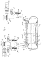
- the device shown in Fig. 1 is used for mounting a pneumatic tire 1 on a rim 1 of a motor vehicle wheel.
- Such a holding device is for example made DT 2105454 known.
- the rim 1 or the disc wheel is in the mounting device shown in FIG. 1 in horizontal Position with vertical axle 23 arranged.
- the Assembly tool consists of two tool parts, namely one Mounting roller 3 and a tire deflector 4.
- the assembly tool can also have two mounting rollers.
- the mounting roller 3 and the tire deflector 4 are at a common Carrier 9 of the guide device 19 continuously in the direction the wheel axle 23 mounted adjustable.
- a set screw 24 which is rotated by an electric actuator 8 can be.
- an adjusting screw 25 which of an electric actuator 6 is rotated.
- the actuators and the two tool parts (mounting roller 3 and tire deflector 4) are mounted on the common carrier 9.
- the mounting roller 3 is for this purpose on an associated carrier 7, on which the adjusting device (screw 24) for axial displacement of the mounting roller 3 attacks, rotatably mounted.
- the adjusting device screw 24
- the axial Adjustment device adjusting screw 25
- both the mounting roller as also the tire deflector 4 separately and independently be brought into desired axial positions.
- Tire deflector 4 ensures that during the assembly process of Overlying tire bead over the overhead rim flange 20 is performed.
- the axial positioning of the tire deflector 4 takes place as a function of the axial position of the overhead rim flange 20 and in particular depending from the axial distance of the uppermost rim flange 20 to Hump 17 or 18.
- the axial adjustment is done with the help the driven by the electric drive 6 screw 25, with which the carrier 5 and attached thereto Tire deflector are continuously adjusted in the axial direction can.
- the illustrated device further has a second guide device 15 for a trained as hold-down 11 Positioning.
- the hold-down 11 is used for fixing the axial position of the beginning of the assembly process over the Hump 17 or 18 away in the rim well bed pressed bead part of the pneumatic tire to be mounted. 2 By holding down 11 is ensured that during of the assembly process of the respectively over the Hump 17 or 18 in the rim well bed pushed bead part of the pneumatic tire 2 in this axial position remains until the assembly process finished.
- the hold-down 11 is attached to a support 12, on which an adjusting device for axial positioning the hold-down 11 in the form of a set screw 13 attacks.
- the adjusting screw 13 is powered by an electric Actuator 14 driven.
- the from the electrical Actuator 14 and the screw 13 existing adjustment is together with the carrier 12 and the hold-down 11 fixed to a support of the guide device 15.
- the carrier of the guide device 15 can in his Radial positioning depending on the rim diameter by means of an electric actuator 16 and thereby driven set screw 27 continuously adjusted become.
- a not shown Control device provided for the various actuators into which the axial positions of the humps 17 or 18 entered on the consecutive disk wheels become.
- the Wheel types can by appropriate encodings, which at the wheels are provided to be detected by machine.
- This inward radial movement can be achieved through the formed by the actuator 16 and the screw 27 Adjustment be effected (left embodiment in Fig. 2).
- this radial Adjustment by a pivoting movement of the hold-down 11 to cause a fulcrum 28 (right embodiment in Fig. 2).
- the actuator 14 and the screw 13, which for the axial adjustment of the Hold-down 11 serve, mitverschwenkt.
- the pivoting can be effected by a piston / cylinder assembly 29.
- the piston / cylinder arrangement is of the not shown Control device then actuated when the hold-down 11 brought into the respective in Fig. 2 axial position is.
- the piston / cylinder assembly 29 can also an electric actuator for pivoting of the hold 11 are used.
- the radial adjustment of the hold 11 can also by the combined actuation of the actuator 16 and the adjusting screw 27 with the pivoting about the pivot point 28 take place (right embodiment in Fig. 2).
- the hold-down 11 may, depending on the tire stiffness in the in the vertical arrangement shown in FIG. 1, for example 10 mm lower than the mounting roller 3, with which the circumferential mounting pressure on the overhead Side wall of the pneumatic tire 2 applied during the assembly process becomes.
- the axial positioning of the mounting roller 3 and the Hold-down 11 are chosen so that the top Tire bead certainly under the respective hump 17 or 18 of the successive disc wheels is pressed.
- Of the underlying tire bead lies inside at the bottom Rim horn 21, as can be seen from the figures is.
- the wheel becomes unfilled Tires brought to the filling station.
- the underlying tire bead is located in the Tire bead seat on the rim flange 21.
- the filled Pneumatic tire then takes the dashed lines in Fig. 1 shown Position on the rim 1 a.
Landscapes
- Engineering & Computer Science (AREA)
- Mechanical Engineering (AREA)
- Tires In General (AREA)
- Tyre Moulding (AREA)
- Automobile Manufacture Line, Endless Track Vehicle, Trailer (AREA)
- Testing Of Balance (AREA)
Abstract
Description
- Fig. 1
- in schnittbildlicher Darstellung ein Ausführungsbeispiel der Erfindung;
- Fig. 2
- zwei Ausführungsbeispiele zur Einstellung der radialen Position eines Niederhalters; und
- Fig. 3
- radiale Positionierungen des Niederhalters für zwei unterschiedliche axiale Positionen eines Humps an der Felge.
- 1
- Felge
- 2
- Luftreifen
- 3
- Montagerolle
- 4
- Reifenabweiser
- 5
- Träger für den Reifenabweiser
- 6
- Stellantrieb für den Reifenabweiser
- 7
- Träger für die Montagerolle
- 8
- Stellantrieb für die Montagerolle
- 9
- gemeinsamer Träger
- 10
- Stellantrieb für den Radius der Führungs-Kreisbahn des Montagewerkzeugs (Montage-Rolle 3 und Reifenabweiser 4)
- 11
- Niederhalter
- 12
- Träger für den Niederhalter
- 13
- Stellschraube für den Niederhalter
- 14
- Stellantrieb
- 15
- Führungseinrichtung
- 16
- Stellantrieb für die radiale Position der Führungseinrichtung 15
- 17
- Hump
- 18
- Hump
- 19
- Führungseinrichtung
- 20
- oben liegendes Felgenhorn
- 21
- unten liegendes Felgenhorn
- 22
- Halter
- 23
- Radachse
- 24
- Stellschraube für die Montagerolle
- 25
- Stellschraube für den Reifenabweiser
- 26
- Stellschraube für die Führungseinrichtung 19
- 27
- Stellschraube für den radialen Abstand des Niederhalters 11 von der Radachse 23
- 28
- Drehpunkt
- 29
- Kolben-/Zylinderanordnung
- 30
- Teil des Niederhalters
- 31
- Umfangsrand des Felgenhorns 20
Claims (12)
- Verfahren zum Montieren eines Luftreifens auf eine Felge eines Kraftfahrzeugrades, bei dem der eine Reifenwulst am einen Felgenhorn und der andere Reifenwulst am Hump der festgehaltenen Felge mittels eines Montagevorgangs, bei dem ein auf einer Kreisbahn um die Radachse geführter und in axialer Richtung wirkender Druck auf die eine Seitenwand des Luftreifens ausgeübt wird, angeordnet werden, wobei bei Beginn des Montagevorgangs ein Teil des Reifenwulst in die gewünschte axiale Position über den Hump in das Felgentiefbett gebracht ist und in dieser Position während des weiteren sich anschließenden Montagevorgangs durch eine Niederhalterkraft niedergehalten wird,
dadurch gekennzeichnet, dass die axiale Position der Stelle, an welcher die Niederhaltekraft in den niedergehaltenen Teilen des Reifenwulstes eingeleitet wird, in Abhängigkeit von der axialen Lage des Humps an der Felge für die Montagevorgänge an aufeinanderfolgenden Rädern variabel eingestellt wird. - Verfahren nach Anspruch 1,
dadurch gekennzeichnet, dass die Niederhaltekraft auf den niedergehaltenen Teil des Reifenwulstes an einer Stelle eingeleitet wird, welche gegenüber der Radachse auf einem kleineren Radius liegt als der äußere Umfang des Felgenhorns. - Verfahren nach Anspruch 1 oder 2,
dadurch gekennzeichnet, dass die axiale Position der Kreisbahn, entlang welcher der Montagevorgang durchgeführt wird, in Abhängigkeit von der axialen Lage des Humps an der Felge für die Montagevorgänge an aufeinanderfolgenden Rädern variabel eingestellt wird. - Vorrichtung zum Montieren eines Luftreifens auf eine Felge eines Kraftfahrzeugrades, mit einer Halteeinrichtung zum Festhalten der Felge, einer ersten Führungseinrichtung zum Führen wenigstens eines Montagewerkzeugs entlang einer Kreisbahn um die Achse der festgehaltenen Felge und einer zweiten Führungseinrichtung für einen Niederhalter (11), durch welchen ein in axialer Richtung über den Hump (17, 18) in das Felgentiefbett bei Beginn des Montagevorgangs bewegtes Wulstteil des Luftreifens (2) während des weiteren Montagevorgangs in dieser axialen Position niedergehalten wird,
dadurch gekennzeichnet, dass die zweite Führun gseinrichtung (15) eine Einstelleinrichtung (12 bis 14) für die Einstellung der axialen Position des Niederhalters (11) aufweist. - Vorrichtung nach Anspruch 4,
dadurch gekennzeichnet, dass die zweite Führungseinrichtung (15) ferner eine Einstelleinrichtung (16, 27; 28, 29) für eine radiale Position des Niederhalters (11) aufweist. - Vorrichtung nach Anspruch 4 oder 5,
dadurch gekennzeichnet, dass die radiale Position des auf den niederzuhaltenden Wulstteil aufsetzbaren Teils (30) des Niederhalters (11) während des Niederhaltens einen geringeren Abstand zur Radachse (23) aufweist als der äußere Umfangsrand (31) des Felgenhorns (20). - Vorrichtung nach einem der Ansprüche 4 bis 6,
dadurch gekennzeichnet, dass die erste Führungseinrichtung (19) eine Einstelleinrichtung (5 bis 8), mit welcher die axiale Position der Kreisbahn, auf welcher das wenigstens eine Montagewerkzeug (3, 4) geführt wird, in Abhängigkeit von der jeweiligen axialen Lage des Humps (17, 18) an der festgehaltenen Felge (1) einstellbar ist. - Vorrichtung nach Anspruch 7,
dadurch gekennzeichnet, dass die erste Führungseinrichtung (19) einen Träger (5, 7) aufweist, mit welchem das wenigstens eine Montagewerkzeug (3, 4) auf der Kreisbahn geführt wird. - Vorrichtung nach Anspruch 7 oder 8,
dadurch gekennzeichnet, dass die Einstelleinrichtung (5 bis 8) an der ersten Führungseinrichtung (19) einen Stellantrieb (6, 8) für wenigstens zwei Montagewerkzeuge (3, 4) aufweist. - Vorrichtung nach Anspruch 9,
dadurch gekennzeichnet, dass die erste Führungseinrichtung (19) für die Stellantriebe (6, 8) der jeweils zwei Montagewerkzeuge (3, 4) einen gemeinsamen Träger (9) aufweist. - Vorrichtung nach einem der Ansprüche 4 bis 10,
dadurch gekennzeichnet, dass die axiale Position des wenigstens einen Montagewerkzeugs (3, 4) und/oder des Niederhalters (11) stufenlos einstellbar ist. - Vorrichtung nach einem der Ansprüche 4 bis 11,
dadurch gekennzeichnet, dass die Felge (2) beim Montagevorgang in einer horizontalen Position festgehalten ist.
Applications Claiming Priority (2)
| Application Number | Priority Date | Filing Date | Title |
|---|---|---|---|
| DE10222164A DE10222164C1 (de) | 2002-05-17 | 2002-05-17 | Vorrichtung zum Montieren eines Luftreifens auf eine Felge eines Kraftfahrzeugrades |
| DE10222164 | 2002-05-17 |
Publications (3)
| Publication Number | Publication Date |
|---|---|
| EP1362717A2 true EP1362717A2 (de) | 2003-11-19 |
| EP1362717A3 EP1362717A3 (de) | 2004-01-07 |
| EP1362717B1 EP1362717B1 (de) | 2007-04-11 |
Family
ID=27798295
Family Applications (1)
| Application Number | Title | Priority Date | Filing Date |
|---|---|---|---|
| EP03003918A Expired - Lifetime EP1362717B1 (de) | 2002-05-17 | 2003-02-21 | Verfahren und Vorrichtung zum Montieren eines Luftreifens auf eine Felge eines Kraftfahrzeugrades |
Country Status (5)
| Country | Link |
|---|---|
| EP (1) | EP1362717B1 (de) |
| AT (1) | ATE359186T1 (de) |
| DE (2) | DE10222164C1 (de) |
| ES (1) | ES2284994T3 (de) |
| PT (1) | PT1362717E (de) |
Cited By (1)
| Publication number | Priority date | Publication date | Assignee | Title |
|---|---|---|---|---|
| CN105291726A (zh) * | 2014-05-30 | 2016-02-03 | 施耐宝仪器股份有限公司 | 轮胎安装工具总成 |
Families Citing this family (4)
| Publication number | Priority date | Publication date | Assignee | Title |
|---|---|---|---|---|
| DE102004040866A1 (de) | 2004-08-23 | 2006-03-02 | Schenck Rotec Gmbh | Vorrichtung und Verfahren zum Montieren eines Reifens |
| DE102006050968B3 (de) * | 2006-10-28 | 2008-07-17 | Schenck Rotec Gmbh | Vorrichtung zum Aufziehen eines Reifens auf eine Felge eines Fahrzeugrades |
| DE102009014285B4 (de) * | 2009-03-25 | 2011-02-17 | Schenck Rotec Gmbh | Verfahren zur Montage eines Reifens und Vorrichtung zur Durchführung des Verfahrens |
| DE102020116910A1 (de) | 2020-06-26 | 2021-12-30 | Bayerische Motoren Werke Aktiengesellschaft | Fahrzeugdach sowie Fahrzeug |
Family Cites Families (5)
| Publication number | Priority date | Publication date | Assignee | Title |
|---|---|---|---|---|
| FR996319A (fr) * | 1948-09-28 | 1951-12-18 | Brockhouse J & Co Ltd | Perfectionnements apportés aux procédés et aux dispositifs pour le montage des bandages pneumatiques |
| DE1933653A1 (de) * | 1968-08-02 | 1970-02-26 | Quilez D Juan Jose Mas | Runder Steckeruntersatz fuer Vielfachanschluss |
| DE7031177U (de) * | 1970-08-20 | 1970-12-10 | Preissner Hans | Reifenmontiermaschine. |
| US4830079A (en) * | 1982-12-30 | 1989-05-16 | Toyota Jidosha Kabushiki Kaisha | Method and apparatus for mounting tires on wheels |
| IT1310201B1 (it) * | 1999-03-31 | 2002-02-11 | G S Srl | Dispositivo per agevolare lo smontaggio e il montaggio di pneumatici. |
-
2002
- 2002-05-17 DE DE10222164A patent/DE10222164C1/de not_active Expired - Fee Related
-
2003
- 2003-02-21 EP EP03003918A patent/EP1362717B1/de not_active Expired - Lifetime
- 2003-02-21 ES ES03003918T patent/ES2284994T3/es not_active Expired - Lifetime
- 2003-02-21 DE DE50306991T patent/DE50306991D1/de not_active Expired - Lifetime
- 2003-02-21 AT AT03003918T patent/ATE359186T1/de active
- 2003-02-21 PT PT03003918T patent/PT1362717E/pt unknown
Cited By (2)
| Publication number | Priority date | Publication date | Assignee | Title |
|---|---|---|---|---|
| CN105291726A (zh) * | 2014-05-30 | 2016-02-03 | 施耐宝仪器股份有限公司 | 轮胎安装工具总成 |
| CN105291726B (zh) * | 2014-05-30 | 2018-03-23 | 施耐宝仪器股份有限公司 | 轮胎安装/拆卸工具总成以及安装支撑工具 |
Also Published As
| Publication number | Publication date |
|---|---|
| ES2284994T3 (es) | 2007-11-16 |
| EP1362717A3 (de) | 2004-01-07 |
| PT1362717E (pt) | 2007-07-06 |
| EP1362717B1 (de) | 2007-04-11 |
| DE10222164C1 (de) | 2003-10-02 |
| ATE359186T1 (de) | 2007-05-15 |
| DE50306991D1 (de) | 2007-05-24 |
Similar Documents
| Publication | Publication Date | Title |
|---|---|---|
| DE60302358T2 (de) | Reifenaufbautrommel mit umschlagvorrichtung und verfahren zur herstellung von rohreifen | |
| DE69815497T2 (de) | Reifendemontiervorrichtung und Zubehör | |
| EP3351313B1 (de) | Verfahren und vorrichtung zum drückwalzen | |
| EP1567365B1 (de) | Spannvorrichtung für felgen, insbesondere zur reifenmontage | |
| DE2505398A1 (de) | Verfahren und vorrichtung zum schleifen von reifen | |
| EP1362717B1 (de) | Verfahren und Vorrichtung zum Montieren eines Luftreifens auf eine Felge eines Kraftfahrzeugrades | |
| EP0792761A1 (de) | Vorrichtung zur Verbesserung des Laufverhaltens von Fahrzeugrädern durch Verbesserung des Sitzes der Wulstpartien auf der Felge | |
| DE10149086C1 (de) | Verfahren zum Herstellen eines Notlauf-Stützkörpers für Notlauf-Fahrzeugräder | |
| EP0556623A1 (de) | Runderneuerungsvorrichtung | |
| EP0191367B1 (de) | Verfahren und Vorrichtung zur Montage von Fahrzeugluftreifen | |
| EP3278894B1 (de) | Drückwalzmaschine und umformverfahren zum herstellen eines rades | |
| DE102005001212A1 (de) | Verfahren und Vorrichtung zur Montage eines Luftreifens | |
| EP3034287B1 (de) | Vorrichtung zur fertigung von kernpaketen für fahrzeugluftreifen | |
| EP1738937A2 (de) | Verfahren und Vorrichtung zur Montage eines Luftreifens | |
| EP3722115B1 (de) | Reifenfüllstation und zugehöriges betriebsverfahren | |
| DE2529343A1 (de) | Verfahren und vorrichtung zum montieren und demontieren von kraftfahrzeugreifen, insbesondere kraftfahrzeugreifen fuer lastkraftwagen | |
| EP2386406B1 (de) | Verfahren zum Herstellen eines Reifenrohlings | |
| DE4019992C2 (de) | Vorrichtung zur Reifensitzverbesserung von auf Scheibenrädern montierten Luftreifen bei Kraftfahrzeugrädern | |
| DE3344737C2 (de) | ||
| EP1564028B1 (de) | Matchmaschine | |
| DE3586860T2 (de) | Modelliertes fahrzeugrad. | |
| EP0307650A1 (de) | Montagevorrichtung für Reifen | |
| WO2003047891A1 (de) | Vorrichtung zur reifensitzoptimierung | |
| DE3733779C2 (de) | ||
| EP1447245B1 (de) | Vorrichtung zur Montage oder Demontage eines Notlaufstützkörpers für Reifen |
Legal Events
| Date | Code | Title | Description |
|---|---|---|---|
| PUAI | Public reference made under article 153(3) epc to a published international application that has entered the european phase |
Free format text: ORIGINAL CODE: 0009012 |
|
| AK | Designated contracting states |
Kind code of ref document: A2 Designated state(s): AT BE BG CH CY CZ DE DK EE ES FI FR GB GR HU IE IT LI LU MC NL PT SE SI SK TR |
|
| AX | Request for extension of the european patent |
Extension state: AL LT LV MK RO |
|
| PUAL | Search report despatched |
Free format text: ORIGINAL CODE: 0009013 |
|
| AK | Designated contracting states |
Kind code of ref document: A3 Designated state(s): AT BE BG CH CY CZ DE DK EE ES FI FR GB GR HU IE IT LI LU MC NL PT SE SI SK TR |
|
| AX | Request for extension of the european patent |
Extension state: AL LT LV MK RO |
|
| 17P | Request for examination filed |
Effective date: 20040129 |
|
| AKX | Designation fees paid |
Designated state(s): AT BE BG CH CY CZ DE DK EE ES FI FR GB GR HU IE IT LI LU MC NL PT SE SI SK TR |
|
| 17Q | First examination report despatched |
Effective date: 20050704 |
|
| GRAP | Despatch of communication of intention to grant a patent |
Free format text: ORIGINAL CODE: EPIDOSNIGR1 |
|
| GRAS | Grant fee paid |
Free format text: ORIGINAL CODE: EPIDOSNIGR3 |
|
| GRAA | (expected) grant |
Free format text: ORIGINAL CODE: 0009210 |
|
| AK | Designated contracting states |
Kind code of ref document: B1 Designated state(s): AT BE BG CH CY CZ DE DK EE ES FI FR GB GR HU IE IT LI LU MC NL PT SE SI SK TR |
|
| PG25 | Lapsed in a contracting state [announced via postgrant information from national office to epo] |
Ref country code: SI Free format text: LAPSE BECAUSE OF FAILURE TO SUBMIT A TRANSLATION OF THE DESCRIPTION OR TO PAY THE FEE WITHIN THE PRESCRIBED TIME-LIMIT Effective date: 20070411 Ref country code: FI Free format text: LAPSE BECAUSE OF FAILURE TO SUBMIT A TRANSLATION OF THE DESCRIPTION OR TO PAY THE FEE WITHIN THE PRESCRIBED TIME-LIMIT Effective date: 20070411 |
|
| REG | Reference to a national code |
Ref country code: GB Ref legal event code: FG4D Free format text: NOT ENGLISH |
|
| REG | Reference to a national code |
Ref country code: CH Ref legal event code: EP |
|
| REG | Reference to a national code |
Ref country code: IE Ref legal event code: FG4D Free format text: LANGUAGE OF EP DOCUMENT: GERMAN |
|
| REF | Corresponds to: |
Ref document number: 50306991 Country of ref document: DE Date of ref document: 20070524 Kind code of ref document: P |
|
| REG | Reference to a national code |
Ref country code: PT Ref legal event code: SC4A Free format text: AVAILABILITY OF NATIONAL TRANSLATION Effective date: 20070626 |
|
| GBT | Gb: translation of ep patent filed (gb section 77(6)(a)/1977) |
Effective date: 20070627 |
|
| REG | Reference to a national code |
Ref country code: SE Ref legal event code: TRGR |
|
| ET | Fr: translation filed | ||
| REG | Reference to a national code |
Ref country code: ES Ref legal event code: FG2A Ref document number: 2284994 Country of ref document: ES Kind code of ref document: T3 |
|
| REG | Reference to a national code |
Ref country code: IE Ref legal event code: FD4D |
|
| PG25 | Lapsed in a contracting state [announced via postgrant information from national office to epo] |
Ref country code: DK Free format text: LAPSE BECAUSE OF FAILURE TO SUBMIT A TRANSLATION OF THE DESCRIPTION OR TO PAY THE FEE WITHIN THE PRESCRIBED TIME-LIMIT Effective date: 20070411 Ref country code: IE Free format text: LAPSE BECAUSE OF FAILURE TO SUBMIT A TRANSLATION OF THE DESCRIPTION OR TO PAY THE FEE WITHIN THE PRESCRIBED TIME-LIMIT Effective date: 20070411 Ref country code: BG Free format text: LAPSE BECAUSE OF FAILURE TO SUBMIT A TRANSLATION OF THE DESCRIPTION OR TO PAY THE FEE WITHIN THE PRESCRIBED TIME-LIMIT Effective date: 20070711 |
|
| PLBE | No opposition filed within time limit |
Free format text: ORIGINAL CODE: 0009261 |
|
| STAA | Information on the status of an ep patent application or granted ep patent |
Free format text: STATUS: NO OPPOSITION FILED WITHIN TIME LIMIT |
|
| 26N | No opposition filed |
Effective date: 20080114 |
|
| PG25 | Lapsed in a contracting state [announced via postgrant information from national office to epo] |
Ref country code: GR Free format text: LAPSE BECAUSE OF FAILURE TO SUBMIT A TRANSLATION OF THE DESCRIPTION OR TO PAY THE FEE WITHIN THE PRESCRIBED TIME-LIMIT Effective date: 20070712 |
|
| REG | Reference to a national code |
Ref country code: CH Ref legal event code: PL |
|
| PG25 | Lapsed in a contracting state [announced via postgrant information from national office to epo] |
Ref country code: LI Free format text: LAPSE BECAUSE OF NON-PAYMENT OF DUE FEES Effective date: 20080229 Ref country code: CH Free format text: LAPSE BECAUSE OF NON-PAYMENT OF DUE FEES Effective date: 20080229 Ref country code: MC Free format text: LAPSE BECAUSE OF NON-PAYMENT OF DUE FEES Effective date: 20080228 |
|
| PG25 | Lapsed in a contracting state [announced via postgrant information from national office to epo] |
Ref country code: EE Free format text: LAPSE BECAUSE OF FAILURE TO SUBMIT A TRANSLATION OF THE DESCRIPTION OR TO PAY THE FEE WITHIN THE PRESCRIBED TIME-LIMIT Effective date: 20070411 |
|
| PG25 | Lapsed in a contracting state [announced via postgrant information from national office to epo] |
Ref country code: CY Free format text: LAPSE BECAUSE OF FAILURE TO SUBMIT A TRANSLATION OF THE DESCRIPTION OR TO PAY THE FEE WITHIN THE PRESCRIBED TIME-LIMIT Effective date: 20070411 |
|
| PG25 | Lapsed in a contracting state [announced via postgrant information from national office to epo] |
Ref country code: LU Free format text: LAPSE BECAUSE OF NON-PAYMENT OF DUE FEES Effective date: 20080221 Ref country code: HU Free format text: LAPSE BECAUSE OF FAILURE TO SUBMIT A TRANSLATION OF THE DESCRIPTION OR TO PAY THE FEE WITHIN THE PRESCRIBED TIME-LIMIT Effective date: 20071012 |
|
| REG | Reference to a national code |
Ref country code: FR Ref legal event code: PLFP Year of fee payment: 14 |
|
| REG | Reference to a national code |
Ref country code: FR Ref legal event code: PLFP Year of fee payment: 15 |
|
| REG | Reference to a national code |
Ref country code: FR Ref legal event code: PLFP Year of fee payment: 16 |
|
| PGFP | Annual fee paid to national office [announced via postgrant information from national office to epo] |
Ref country code: NL Payment date: 20180221 Year of fee payment: 16 |
|
| PGFP | Annual fee paid to national office [announced via postgrant information from national office to epo] |
Ref country code: ES Payment date: 20180322 Year of fee payment: 16 Ref country code: CZ Payment date: 20180208 Year of fee payment: 16 Ref country code: GB Payment date: 20180221 Year of fee payment: 16 |
|
| PGFP | Annual fee paid to national office [announced via postgrant information from national office to epo] |
Ref country code: FR Payment date: 20180221 Year of fee payment: 16 Ref country code: SE Payment date: 20180222 Year of fee payment: 16 Ref country code: IT Payment date: 20180221 Year of fee payment: 16 Ref country code: SK Payment date: 20180208 Year of fee payment: 16 Ref country code: TR Payment date: 20180220 Year of fee payment: 16 Ref country code: AT Payment date: 20180220 Year of fee payment: 16 Ref country code: BE Payment date: 20180221 Year of fee payment: 16 Ref country code: PT Payment date: 20180207 Year of fee payment: 16 |
|
| REG | Reference to a national code |
Ref country code: SE Ref legal event code: EUG |
|
| REG | Reference to a national code |
Ref country code: NL Ref legal event code: MM Effective date: 20190301 |
|
| REG | Reference to a national code |
Ref country code: AT Ref legal event code: MM01 Ref document number: 359186 Country of ref document: AT Kind code of ref document: T Effective date: 20190221 |
|
| GBPC | Gb: european patent ceased through non-payment of renewal fee |
Effective date: 20190221 |
|
| PG25 | Lapsed in a contracting state [announced via postgrant information from national office to epo] |
Ref country code: CZ Free format text: LAPSE BECAUSE OF NON-PAYMENT OF DUE FEES Effective date: 20190221 Ref country code: PT Free format text: LAPSE BECAUSE OF NON-PAYMENT OF DUE FEES Effective date: 20190821 Ref country code: SE Free format text: LAPSE BECAUSE OF NON-PAYMENT OF DUE FEES Effective date: 20190222 Ref country code: SK Free format text: LAPSE BECAUSE OF NON-PAYMENT OF DUE FEES Effective date: 20190221 |
|
| REG | Reference to a national code |
Ref country code: SK Ref legal event code: MM4A Ref document number: E 2021 Country of ref document: SK Effective date: 20190221 |
|
| REG | Reference to a national code |
Ref country code: BE Ref legal event code: MM Effective date: 20190228 |
|
| PG25 | Lapsed in a contracting state [announced via postgrant information from national office to epo] |
Ref country code: AT Free format text: LAPSE BECAUSE OF NON-PAYMENT OF DUE FEES Effective date: 20190221 |
|
| PG25 | Lapsed in a contracting state [announced via postgrant information from national office to epo] |
Ref country code: NL Free format text: LAPSE BECAUSE OF NON-PAYMENT OF DUE FEES Effective date: 20190301 Ref country code: GB Free format text: LAPSE BECAUSE OF NON-PAYMENT OF DUE FEES Effective date: 20190221 |
|
| PG25 | Lapsed in a contracting state [announced via postgrant information from national office to epo] |
Ref country code: BE Free format text: LAPSE BECAUSE OF NON-PAYMENT OF DUE FEES Effective date: 20190228 Ref country code: FR Free format text: LAPSE BECAUSE OF NON-PAYMENT OF DUE FEES Effective date: 20190228 Ref country code: IT Free format text: LAPSE BECAUSE OF NON-PAYMENT OF DUE FEES Effective date: 20190221 |
|
| REG | Reference to a national code |
Ref country code: ES Ref legal event code: FD2A Effective date: 20200331 |
|
| PG25 | Lapsed in a contracting state [announced via postgrant information from national office to epo] |
Ref country code: ES Free format text: LAPSE BECAUSE OF NON-PAYMENT OF DUE FEES Effective date: 20190222 |
|
| PGFP | Annual fee paid to national office [announced via postgrant information from national office to epo] |
Ref country code: DE Payment date: 20210303 Year of fee payment: 19 |
|
| PG25 | Lapsed in a contracting state [announced via postgrant information from national office to epo] |
Ref country code: TR Free format text: LAPSE BECAUSE OF NON-PAYMENT OF DUE FEES Effective date: 20190221 |
|
| REG | Reference to a national code |
Ref country code: DE Ref legal event code: R119 Ref document number: 50306991 Country of ref document: DE |
|
| PG25 | Lapsed in a contracting state [announced via postgrant information from national office to epo] |
Ref country code: DE Free format text: LAPSE BECAUSE OF NON-PAYMENT OF DUE FEES Effective date: 20220901 |