EP1362358B1 - kOLLEKTOR MIT EINER KOLLEKTORWAND UND EINER KOLLEKTORSPULENGRUPPE FÜR EIN GYROTRON - Google Patents
kOLLEKTOR MIT EINER KOLLEKTORWAND UND EINER KOLLEKTORSPULENGRUPPE FÜR EIN GYROTRON Download PDFInfo
- Publication number
- EP1362358B1 EP1362358B1 EP02708289A EP02708289A EP1362358B1 EP 1362358 B1 EP1362358 B1 EP 1362358B1 EP 02708289 A EP02708289 A EP 02708289A EP 02708289 A EP02708289 A EP 02708289A EP 1362358 B1 EP1362358 B1 EP 1362358B1
- Authority
- EP
- European Patent Office
- Prior art keywords
- collector
- wall
- rotation
- recess
- symmetric
- Prior art date
- Legal status (The legal status is an assumption and is not a legal conclusion. Google has not performed a legal analysis and makes no representation as to the accuracy of the status listed.)
- Expired - Lifetime
Links
Images

Classifications
-
- H—ELECTRICITY
- H01—ELECTRIC ELEMENTS
- H01J—ELECTRIC DISCHARGE TUBES OR DISCHARGE LAMPS
- H01J25/00—Transit-time tubes, e.g. klystrons, travelling-wave tubes, magnetrons
- H01J25/02—Tubes with electron stream modulated in velocity or density in a modulator zone and thereafter giving up energy in an inducing zone, the zones being associated with one or more resonators
- H01J25/025—Tubes with electron stream modulated in velocity or density in a modulator zone and thereafter giving up energy in an inducing zone, the zones being associated with one or more resonators with an electron stream following a helical path
-
- H—ELECTRICITY
- H01—ELECTRIC ELEMENTS
- H01J—ELECTRIC DISCHARGE TUBES OR DISCHARGE LAMPS
- H01J23/00—Details of transit-time tubes of the types covered by group H01J25/00
- H01J23/02—Electrodes; Magnetic control means; Screens
- H01J23/027—Collectors
Definitions
- the invention relates to a collector with a collector wall and a collector coil group for a gyrotron.
- the coil group is to the axis of Gyrotrons mounted coaxially in the collector area. With her will in the region of the collector a rotationally symmetrical to the axis Magnetic field of localized strength, or with a given generated axial field strength course, with the impact area on the inner wall of the collector of the gyrotron produced Electron hollow beam set in a predetermined range can be.
- the remaining energy of the electron beam is on the Wall of the collector dissipates.
- the trajectories of the electron beam are due to the course of magnetic flux surfaces essentially determined.
- the main problems of a collector in A high performance gyrotron consist in the distribution of Beam power along the collector surface.
- the impact area of the hollow electron beam on the inner wall of the collector Moved back and forth over an axial range, also called wobble. This is so far by the in cylindrical, coaxial generated outside around the collector mounted collector coils, to the axis rotationally symmetric magnetic field causes. To do this the corresponding collector coils with a and / or AC energized.
- the sweep or pulsation frequency is in existing gyrotron systems by the skin effect to typically about 10 Hz limited, depending on the thickness of the collector wall.
- the Wall thickness is in high performance gyrotrons because of the high power densities typically 10 mm. Because of the large diameter the collector of such a gyrotron - about 400 mm and more - reach the collector partially enveloping the collector coils considerable dimensions.
- the coil group of this collector consists of at least one solenoidalen coil, to the axis in the collector region coaxially mounted. With this coil group can be used to form a rotationally symmetric electron beam necessary, rotationally symmetric Magnetic field course can be adjusted along the axis.
- the task is achieved by the coaxial installation of a collector coil group from at least one cylindrical coil in the collector according to the characterizing features of claim 1 of Structure solved.
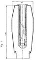
- the collector wall has the final one Front side a hollow cylindrical to the axis coaxial Dent, in which the collector coil group, on a cylindrical coil winding body sitting, inserted and centered is anchored.
- the magnetic field generating coils whose Dimensioning and position on the axis calculated is axially behind one another and / or radially one above the other.
- the coils are energized and generate in their Entity a resulting, rotationally symmetric to the axis Magnetic field with predetermined axial course of the magnetic field strength, so that the rotationally symmetrical hollow electron beam at this indentation at least with their free-standing Start area passed collision-free and in a intended impingement on the collector inner wall becomes.
- the hollow cylindrical Indentation in which the collector coil group is sunk can be included in an external cooling circuit.
- the hollow cylindrical coil winding body passes at least a concentric tube. The only or the outer of several at least touched the bottom of the indentation. Because of this outer pipe and the wall of the indentation can be at the collector coil group past at radial passages at the end of winding-free bobbin at the bottom of the indentation and / or at Passages through the bobbin itself a flow channel for a coolant can be set up when the outer pipe and the Wall of the indentation connected to the external cooling circuit become.
- the rotationally symmetric Impact area on the inner wall of the collector kept deliberately large, so that the impinging electron density and the resulting specific burden on Collector wall remains at least tolerable or technically is still acceptable.
- This is basically done by that the coils are energized only with direct current and thereby a temporally constant, spatially non-adiabatic magnetic field is generated with predetermined axial field strength, because Electron hollow beam on the one hand rotationally symmetrical shapes and the impact area of the electron expands, causing the impinging Electron density and thus the power density in the impact area on the inner wall of the collector on at least the technically tolerable level is limited.
- impact area come at most the outer shell wall, the front wall and the Surface of the indentation of the collector into consideration. In this Gleichstromerregten case needs the wall thickness of the indentation not be thin, because the magnetic field does not pulse in time and so that no skin effect occurs.
- a time-pulsating magnetic field is used for periodically reciprocating the position of the impact area on the inner wall of the collector.
- one or more coils of the coil group are energized in addition to the respective alternating current with a respective predetermined direct current in order to set a required rotationally symmetrical shaping of the electron hollow beam.
- the hollow electron beam with its impressed radial extent when passing through the pulsating magnetic field in the collector region, pulses in time with the AC frequency in such a way that its annular coaxial impact area at most between two axial positions on the shell wall of the collector or between two radial positions on the end wall, wherein both radial positions always have a larger radius than that of the recess, or between a position on the shell wall of the collector and a radial position outside the recess on the front of the collector migrates back and forth in the rhythm of the AC frequency.
- the design is not limited to single-stage preload. It can also be similar for non-preloaded as well as for multi-level, for example, two-stage biased collectors be performed.
- the contour dimensions of the coaxial collector are here, for example: largest clear width 520 mm, length 1360 mm.
- the hollow cylindrical recess of the local collector wall which, as elsewhere, is preferably made of copper is, other, technically suitable materials are not excluded, there but in contrast to the outer wall with here 10 mm has only 3 mm wall thickness, because there is no load through the Electron hollow beam occurs.
- This indentation is on the Welded front wall of the collector or soldered hard. For pure experimenting can be useful if the Indentation with a flange on the front wall also vacuum-tight can be screwed.
- the collector coil group wound on a bobbin, pushed in and on the ground and centered on the collector front wall.
- the coil group exists here four solenoids, a first with a thick wrap, the Resonator output closest. At this closes another internal solenoid with a weaker winding than the former to the front wall, on a bobbin sits with a greater width.
- This second solenoids pushed two more solenoids, each with a thinner winding, partially encasing the second solenoids and themselves overlap yourself.
- the first solenoid is provided to wobble during operation Electron beam so pendulum impact area on the collector, with a direct current and added alternating current energized become.
- the three other solenoids are here only with alternating current be excited.
- the exciter currents are an example in the listed below. Depending on the design and the amount of field strength along the axis may be different Coil dimensions and excitation currents necessary.
- the collector coil group is via a flange on the end wall screwed on the collector and at the bottom of the indentation centered over a Flanscheinbau.
- the Flanscheinbau has radial Holes, so that a cooling circuit can be set up, in which the coolant, the inner wall of the recess and the Coil group touched surface.
- the example coil parameters are summarized below in the table for this design.
- the details are geometric dimensions of the partial coils.
- the axial displacement of the impact area of the electron beam and the expansion and contraction is effected by applying an alternating current to the coils.
- the coil at the bottom of the indentation (COL4 in the table) is additionally excited with a direct current of 100 A / cm 2 .
- the total power for the collector coils is about 1.5 kW, assuming a fill factor of 0.5 for the windings.
- With the wall thickness of 3 mm a pulsation up to about 50 Hz is possible.
- the skin penetration depth of 9.28 mm at 50 Hz is reflected by an attenuation of the magnetic field collector space by 28%.
Landscapes
- Microwave Tubes (AREA)
Description
zwischen zwei axialen Positionen auf der Mantelwand des Kollektors oder
zwischen zwei radialen Positionen auf der Stirnwand, wobei beide radialen Positionen stets einen größeren Radius als den der Einbuchtung haben, oder
zwischen einer Position auf der Mantelwand des Kollektors und einer radialen Position außerhalb der Einbuchtung auf der Stirn des Kollektors
in dem Rhythmus der Wechselstromfrequenz hin und her wandert.
- Die geringere Wandstärke der Kapselung der Kollektorspulengruppe lässt wegen des Skineffekts ein Pulsieren des Magnetfeldes mit höherer Frequenz zu. Eine geringere Stärke der Wand kann gewählt werden, weil sie nicht vom primären Elektronenstrahl getroffen wird und daher nur eine geringe thermische Belastung erfährt.
- Das höherfrequente Pulsieren des durch die Spulengruppe erzeugten Magnetfelds bewirkt entsprechend ein schnelleres Hinundherwandern zwischen zwei Endpositionen des Auftreffgebiets des Elektronenhohlstrahls auf der Innenwand des Kollektors. Damit lässt sich die Amplitude der Oszillationen der Oberflächentemperatur erniedrigen.
- Die Abmessungen der innen liegenden Spulengruppe ist wesentlich kleiner als die einer entsprechend leistungsfähigen außen liegenden. Daher wird das Gewicht und der Leistungsverbrauch der Kollektorspulengruppe erheblich reduziert.
| Spule | Zm/cm | Rm/cm | dz/cm | dr/cm | j/A/cm2 |
| COL 1 | 93.0 | 6.80 | 88.0 | 1.8 | j1coll |
| COL 2 | 93.0 | 7.85 | 68.0 | 0.3 | j2coll |
| COL 3 | 103.0 | 8.30 | 60.0 | 0.6 | j3coll |
| COL 4 | 43.0 | 6.80 | 12.0 | 3.6 | j4coll + j4dc |
Claims (4)
- Kollektor mit einer Kollektorwand und einer Kollektorspulengruppe für eine Gyrotron, wobei die Kollektorspulengruppe aus mindestens einer solenoidalen Spule besteht, die zu der Achse im Kollektorbereich koaxial angebracht ist, mit der der zur Formung des rotationssymmetrischen Elektronenhohlstrahls notwendige, mit ihr erzeugte rotationssymmetrische Magnetfeldverlauf entlang der Achse eingestellt werden kann, dadurch gekennzeichnet, dass die Kollektorwand von der abschließenden Stirnseite her ins Kollektorinnere eine zu der Achse koaxiale hohlzylindrische Einbuchtung hat, in die die Kollektorspulengruppe, auf einem zylindrischen Spulenwickelkörper sitzend, eingeschoben und zentriert ist, und
die magnetfelderzeugenden Spulen axial hintereinander und/oder radial übereinander gewickelt sind, so dass, mit dem jeweils vorgegebenen elektrischen Strom erregt, ein axialer Verlauf der Magnetfeldstärke über die Länge des Kollektors derart eingestellt werden kann, dass der rotationssymmetrische Elektronenhohlstrahl eingeprägter radialer Ausdehnung in einen vorgesehenen rotationssymmetrischen Auftreffbereich auf der Innenseite der Kollektorwand gelenkt wird. - Kollektor nach Anspruch 1,dadurch gekennzeichnet, dass durch den hohlzylindrischen Spulenwickelkörper hindurch mindestens ein konzentrisches Rohr ragt und zumindest das äußere den Boden der Einbuchtung fluiddicht berührt, so dass dieses und die Wand der Einbuchtung in einen Kühlmittelkreislauf einbezogen werden kann.
- Verfahren zum elektrischen Betreiben des Kollektors nach einem der Ansprüche 1 bis 2, dadurch gekennzeichnet, dass die Spulen der Kollektorspulengruppe jeweils mit einem vorgegebenen Gleichstrom derart erregt werden, dass der rotationssymmetrische Elektronenhohlstrahl eingeprägter radialer Ausdehnung beim Durchlaufen des dadurch erzeugten Magnetfelds im Kollektorraum rotationssymmetrisch geformt wird, und zwar derart, dass sich seine Auftrefffläche auf dem Kollektor höchstens über die äußere Mantelwand, die Stirnwand und die Mantelwand der Einbuchtung erstreckt.
- Verfahren zum elektrischen Betreiben des Kollektors nach einem der Ansprüche 1 bis 2, dadurch gekennzeichnet, dass die Spulen der Kollektorspulengruppe mit einem Wechselstrom vorgegebener Amplitude und Frequenz und mit einem Gleichstrom vorgegebener Stromstärke erregt werden, so dass der rotationssymmetrische Elektronenhohlstrahl eingeprägter radialer Ausdehnung beim Durchlaufen des dadurch erzeugten pulsierenden Magnetfelds rotationssymmetrisch derart pulsierend geformt wird, dass sein ringförmiges koaxiales Auftreffgebiet höchstens
zwischen zwei axialen Positionen auf der äußeren Mantelwand des Kollektors oder
zwischen zwei radialen Positionen auf der Stirnwand, wobei beide radialen Positionen stets einen größeren Radius als den der Einbuchtung haben, oder
zwischen einer Position auf der Innenseite der äußeren Mantelwand des Kollektors und einer radialen Position außerhalb der Einbuchtung auf der Stirn des Kollektors
im Rhythmus der Wechselstromfrequenz hin und her wandert.
Applications Claiming Priority (3)
| Application Number | Priority Date | Filing Date | Title |
|---|---|---|---|
| DE2001105441 DE10105441C1 (de) | 2001-02-07 | 2001-02-07 | Kollektorwand und Kollektorspulengruppe eines Gyrotrons |
| DE10105441 | 2001-02-07 | ||
| PCT/EP2002/000363 WO2002063652A1 (de) | 2001-02-07 | 2002-01-16 | Kollektorwand und kollektorspulengruppe eines gyrotrons |
Publications (2)
| Publication Number | Publication Date |
|---|---|
| EP1362358A1 EP1362358A1 (de) | 2003-11-19 |
| EP1362358B1 true EP1362358B1 (de) | 2005-08-17 |
Family
ID=7673098
Family Applications (1)
| Application Number | Title | Priority Date | Filing Date |
|---|---|---|---|
| EP02708289A Expired - Lifetime EP1362358B1 (de) | 2001-02-07 | 2002-01-16 | kOLLEKTOR MIT EINER KOLLEKTORWAND UND EINER KOLLEKTORSPULENGRUPPE FÜR EIN GYROTRON |
Country Status (3)
| Country | Link |
|---|---|
| EP (1) | EP1362358B1 (de) |
| DE (1) | DE10105441C1 (de) |
| WO (1) | WO2002063652A1 (de) |
Family Cites Families (2)
| Publication number | Priority date | Publication date | Assignee | Title |
|---|---|---|---|---|
| JPH09245656A (ja) * | 1996-03-06 | 1997-09-19 | Toshiba Corp | マイクロ波管装置 |
| US5780970A (en) * | 1996-10-28 | 1998-07-14 | University Of Maryland | Multi-stage depressed collector for small orbit gyrotrons |
-
2001
- 2001-02-07 DE DE2001105441 patent/DE10105441C1/de not_active Expired - Fee Related
-
2002
- 2002-01-16 WO PCT/EP2002/000363 patent/WO2002063652A1/de not_active Ceased
- 2002-01-16 EP EP02708289A patent/EP1362358B1/de not_active Expired - Lifetime
Also Published As
| Publication number | Publication date |
|---|---|
| WO2002063652A1 (de) | 2002-08-15 |
| DE10105441C1 (de) | 2002-11-21 |
| EP1362358A1 (de) | 2003-11-19 |
Similar Documents
| Publication | Publication Date | Title |
|---|---|---|
| DE69023602T2 (de) | Synchrotronstrahlungsgerät. | |
| Gusev et al. | Globus-M spherical tokamak | |
| EP0037051B1 (de) | Linearbeschleuniger für geladene Teilchen | |
| DE3689346T3 (de) | Magnetische Abschirmungen. | |
| DE3148100A1 (de) | "synchrotron-roentgenstrahlungsquelle" | |
| DE19947539B4 (de) | Gradientenspulenanordnung mit Dämpfung innerer mechanischer Schwingungen | |
| DE19903872A1 (de) | Röntgenröhre mit Springfokus zur vergrößerten Auflösung | |
| DE477498C (de) | Anordnung zur Erzeugung von verhaeltnismaessig harten Roentgenstrahlen ohne Verwendung hoher Spannungen | |
| DE102014219016B4 (de) | Verfahren zum Steuern eines Stehwellenbeschleunigers | |
| DE2112215B2 (de) | Neutronengenerator | |
| DE10326135B4 (de) | Entladungsplasma-Bearbeitungsanlage | |
| DE19510870C2 (de) | Gyrotronsystem | |
| DE4008119C2 (de) | Verfahren zum Steuern eines Elektromagneten für eine Magnetron-Katodenzerstäubungsquelle | |
| DE846754C (de) | Verfahren und Einrichtung zur Beschleunigung von geladenen Teilchen, insbesondere Elektronen | |
| EP1362358B1 (de) | kOLLEKTOR MIT EINER KOLLEKTORWAND UND EINER KOLLEKTORSPULENGRUPPE FÜR EIN GYROTRON | |
| DE1273713B (de) | Vorrichtung zum immateriellen Einschliessen eines Hochtemperaturplasmas | |
| DE68911940T2 (de) | Bildwiedergabeanordnung mit einem Ausgleichsspulenbestückten, magnetisierbaren Kernmittel. | |
| WO2007144058A1 (de) | Modularer linearbeschleuniger | |
| CH284921A (de) | Vorrichtung zur Erzeugung von Röntgenstrahlen. | |
| DE102004012743A1 (de) | Magnetanordnung für Trag-, Führ- und/oder Bremssysteme bei Magnetschwebefahrzeugen | |
| WO2014111274A1 (de) | Pulsgenerator und verfahren zum betreiben eines pulsgenerators | |
| DE68918298T2 (de) | Antibiotikum-Derivat. | |
| DE3343747A1 (de) | Gyrotron-oszillator | |
| EP0758480A1 (de) | Verfahren zur strahlenvernetzung von stranggütern | |
| EP0770264B1 (de) | Magnetsystem für gyrotrons |
Legal Events
| Date | Code | Title | Description |
|---|---|---|---|
| PUAI | Public reference made under article 153(3) epc to a published international application that has entered the european phase |
Free format text: ORIGINAL CODE: 0009012 |
|
| 17P | Request for examination filed |
Effective date: 20030606 |
|
| AK | Designated contracting states |
Kind code of ref document: A1 Designated state(s): AT BE CH CY DE DK ES FI FR GB GR IE IT LI LU MC NL PT SE TR |
|
| AX | Request for extension of the european patent |
Extension state: AL LT LV MK RO SI |
|
| GRAP | Despatch of communication of intention to grant a patent |
Free format text: ORIGINAL CODE: EPIDOSNIGR1 |
|
| RTI1 | Title (correction) |
Free format text: COLLECTOR WITH A COLLECTOR WALL AND A COLLECTOR COIL GROUP FOR A GYROTRON |
|
| REG | Reference to a national code |
Ref country code: DE Ref legal event code: 8566 |
|
| GRAS | Grant fee paid |
Free format text: ORIGINAL CODE: EPIDOSNIGR3 |
|
| GRAA | (expected) grant |
Free format text: ORIGINAL CODE: 0009210 |
|
| RBV | Designated contracting states (corrected) |
Designated state(s): FR |
|
| AK | Designated contracting states |
Kind code of ref document: B1 Designated state(s): FR |
|
| ET | Fr: translation filed | ||
| PLBE | No opposition filed within time limit |
Free format text: ORIGINAL CODE: 0009261 |
|
| STAA | Information on the status of an ep patent application or granted ep patent |
Free format text: STATUS: NO OPPOSITION FILED WITHIN TIME LIMIT |
|
| 26N | No opposition filed |
Effective date: 20060518 |
|
| PGFP | Annual fee paid to national office [announced via postgrant information from national office to epo] |
Ref country code: FR Payment date: 20090120 Year of fee payment: 8 |
|
| REG | Reference to a national code |
Ref country code: FR Ref legal event code: ST Effective date: 20100930 |
|
| PG25 | Lapsed in a contracting state [announced via postgrant information from national office to epo] |
Ref country code: FR Free format text: LAPSE BECAUSE OF NON-PAYMENT OF DUE FEES Effective date: 20100201 |