EP1361996B1 - Procede et dispositif de verification du materiau d'emballage dans une machine a emballer - Google Patents
Procede et dispositif de verification du materiau d'emballage dans une machine a emballer Download PDFInfo
- Publication number
- EP1361996B1 EP1361996B1 EP01982658A EP01982658A EP1361996B1 EP 1361996 B1 EP1361996 B1 EP 1361996B1 EP 01982658 A EP01982658 A EP 01982658A EP 01982658 A EP01982658 A EP 01982658A EP 1361996 B1 EP1361996 B1 EP 1361996B1
- Authority
- EP
- European Patent Office
- Prior art keywords
- wrapping material
- predetermined
- wrapping
- electrostatic charges
- feed path
- Prior art date
- Legal status (The legal status is an assumption and is not a legal conclusion. Google has not performed a legal analysis and makes no representation as to the accuracy of the status listed.)
- Expired - Lifetime
Links
- 239000000463 material Substances 0.000 title claims abstract description 96
- 238000004806 packaging method and process Methods 0.000 title claims abstract description 20
- 238000000034 method Methods 0.000 title claims description 32
- 238000005520 cutting process Methods 0.000 claims description 9
- 238000011144 upstream manufacturing Methods 0.000 claims description 9
- 239000000109 continuous material Substances 0.000 claims 1
- 239000004743 Polypropylene Substances 0.000 description 1
- 230000004888 barrier function Effects 0.000 description 1
- 238000001514 detection method Methods 0.000 description 1
- 239000000428 dust Substances 0.000 description 1
- 239000012777 electrically insulating material Substances 0.000 description 1
- 230000005611 electricity Effects 0.000 description 1
- 230000001747 exhibiting effect Effects 0.000 description 1
- 230000001939 inductive effect Effects 0.000 description 1
- 238000002329 infrared spectrum Methods 0.000 description 1
- 230000003287 optical effect Effects 0.000 description 1
- 239000004033 plastic Substances 0.000 description 1
- -1 polypropylene Polymers 0.000 description 1
- 229920001155 polypropylene Polymers 0.000 description 1
- 230000000717 retained effect Effects 0.000 description 1
- 230000003068 static effect Effects 0.000 description 1
- 239000012780 transparent material Substances 0.000 description 1
Images


Classifications
-
- B—PERFORMING OPERATIONS; TRANSPORTING
- B65—CONVEYING; PACKING; STORING; HANDLING THIN OR FILAMENTARY MATERIAL
- B65H—HANDLING THIN OR FILAMENTARY MATERIAL, e.g. SHEETS, WEBS, CABLES
- B65H26/00—Warning or safety devices, e.g. automatic fault detectors, stop-motions, for web-advancing mechanisms
- B65H26/02—Warning or safety devices, e.g. automatic fault detectors, stop-motions, for web-advancing mechanisms responsive to presence of irregularities in running webs
- B65H26/025—Warning or safety devices, e.g. automatic fault detectors, stop-motions, for web-advancing mechanisms responsive to presence of irregularities in running webs responsive to web breakage
Definitions
- the present invention relates to a method for checking wrapping material in a packaging machine. Such devices were disclosed in EP 0 666 509 and US 4,887,532.
- the present invention relates to wrapping material decoiled from a respective roll and directed toward a user station in the form of a continuous strip, or of discrete lengths separated from the strip previously at a cutting station, or partially or wholly enveloping respective products to be wrapped at the aforementioned user station.
- the present invention relates to wrapping material comprising at least two component materials, for example two continuous strips decoiled from respective rolls and then bonded together, or one continuous strip decoiled from a roll and a series of discrete lengths cut previously and then united with the continuous strip.
- the two part wrapping material likewise is directed toward the aforementioned user station.
- the two components can be jointed one to another at a jointing station.
- the feed rate of the strip is also monitored directly along the path followed by the strip upstream of the cutting station, or alternatively downstream of the cutting station, in order to control the positioning of the discrete lengths generated by the cutting operation, also their timing relative to a user station lying downstream of the cutting station, and relative to the cutting station itself.
- Such checking functions are generally entrusted, by way of example, to optical or capacitive or inductive devices. These devices are not always reliable inasmuch as their performance characteristics can be rendered false in the case of transparent material, or may vary with the colour of the wrapping material, and can also be disturbed by layers of residual matter and dust deposited on the strip and on the devices themselves as the strip advances. It is also possible to use barrier photocells operating in the visible or the infrared spectrum, or a thickness check can be employed. These further methods allow only tight calibration margins, with the result that the system can be affected by instability.
- the object of the present invention is to provide a method of checking wrapping material that will ensure reliability and precision, and be unaffected by the above noted drawbacks.
- the stated object is realized in a method according to the present invention for checking wrapping material in a packaging machine, wherein the wrapping material is supplied to the packaging machine, characterized in that it comprises at least the steps of electrostatically charging at least one predetermined portion of the wrapping material at a point coinciding with at least one first operative checking station, and of detecting the presence of electrostatic charges on the predetermined portion of the wrapping material at a point coinciding with at least one second operative checking station.
- the present invention relates also to a device for checking wrapping material in a packaging machine.
- a device for checking wrapping material in a packaging machine, wherein the wrapping material is supplied to the packaging machine, is characterized in that it comprises electrostatic charge emitter means able to charge at least one predetermined portion of the wrapping material electrostatically at a point coinciding with at least one first operative checking station, and sensing means able to detect the presence of electrostatic charges on the predetermined portion of the wrapping material at a point coinciding with at least one second operative checking station.
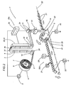
- 1 denotes a portion of an automatic packaging machine, in its entirety, in which a wrapping material 2 consisting in a single component C1, appearing as a continuous strip 9, is advanced along a feed path 3 extending from a decoiling roll 4 toward a user station 5.
- the roll 4 is mounted to a pivot 6 with a horizontally disposed axis 7, driven by a respective motor 8 such as will decoil the continuous strip 9 and cause it to advance through guiding and pulling devices 10, illustrated schematically and by way of example as an assembly of guides 11 and pinch rolls 12 arranged along the feed path 3, toward a cutter device 13 by which it is separated into discrete lengths, or sheets 14.
- guiding and pulling devices 10 illustrated schematically and by way of example as an assembly of guides 11 and pinch rolls 12 arranged along the feed path 3, toward a cutter device 13 by which it is separated into discrete lengths, or sheets 14.
- the sheets 14 are directed seriatim onto a take-up and feed unit 15 which in the example illustrated comprises a first roller 16 with a horizontally disposed axis 17 by which the sheets 14 are taken up and distanced one from another and from the strip 9, and a second roller 18, of which the axis 19 extends parallel to the first axis 17, operating in conjunction with the first roller 16 in such a way as to direct the sheets 14 along a vertical leg 20 of the feed path 3 toward the user station 5.
- a take-up and feed unit 15 which in the example illustrated comprises a first roller 16 with a horizontally disposed axis 17 by which the sheets 14 are taken up and distanced one from another and from the strip 9, and a second roller 18, of which the axis 19 extends parallel to the first axis 17, operating in conjunction with the first roller 16 in such a way as to direct the sheets 14 along a vertical leg 20 of the feed path 3 toward the user station 5.
- the single sheet 14 is intercepted at the user station 5 by a product 21 advancing along a second feed path 22 extending transversely to the vertical leg 20 of the first path 3.
- Each sheet 14 is united thus with a respective product 21, which it proceeds to envelop as the two are advanced along a wrapping line 23 that extends along the second feed path 22.
- the guiding and pulling devices 10 and the take-up and feed unit 15 together constitute means, denoted 24 in their entirety, by which to convey the wrapping material 2.
- a unit denoted 26a in its entirety for checking the wrapping material 2, of which a first embodiment is indicated in unbroken lines.
- the unit 26a comprises an electrostatic charge generator 28 of which the relative emitter device 29 is directed at the strip 9 in such a way that a predetermined portion 30 of the selfsame strip 9, advancing at a velocity denoted V1, is invested with a flow of electrostatic charges and thus charged electrostatically.
- the strip 9 is made of an electrically insulating material, or in any event the face of the strip offered to the emitter device 29 has electrically insulating properties.
- the unit 26a Located beyond the emitter device 29 in the downstream direction and in the area occupied by a second operative station 27b, at a given distance from the emitter device 29, the unit 26a comprises a sensor 31 capable of detecting electrostatic charges applied previously to the predetermined portions 30 of the strip 9.
- the checker unit 26a can also comprise discharger devices 32 which, in the embodiment of figure 1 illustrated with unbroken lines, comprise first and second sliding contacts 33 positioned respectively upstream of the emitter device 29 and downstream of the sensor 31.
- the two sliding contacts 33 are capable of movement between a position of no contact or disengagement relative to the strip 9, and a position of contact with the selfsame strip 9 (indicated in figure 1) in which they are able to rid the strip 9 of any leaked electrostatic charges and thus protect the strip 9, ensuring that such charges as may be attributable to leakage will not impact negatively on the checking function.
- the dischargers 32 in question can also be used to neutralize the strip 9 completely should it be expedient to suspend or terminate the checking function.
- the dischargers 32 in question might also be associated both with the guides 11 and with the rolls 12, in order to protect the strip 9 from electrostatic charges that may have leaked to the relative guiding and pulling device 10, and might consist in earth contacts 32a.
- a second embodiment illustrated with phantom lines in figure 1, includes a checker unit 26b positioned to coincide with the take-up and feed unit 15.
- the unit 26b comprises a respective electrostatic charge generator 28 of which the relative emitter device 29 is directed at the first roller 16 in such a way as to apply an electrostatic charge to a predetermined portion 34 of each successive sheet 14, also a respective sensor 31 positioned in alignment with the second roller 18 and capable of detecting electrostatic charges applied previously to the aforementioned predetermined portions 34.
- the two rollers 16 and 18 form part of conveying means 24 by which the wrapping material 2 is advanced along the feed path, and can be equipped similarly with respective discharger contacts 32a serving to connect the rollers 16 and 18 to earth.
- the continuous strip 9 is caused to advance at the predetermined velocity V1 and the emitter device 29 proceeds to charge the predetermined portions 30 electrostatically at a predetermined frequency, whilst the sensor 31 detects the charges thus applied to the strip 9.
- the operations of timing the delivery of charges from the emitter device 29 and measuring the signal received from the sensor 31 are governed by a master controller 35.
- the master controller 35 will relay a correction signal to the drive means 8 of the decoil roll 4 and/or to the pinch rolls 12 so that the feed rate will be re-established at the required value V1.
- the first roller 16 rotates on its axis 17 at a speed such as will cause the sheets 14 to be separated one from the next by a predetermined distance after being severed from the strip 9 by the cutter device 13, whilst the second roller 18 rotates at the same speed as the first roller 16.
- the relative master controller 35 will again govern the timing with which the sheets 14 are charged by the emitter 29 and measure the signal received from the sensor 31, which indicates both the presence of the sheets and their position relative to the moment at which the cut occurs.
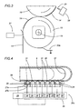
- the portion 1 of the packaging machine is structured in such a way that the continuous strip 9 decoiled from the respective roll 4 passes through a flow compensating chamber 36, illustrated in figure 4, internally of which the strip 9 forms a loop 37 expandable to a length that is variable within a predetermined range as indicated also in figure 2.
- the wrapping material 2 is checked by a unit 26c positioned along one longitudinal wall 38 of the chamber 36.
- the checker unit 26c comprises a plurality of emitter devices 29 arranged in succession along the longitudinal wall 38 of the flow compensating chamber 36, each positioned to charge a predetermined portion of the running strip 9 electrostatically, and a plurality of sensors 31 capable of detecting the electrostatic charges, arranged likewise in succession along the selfsame wall 38 of the chamber 36 and in alternation with the emitter devices 29.
- the emitter devices 29 arranged in succession along the longitudinal wall 38 of the flow compensating chamber 36 are positioned at respective first operative stations 27a, whilst the sensors 31 are positioned at respective second operative stations 27b.
- All of the emitters 29 are coupled to a common charge generator 28 connected to the output of the master controller 35.
- Each sensor 31 is wired to a respective control unit 39 forming part of the master controller 35. Also, each sensor 31 is associated with a respective emitter 29 in such a way that the presence of predetermined portions of the strip 9 within the flow compensating chamber 36 can be detected moment by moment, and any variation in the length of the loop 37 running through the selfsame chamber 36 thus monitored continuously.
- the master controller 35 will relay correction signals to the drive motor 8 of the roll 4 and/or to a set of pinch rolls 40 located at a point on the feed path 3 downstream of the flow compensating chamber 36.
- the strip 9 is guided along the feed path 3 by pinch rolls 40 and guide rollers 42 that perform the same functions as the pinch rolls 12 and the guides 11 illustrated in figure 1, combining thus to create means, denoted 24 in their entirety, by which the wrapping material 2 is conveyed toward the user station.
- dischargers 32 can be associated with the conveying means 24 to perform the same function as described in connection with the embodiments of figure 1.
- the checker units 26 are designed to operate upstream of the user station 5 and, accordingly, the steps of applying and detecting the electrostatic charges are effected along the feed path 3 followed by the wrapping material.
- a unit 26d comprising an emitter 29 and a sensor 31 located downstream of the user station 5 and on the second feed path 22, along which products 21 united with the wrapping material 2 at the user station 5 are caused to advance through the agency of a belt conveyor 41 constituting the aforementioned conveying means 24.
- dischargers 32 can be associated with the conveyor 41 for the purpose of eliminating any residual electrostatic charges from the conveying means 24.
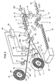
- the wrapping material 2 comprises a first component C1 provided by the continuous strip 9 decoiled from the roll 4, and a second component C2 appearing in this particular instance as a second strip 42 exhibiting a transverse dimension less than that of the first strip 9.
- the strip 42 is decoiled from a respective roll 43 mounted to a pivot 44 of which the axis 45 is disposed parallel to the axis 7 of the first roll 4, and driven by a respective motor (not illustrated) such as will cause the strip 42 to decoil at the same rate as the first strip 9.
- the strips 9 and 42 converge on a bonding station 46 at the start of the first feed path 3, which in this embodiment becomes a common path followed by the two components C1 and C2 bonded one to another.
- the station 46 comprises a pair of contrarotating rollers 47, disposed substantially tangential one to another with axes lying parallel to the axes 7 and 45 of the decoil rolls 4 and 43, and marking the start of the common feed path 3.
- the wrapping material 2 composed of the two strips 9 and 42 is directed and advanced toward the cutter device 13 through the agency of the guides 11 and the pinch rolls 12, respectively, and divided into sheets 14.
- the sheets 14 are conveyed one by one to the user station 5 where, as already described in referring to the embodiment of figure 1, they will be intercepted cyclically by the products 21 advancing along the second feed path 22 and conveyed together with the products along the wrapping line 23. Again, the pinch rolls 12 and the guides 11 can be furnished with earth contacts 32a.
- the legs 3a, 3b and 3 of the first feed path extending between the decoil rolls 4 and 43 and the pinch rolls 12 are occupied by a unit 48 for checking the wrapping material 2 that comprises, located on the leg 3a of the one strip 9, a discharger 32 with a relative sliding contact 33, and on the leg 3b of the other strip 42, proceeding from upstream downwards in the feed direction, a discharger 32 with a relative sliding contact 33 and, coinciding with a first operative station 49a, an electrostatic charge generator 28 with a respective emitter device 29 positioned to invest predetermined portions 30 of the strip 42 with electrostatic charges.
- the checker unit 48 Downstream of the bonding station 46, the checker unit 48 comprises a second operative station 49b equipped, as shown in figures 8 and 9, with one or more sensors 31 placed to detect the electrostatic charges applied at the first station 49a.
- the checker unit comprises a further sensor 31, positioned along the leg 3a of the wider strip 9 at a point between the discharger 32 and the bonding station 46, serving to detect any electrostatic charges present on this same strip 9.
- the checker unit 48 comprises a master controller 35 to which all of the various electrical and electronic components making up the unit are wired.
- the wrapping material 2 directed toward the cutter device 13 is no longer composed of two continuous strips bonded together, but rather of one continuous strip 9 as the first component C1 of the material and a succession of discrete lengths or slips 50 as the second component C2 of the material, with the strip 9 functioning as the support component.
- the slips 50 are cut and fixed to the strip 9 by a relative device of conventional type, indicated schematically by a block denoted 51, into which the first strip 9 is directed together with a second continuous strip 52, the latter passing through a respective cutter device 53.
- the strip 52 in the example of figure 6 is a continuous strip presenting the same transverse dimensions as the strip 42 of figure 5, and the slips 50 are applied to the strip 9 oriented parallel to the common feed path 3 followed by the wrapping material 2, maintaining a predetermined placement and a first longitudinal pitch denoted p1.
- the generator 28 and the corresponding emitter 29 can be positioned upstream of the cutter device 53 in such a way as to charge successive portions 30 of the continuous strip 52 destined to coincide substantially with the two ends of each slip 50 following the cutting operation.
- the generator 28 and the corresponding emitter 29 can be placed, as shown by the phantom lines, immediately downstream of the cutter device 53 and preceding the point at which the slips 50 are applied to the strip 9 at the bonding station 46, indicated schematically by a block, likewise in such a way as to charge the portions 30 coinciding with the ends of each slip 50.
- the strip 52 is a continuous strip of which the transverse dimension is broadly similar to that of the first strip 9, and the slips 50 are generated by a cutter device 53 set up so as divide the strip 52 into slivers, each constituting one slip 50.
- slips 50 are applied to the strip 9 at the bonding station 46, oriented transversely to the common feed path 3 followed by the wrapping material 3, maintaining a predetermined placement and a second longitudinal pitch denoted p2.
- the unit will need to incorporate two generators 28 with corresponding emitters 29 to enable the simultaneous application of electrostatic charges to the portions 30 coinciding with the ends of each slip 50.
- the two generators 28 can be placed upstream of the cutter device 53, aligned with the two opposite edges of the strip 52, or immediately downstream of the cutter device 53, as shown by the phantom lines, preceding the point at which the slips 50 are applied to the strip 9 and acting on the two ends of each sliver.
- the senor 31 placed at the second operative checking station 49b will be able, having successfully or unsuccessfully detected the charges applied previously at the first operative station 49a, to indicate the presence, the position, the timing and the orientation of the slips 50.
- the second operative checking station 49b is equipped with two sensors 31 which, having successfully or unsuccessfully detected the charges applied previously at the first operative station 49a, will be able to indicate the presence, the position, the timing and the orientation of the slips 50.
- the additional sensor 31 placed to detect the electrostatic charges can be set up to provide a differential type of control in combination with the second operative station 49b, to the end of avoiding any interference that may occur at this same station 49b due to the presence of residual charges on the strip 9; this method can also be adopted in the examples of figures 6 and 7.
- the master controller 35 is able to take account of any residual charges in the strip 9 that may be detected by the sensor 31 placed along the first leg 3a of the feed path.
- the generator 28 is able, through the agency of the corresponding emitter 29, to charge the predetermined portions 30 in pulsed mode at a selected frequency.
- the corresponding sensor 31 will be set up to detect and recognize the impulsive charges applied previously, thereby avoiding any interference that might otherwise be occasioned by residual charges on the strip 9.
- the sensors 31 can be installed in any convenient number, aligned transversely across or staggered along the common feed path 3. More exactly, these configurations will allow the checker unit to detect the presence and/or position of the strip 42 or the slips 50 within a band of predetermined width. Should it become evident from the detection step that the one strip 42 is advancing in an incorrect position relative to the other strip 9, the sensors will relay a control signal to a device of familiar type (not illustrated) capable of correcting the position of the decoiling strip 42, for example by shifting the roll 43 along its axis 45 of rotation.
- This type of marking is particularly advantageous for transparent wrapping materials, such as clear polypropylene, given that after the checking step has been effected, the mark can be removed simply by eliminating the charge from the wrapping material.
Landscapes
- Auxiliary Devices For And Details Of Packaging Control (AREA)
- Investigating Or Analyzing Materials By The Use Of Electric Means (AREA)
- Control Of Conveyors (AREA)
- Controlling Rewinding, Feeding, Winding, Or Abnormalities Of Webs (AREA)
- Containers And Plastic Fillers For Packaging (AREA)
- Basic Packing Technique (AREA)
- Replacement Of Web Rolls (AREA)
- Controlling Sheets Or Webs (AREA)
Claims (46)
- Un procédé de vérification de matériau d'emballage dans une machine à emballer, dans lequel le matériau d'emballage (2) est amené à la machine à emballer (1), caractérisé en ce qu'il comprend au moins les phases de chargement électrostatique d'au moins une partie prédéfinie (30, 34) du matériau d'emballage (2) en un point coïncidant avec au moins une première station de vérification (27a ; 49a), et de détection de la présence de charges électrostatiques sur la partie prédéfinie (30, 34) du matériau d'emballage (2) en un point coïncidant avec au moins une deuxième station de vérification (27b ; 49b).
- Le procédé selon la revendication 1, caractérisé en ce qu'il comprend une phase de protection du matériau d'emballage (2) contre d'éventuelles fuites des charges électrostatiques sur la partie prédéfinie (30, 34) du matériau (2).
- Le procédé selon la revendication 1 ou 2, caractérisé en ce que le matériau d'emballage (2) est destiné à envelopper des produits prédéfinis (21) au niveau d'une station utilisateur (5) et en ce que les phases d'application et de détection des charges électrostatiques sont exécutées le long d'un parcours d'alimentation (3) en amont de la station utilisateur (5).
- Le procédé selon la revendication 3, caractérisé en ce que le matériau d'emballage comprend au moins un élément d'emballage (C1, C2) et en ce que les phases d'application et de détection des charges électrostatiques sont exécutées sur une bande continue (9) de matériau d'emballage (2) définissant l'élément d'emballage (C1, C2) et avançant le long d'un parcours d'alimentation prédéfini (3a) correspondant.
- Le procédé selon la revendication 3, caractérisé en ce que le matériau d'emballage (2) comprend au moins un premier et un deuxième élément d'emballage (C1, C2) et en ce que les phases d'application et de détection des charges électrostatiques sont exécutées sur au moins un des deux éléments d'emballage (C1, C2).
- Le procédé selon la revendication 5, caractérisé en ce que les deux éléments d'emballage (C1, C2) consistent en deux bandes continues (9, 42) de matériau d'emballage, comprenant une phase de liaison des deux bandes (9, 42) l'une à l'autre dans des positions respectives prédéfinies.
- Le procédé selon la revendication 5, caractérisé en ce que le premier élément (C1) consiste en une bande continue (9) de matériau d'emballage et le deuxième élément (C2) consiste en une succession de longueurs données (50) de matériau d'emballage liées à la bande continue (9) à intervalles donnés (p1 ; p2) et dans une position prédéfinie.
- Le procédé selon la revendication 6 ou 7, caractérisé en ce qu'au moins la phase de détection est effectuée après la phase de liaison des deux éléments d'emballage (C1, C2) l'un à l'autre.
- Le procédé selon la revendication 6, caractérisé en ce que les deux bandes (9, 42) présentent des dimensions transversales différentes.
- Le procédé selon la revendication 7, caractérisé en ce que les longueurs données (50) de matériau d'emballage présentent une dimension transversale inférieure à celle de la bande continue (9).
- Le procédé selon la revendication 10, caractérisé en ce que les longueurs données (50) de matériau d'emballage sont liées à la bande continue (9) orientées parallèlement au parcours d'alimentation prédéfini (3) suivi par le matériau d'emballage (2).
- Le procédé selon la revendication 10, caractérisé en ce que les longueurs données (50) de matériau d'emballage sont liées à la bande continue (9) orientées transversalement au parcours d'alimentation prédéfini (3) suivi par le matériau d'emballage (2).
- Le procédé selon les revendications 11 et 12, caractérisé en ce que des charges électrostatiques sont appliquées à au moins deux parties distinctes (30) de chaque longueur donnée (50) de matériau d'emballage.
- Le procédé selon les revendications 5 à 13, caractérisé en ce que la phase de détection sert à vérifier la présence de l'élément (C1, C2) chargé au préalable.
- Le procédé selon la revendication 14, caractérisé en ce que la phase de détection sert à vérifier la position de l'élément (C1, C2) chargé au préalable.
- Le procédé selon la revendication 8, caractérisé en ce que la phase de détection sert à vérifier l'intervalle (p1 ; p2) auquel les longueurs données (50) sont espacées l'une de l'autre.
- Le procédé selon la revendication 13, caractérisé en ce que la phase de détection sert à vérifier l'intervalle (p1 ; p2) et l'orientation des longueurs données (50).
- Le procédé selon la revendication 6, caractérisé en ce que la phase d'application des charges électrostatiques est exécutée en mode pulsé à une fréquence prédéfinie.
- Le procédé selon la revendication 3, caractérisé en ce que les phases d'application et de détection des charges électrostatiques sont exécutées sur des longueurs données (14) de matériau d'emballage (2) obtenues par découpe d'un matériau continu (2) et avançant le long du parcours prédéfini (3).
- Le procédé selon la revendication 4, caractérisé en ce que le parcours d'alimentation (3a) suivi par le matériau d'emballage (2) s'étend à travers une chambre de compensation de mouvement (36), formant une boucle (37) de longueur variable dans une plage prédéfinie, et en ce que les phases d'application et de détection des charges électrostatiques sont exécutées le long de la plage prédéfinie déterminant la longueur de la boucle (37).
- Le procédé selon la revendication 20, comprenant une pluralité de phases d'application de charges électrostatiques et une pluralité de phases de détection de charges électrostatiques exécutées en alternance le long de la plage prédéfinie dans laquelle la longueur de la boucle (37) est variable.
- Le procédé selon la revendication 1 ou 2 ou 5, caractérisé en ce que le matériau d'emballage (2) est destiné à être uni avec des produits prédéfinis (21) au niveau d'une station utilisateur (5), et en ce que les phases d'application et de détection des charges électrostatiques sont exécutées en aval de la station utilisateur (5).
- Le procédé selon la revendication 22, caractérisé en ce que les produits (21) sont amenés vers la machine d'emballage (1) le long d'un deuxième parcours d'alimentation prédéfini (22) et unis avec le matériau d'emballage (2) et en ce que les phases d'application et de détection des charges électrostatiques sont exécutées le long du deuxième parcours prédéfini (22).
- Le procédé selon les revendications 1 à 23, comprenant au moins une phase d'élimination des charges électrostatiques du matériau d'emballage (2).
- Le procédé selon les revendications 1 à 24, caractérisé en ce que le matériau d'emballage (2) avance au moyen de moyens de transports (24) correspondants, comprenant au moins une phase d'élimination des charges électrostatiques des moyens de transport (24).
- Un dispositif de vérification de matériau d'emballage dans une machine à emballer, dans lequel le matériau d'emballage (2) est amené à la machine à emballer (1), caractérisé en ce qu'il comprend des moyens d'émission de charges électrostatiques (28, 29) à même de charger électrostatiquement au moins une partie prédéfinie (30, 34) du matériau d'emballage (2) en un point coïncidant avec au moins une première station de vérification (27a) et des moyens de détection (31) à même de détecter la présence de charges électrostatiques dans la partie prédéfinie (30, 34) du matériau d'emballage (2) en un point coïncidant avec au moins une deuxième station de vérification (27b).
- Le dispositif selon la revendication 26 de vérification de matériau d'emballage (2) consistant en au moins un élément d'emballage (C1 ; C2) sous forme d'une bande continue (9) avançant le long d'un parcours d'alimentation (3) correspondant, caractérisé en ce que les moyens d'émission (28, 29) sont placés le long du parcours d'alimentation (3) et en ce que les moyens de détection (31) sont placés le long dudit parcours d'alimentation (3) en aval et à une distance prédéfinie des moyens d'émission (28, 29) de façon à détecter la vitesse de la bande (9) qui avance.
- Le dispositif selon la revendication 27 de vérification de matériau d'emballage (2) composé d'un premier et d'un deuxième élément d'emballage (C1 ; C2), caractérisé en ce que les moyens d'émission (28, 29) et les moyens de détection (31) sont placés le long du parcours d'alimentation (3 ; 3a ; 3b) suivi par au moins un des deux éléments d'emballage (C1, C2).
- Le dispositif selon la revendication 28, caractérisé en ce que les deux éléments d'emballage consistent en deux bandes continues (9, 42) de matériau d'emballage, comprenant une station (46) au niveau de laquelle les deux bandes (9, 42) sont liées l'une à l'autre dans des positions respectives prédéfinies.
- Le dispositif selon la revendication 28, caractérisé en ce que le premier élément (C1) consiste en une bande continue (9) de matériau d'emballage et le deuxième élément (C2) consiste en une succession de longueurs données (50) de matériau d'emballage liées à la bande continue (9) à un intervalle prédéfini (p1 ; p2) et dans une position prédéfinie.
- Le dispositif selon la revendication 29 ou 30, caractérisé en ce qu'au moins les moyens de détection (31) sont placés en aval de la station (46) au niveau de laquelle les deux éléments d'emballage (C1, C2) sont liés l'un à l'autre.
- Le dispositif selon la revendication 29, caractérisé en ce que les deux bandes (9, 42) présentent des dimensions transversales différentes.
- Le dispositif selon la revendication 30, caractérisé en ce que les longueurs données (50) de matériau d'emballage présentent une dimension transversale inférieure à celle de la bande continue (9).
- Le dispositif selon la revendication 30, caractérisé en ce que les longueurs données (50) de matériau d'emballage sont liées à la bande continue (9) orientées parallèlement au parcours d'alimentation prédéfini (3) suivi par le matériau d'emballage (2).
- Le dispositif selon la revendication 30, caractérisé en ce que les longueurs données (50) de matériau d'emballage sont liées à la bande continue (9) orientées transversalement au parcours d'alimentation prédéfini (3) suivi par le matériau d'emballage (2).
- Le dispositif selon les revendications 34 et 35, caractérisé en ce que les moyens d'émission (28, 29) sont réalisés de façon à charger au moins deux parties distinctes (30) de chaque longueur donnée (50) de matériau d'emballage.
- Le dispositif selon les revendications 28 à 36, caractérisé en ce que les moyens de détection (31) comprennent des moyens (31) à même de vérifier la présence de l'élément (C1, C2) chargé au préalable.
- Le dispositif selon la revendication 37, caractérisé en ce que les moyens de détection (31) comprennent des moyens (31) à même de vérifier la position de l'élément (C1, C2) chargé au préalable.
- Le dispositif selon la revendication 31, caractérisé en ce que les moyens de détection (31) comprennent des moyens (31) à même de vérifier l'intervalle (p1 ; p2) auquel les longueurs données (50) sont espacées l'une de l'autre.
- Le dispositif selon la revendication 36, caractérisé en ce que les moyens de détection (31) comprennent des moyens (31) à même de vérifier l'intervalle (p1 ; p2) et l'orientation des longueurs données (50).
- Le dispositif selon la revendication 29, caractérisé en ce que les moyens d'émission (28, 29) comprennent un émetteur (29) délivrant des charges électrostatiques pulsées à une fréquence prédéfinie.
- Le dispositif selon la revendication 26 de vérification de matériau d'emballage (2) fourni sous forme de longueurs données (14) obtenues par découpe dudit matériau (2), caractérisé en ce que les moyens d'émission (28, 29) sont placés le long du parcours prédéfini (3) et en ce que les moyens de détection (31) sont placés le long dudit parcours (3) en aval et à une distance prédéfinie des moyens d'émission (28, 29), de façon à détecter la présence et/ou la synchronisation des longueurs données (14) de matériau d'emballage (2).
- Le dispositif selon la revendication 27 de vérification de matériau d'emballage (2) avançant le long d'un parcours d'alimentation (3), passant à travers une chambre de compensation de mouvement (36) et formant une boucle (37) de longueur variable dans une plage prédéfinie, caractérisé en ce que les moyens d'émission (28, 29) comprennent une pluralité de dispositifs émetteurs (29) agencés le long de la chambre de compensation de mouvement (36) et en ce que les moyens de détection (31) comprennent une pluralité de capteurs (31) à même de détecter les charges électrostatiques, agencés également le long de la chambre de compensation de mouvement (36) et alternés avec les dispositifs émetteurs (29) de façon à surveiller la variation de longueur de la boucle (37) à l'intérieur de la chambre (36).
- Le dispositif selon la revendication 26 de vérification de matériau d'emballage (2) destiné à être uni avec des produits prédéfinis (21) au niveau d'une station utilisateur (5), suite à quoi les produits (21) et le matériau (2) avancent le long d'un deuxième parcours d'alimentation prédéfini (22), caractérisé en ce que les moyens d'émission (28, 29) et les moyens de détection (31) sont placés le long du deuxième parcours prédéfini (22) de façon à vérifier la présence et/ou la vitesse et/ou la synchronisation des produits (21).
- Un dispositif selon les revendications 26 à 30, caractérisé en ce qu'il comprend des moyens de déchargement (32, 32a) placés en amont et/ou en aval des moyens d'émission (28, 29) et des moyens de détection (31) et servant à éliminer les charges électrostatiques du matériau d'emballage (2).
- Un dispositif selon les revendications 26 à 31, caractérisé en ce que le matériau d'emballage (2) avance au moyen de moyens de transport (24) correspondants, comprenant des moyens de déchargement (32, 32a) servant à éliminer les charges électrostatiques accumulées sur les moyens de transport (24).
Applications Claiming Priority (3)
| Application Number | Priority Date | Filing Date | Title |
|---|---|---|---|
| ITBO20010079 | 2001-02-14 | ||
| IT2001BO000079A ITBO20010079A1 (it) | 2001-02-14 | 2001-02-14 | Metodo e dispositivo per il controllo di materiale di incarto in una macchina confezionatrice |
| PCT/IB2001/002178 WO2002064470A1 (fr) | 2001-02-14 | 2001-11-19 | Procede et dispositif de verification du materiau d'emballage dans une machine a emballer |
Publications (2)
| Publication Number | Publication Date |
|---|---|
| EP1361996A1 EP1361996A1 (fr) | 2003-11-19 |
| EP1361996B1 true EP1361996B1 (fr) | 2006-10-25 |
Family
ID=11439095
Family Applications (1)
| Application Number | Title | Priority Date | Filing Date |
|---|---|---|---|
| EP01982658A Expired - Lifetime EP1361996B1 (fr) | 2001-02-14 | 2001-11-19 | Procede et dispositif de verification du materiau d'emballage dans une machine a emballer |
Country Status (8)
| Country | Link |
|---|---|
| US (1) | US7406809B2 (fr) |
| EP (1) | EP1361996B1 (fr) |
| JP (1) | JP2004518594A (fr) |
| CN (1) | CN1292969C (fr) |
| AT (1) | ATE343538T1 (fr) |
| DE (1) | DE60124145T2 (fr) |
| IT (1) | ITBO20010079A1 (fr) |
| WO (1) | WO2002064470A1 (fr) |
Cited By (1)
| Publication number | Priority date | Publication date | Assignee | Title |
|---|---|---|---|---|
| WO2023169941A1 (fr) | 2022-03-11 | 2023-09-14 | Focke & Co. (Gmbh & Co. Kg) | Dispositif et procédé de manipulation de découpes pour envelopper des articles d'emballage pour des produits de l'industrie des cigarettes |
Families Citing this family (5)
| Publication number | Priority date | Publication date | Assignee | Title |
|---|---|---|---|---|
| ITBO20020529A1 (it) | 2002-08-08 | 2004-02-09 | Gd Spa | Metodo per il controllo di materiale di incarto in |
| US8910689B2 (en) * | 2005-03-15 | 2014-12-16 | The Procter & Gamble Company | Apparatus for reducing downtime in web processes |
| US20070293382A1 (en) * | 2006-06-16 | 2007-12-20 | Cmd Corporation | Method and Apparatus for Making Bags |
| US20130091804A1 (en) * | 2011-08-08 | 2013-04-18 | Enfora, Inc. | Tape and reel orientation system |
| CN116507875A (zh) * | 2020-12-01 | 2023-07-28 | 利乐拉瓦尔集团及财务有限公司 | 一种检测和跟踪包装材料卷材特征的方法 |
Family Cites Families (14)
| Publication number | Priority date | Publication date | Assignee | Title |
|---|---|---|---|---|
| US3768227A (en) * | 1970-09-16 | 1973-10-30 | R Grisell | Method of dissipating static electricity in packaging |
| US3730753A (en) * | 1971-07-30 | 1973-05-01 | Eastman Kodak Co | Method for treating a web |
| CH553688A (de) * | 1972-07-03 | 1974-09-13 | Sig Schweiz Industrieges | Vorrichtung zum zufuehren von einschlagfolien an einer verpackungsmaschine. |
| US4590747A (en) * | 1984-05-11 | 1986-05-27 | Robert Alameda | Positive displacement filling machine |
| US5056646A (en) * | 1984-08-30 | 1991-10-15 | Polaroid Corporation | Electrostatic-type registration system |
| US4786353A (en) * | 1987-10-16 | 1988-11-22 | Adolph Coors Company | Laminating method and apparatus with extensible web width control |
| DE3822497A1 (de) | 1987-12-02 | 1989-10-19 | Kotterer Grafotec | Vorrichtung zum verhindern von maschinenschaeden |
| JPH02209284A (ja) * | 1989-02-10 | 1990-08-20 | Canon Inc | 記録装置の記録材検出装置 |
| US5444964A (en) * | 1993-06-22 | 1995-08-29 | Hanagata Corporation | Automatic package machine, and wrapping film fusing and sealing blade |
| JP3014576B2 (ja) | 1994-02-04 | 2000-02-28 | シャープ株式会社 | 記録媒体認識装置 |
| US5732529A (en) * | 1996-03-29 | 1998-03-31 | Ethicon, Inc. | Apparatus for feeding foil stock in a process for making sealed sterile packages |
| US6207925B1 (en) * | 1996-10-11 | 2001-03-27 | Brian Andrew Kendall | Apparatus for cutting and/or welding flexible packaging |
| US5873966A (en) * | 1997-10-14 | 1999-02-23 | Reliance Electric Industrial Company | Magnetic splice detection system |
| DE19825599A1 (de) * | 1998-06-09 | 1999-12-16 | Focke & Co | Verpackungsmaschine, insbesondere für Zigaretten |
-
2001
- 2001-02-14 IT IT2001BO000079A patent/ITBO20010079A1/it unknown
- 2001-11-19 AT AT01982658T patent/ATE343538T1/de not_active IP Right Cessation
- 2001-11-19 EP EP01982658A patent/EP1361996B1/fr not_active Expired - Lifetime
- 2001-11-19 DE DE60124145T patent/DE60124145T2/de not_active Expired - Fee Related
- 2001-11-19 WO PCT/IB2001/002178 patent/WO2002064470A1/fr not_active Ceased
- 2001-11-19 JP JP2002564410A patent/JP2004518594A/ja active Pending
- 2001-11-19 CN CNB01822587XA patent/CN1292969C/zh not_active Expired - Fee Related
- 2001-11-19 US US10/467,468 patent/US7406809B2/en not_active Expired - Fee Related
Cited By (1)
| Publication number | Priority date | Publication date | Assignee | Title |
|---|---|---|---|---|
| WO2023169941A1 (fr) | 2022-03-11 | 2023-09-14 | Focke & Co. (Gmbh & Co. Kg) | Dispositif et procédé de manipulation de découpes pour envelopper des articles d'emballage pour des produits de l'industrie des cigarettes |
Also Published As
| Publication number | Publication date |
|---|---|
| US7406809B2 (en) | 2008-08-05 |
| CN1489546A (zh) | 2004-04-14 |
| EP1361996A1 (fr) | 2003-11-19 |
| WO2002064470A1 (fr) | 2002-08-22 |
| DE60124145T2 (de) | 2007-09-06 |
| JP2004518594A (ja) | 2004-06-24 |
| US20040072664A1 (en) | 2004-04-15 |
| ATE343538T1 (de) | 2006-11-15 |
| ITBO20010079A0 (it) | 2001-02-14 |
| DE60124145D1 (de) | 2006-12-07 |
| CN1292969C (zh) | 2007-01-03 |
| ITBO20010079A1 (it) | 2002-08-14 |
Similar Documents
| Publication | Publication Date | Title |
|---|---|---|
| JP3073001B2 (ja) | ラベル貼り機のためのオンラインエンボス装置 | |
| US4757930A (en) | Web indicia reference signal generating system | |
| EP0061788B1 (fr) | Procédé et appareil pour raccorder des bandes de matériau d'emballage | |
| US4682038A (en) | Arrangement for monitoring and controlling webs in packaging machines | |
| US6508173B1 (en) | Process and apparatus for printing blanks | |
| PL199487B1 (pl) | Sposób i urządzenie do doprowadzania perforowanej odcinkami wstęgi bibułki na osłonki do wentylowanych papierosów | |
| EP1361996B1 (fr) | Procede et dispositif de verification du materiau d'emballage dans une machine a emballer | |
| US6886310B1 (en) | Device and method for making packaging bags | |
| EP0084299A1 (fr) | Système pour régler l'alimentation d'articles vers une machine d'emballage | |
| US6603887B1 (en) | Process and apparatus for detecting printed marks | |
| ITBO980204A1 (it) | Apparato per la formatura di un involucro in carta termosaldabile per confezionamento di un prodotto. | |
| JP4249564B2 (ja) | ラッピング材をパッケージング機において検査する方法 | |
| JPS62228264A (ja) | 2本どり紙巻たばこ棒製造機械における帯状用紙供給装置 | |
| US20220219930A1 (en) | Feeding unit for feeding a plastic film | |
| EP0237299B1 (fr) | Appareil d'alimentation | |
| US4086846A (en) | Apparatus and method to sense and adjust the relative position of hollow tubes within a continuous filter | |
| EP0787651A1 (fr) | Procédé pour alimenter des feuilles de matériau d'enveloppement | |
| KR100548755B1 (ko) | 겉포장기 | |
| US5823528A (en) | Device for feeding blanks on a cigarette packing machine | |
| EP0761547B1 (fr) | Dispositif et procédé pour vérifier l'intégrité d'emballages de produits dans une machine d'emballage | |
| JP2004010107A (ja) | 連続包装体の搬送位置検出方法および搬送位置検出装置 | |
| GB2247952A (en) | Apparatus for conveying a flat article | |
| US20040177912A1 (en) | Corrugating machine with multiple thermal position sensing | |
| EP4074491B1 (fr) | Machine pour la fabrication de sachets de matière sans cohésion et méthode associée | |
| JPH07285715A (ja) | 製袋充填包装機における原反送出し方法及び装置 |
Legal Events
| Date | Code | Title | Description |
|---|---|---|---|
| PUAI | Public reference made under article 153(3) epc to a published international application that has entered the european phase |
Free format text: ORIGINAL CODE: 0009012 |
|
| 17P | Request for examination filed |
Effective date: 20030903 |
|
| AK | Designated contracting states |
Kind code of ref document: A1 Designated state(s): AT BE CH CY DE DK ES FI FR GB GR IE IT LI LU MC NL PT SE TR |
|
| AX | Request for extension of the european patent |
Extension state: AL LT LV MK RO SI |
|
| GRAP | Despatch of communication of intention to grant a patent |
Free format text: ORIGINAL CODE: EPIDOSNIGR1 |
|
| GRAS | Grant fee paid |
Free format text: ORIGINAL CODE: EPIDOSNIGR3 |
|
| GRAA | (expected) grant |
Free format text: ORIGINAL CODE: 0009210 |
|
| AK | Designated contracting states |
Kind code of ref document: B1 Designated state(s): AT BE CH CY DE DK ES FI FR GB GR IE IT LI LU MC NL PT SE TR |
|
| PG25 | Lapsed in a contracting state [announced via postgrant information from national office to epo] |
Ref country code: IT Free format text: LAPSE BECAUSE OF FAILURE TO SUBMIT A TRANSLATION OF THE DESCRIPTION OR TO PAY THE FEE WITHIN THE PRESCRIBED TIME-LIMIT;WARNING: LAPSES OF ITALIAN PATENTS WITH EFFECTIVE DATE BEFORE 2007 MAY HAVE OCCURRED AT ANY TIME BEFORE 2007. THE CORRECT EFFECTIVE DATE MAY BE DIFFERENT FROM THE ONE RECORDED. Effective date: 20061025 Ref country code: AT Free format text: LAPSE BECAUSE OF FAILURE TO SUBMIT A TRANSLATION OF THE DESCRIPTION OR TO PAY THE FEE WITHIN THE PRESCRIBED TIME-LIMIT Effective date: 20061025 Ref country code: BE Free format text: LAPSE BECAUSE OF FAILURE TO SUBMIT A TRANSLATION OF THE DESCRIPTION OR TO PAY THE FEE WITHIN THE PRESCRIBED TIME-LIMIT Effective date: 20061025 Ref country code: NL Free format text: LAPSE BECAUSE OF FAILURE TO SUBMIT A TRANSLATION OF THE DESCRIPTION OR TO PAY THE FEE WITHIN THE PRESCRIBED TIME-LIMIT Effective date: 20061025 Ref country code: FI Free format text: LAPSE BECAUSE OF FAILURE TO SUBMIT A TRANSLATION OF THE DESCRIPTION OR TO PAY THE FEE WITHIN THE PRESCRIBED TIME-LIMIT Effective date: 20061025 |
|
| REG | Reference to a national code |
Ref country code: GB Ref legal event code: FG4D |
|
| REG | Reference to a national code |
Ref country code: CH Ref legal event code: EP |
|
| PGFP | Annual fee paid to national office [announced via postgrant information from national office to epo] |
Ref country code: FR Payment date: 20061117 Year of fee payment: 6 |
|
| PG25 | Lapsed in a contracting state [announced via postgrant information from national office to epo] |
Ref country code: IE Free format text: LAPSE BECAUSE OF NON-PAYMENT OF DUE FEES Effective date: 20061120 |
|
| PGFP | Annual fee paid to national office [announced via postgrant information from national office to epo] |
Ref country code: GB Payment date: 20061122 Year of fee payment: 6 |
|
| PGFP | Annual fee paid to national office [announced via postgrant information from national office to epo] |
Ref country code: CH Payment date: 20061124 Year of fee payment: 6 |
|
| REG | Reference to a national code |
Ref country code: IE Ref legal event code: FG4D |
|
| PG25 | Lapsed in a contracting state [announced via postgrant information from national office to epo] |
Ref country code: MC Free format text: LAPSE BECAUSE OF NON-PAYMENT OF DUE FEES Effective date: 20061130 |
|
| REF | Corresponds to: |
Ref document number: 60124145 Country of ref document: DE Date of ref document: 20061207 Kind code of ref document: P |
|
| PGFP | Annual fee paid to national office [announced via postgrant information from national office to epo] |
Ref country code: DE Payment date: 20070102 Year of fee payment: 6 |
|
| PG25 | Lapsed in a contracting state [announced via postgrant information from national office to epo] |
Ref country code: SE Free format text: LAPSE BECAUSE OF FAILURE TO SUBMIT A TRANSLATION OF THE DESCRIPTION OR TO PAY THE FEE WITHIN THE PRESCRIBED TIME-LIMIT Effective date: 20070125 Ref country code: DK Free format text: LAPSE BECAUSE OF FAILURE TO SUBMIT A TRANSLATION OF THE DESCRIPTION OR TO PAY THE FEE WITHIN THE PRESCRIBED TIME-LIMIT Effective date: 20070125 |
|
| PG25 | Lapsed in a contracting state [announced via postgrant information from national office to epo] |
Ref country code: ES Free format text: LAPSE BECAUSE OF FAILURE TO SUBMIT A TRANSLATION OF THE DESCRIPTION OR TO PAY THE FEE WITHIN THE PRESCRIBED TIME-LIMIT Effective date: 20070205 |
|
| PG25 | Lapsed in a contracting state [announced via postgrant information from national office to epo] |
Ref country code: PT Free format text: LAPSE BECAUSE OF FAILURE TO SUBMIT A TRANSLATION OF THE DESCRIPTION OR TO PAY THE FEE WITHIN THE PRESCRIBED TIME-LIMIT Effective date: 20070326 |
|
| NLV1 | Nl: lapsed or annulled due to failure to fulfill the requirements of art. 29p and 29m of the patents act | ||
| ET | Fr: translation filed | ||
| PLBE | No opposition filed within time limit |
Free format text: ORIGINAL CODE: 0009261 |
|
| STAA | Information on the status of an ep patent application or granted ep patent |
Free format text: STATUS: NO OPPOSITION FILED WITHIN TIME LIMIT |
|
| 26N | No opposition filed |
Effective date: 20070726 |
|
| PG25 | Lapsed in a contracting state [announced via postgrant information from national office to epo] |
Ref country code: GR Free format text: LAPSE BECAUSE OF FAILURE TO SUBMIT A TRANSLATION OF THE DESCRIPTION OR TO PAY THE FEE WITHIN THE PRESCRIBED TIME-LIMIT Effective date: 20070126 |
|
| GBPC | Gb: european patent ceased through non-payment of renewal fee |
Effective date: 20071119 |
|
| PG25 | Lapsed in a contracting state [announced via postgrant information from national office to epo] |
Ref country code: TR Free format text: LAPSE BECAUSE OF FAILURE TO SUBMIT A TRANSLATION OF THE DESCRIPTION OR TO PAY THE FEE WITHIN THE PRESCRIBED TIME-LIMIT Effective date: 20061025 Ref country code: LU Free format text: LAPSE BECAUSE OF NON-PAYMENT OF DUE FEES Effective date: 20061119 Ref country code: LI Free format text: LAPSE BECAUSE OF NON-PAYMENT OF DUE FEES Effective date: 20071130 Ref country code: CH Free format text: LAPSE BECAUSE OF NON-PAYMENT OF DUE FEES Effective date: 20071130 |
|
| REG | Reference to a national code |
Ref country code: CH Ref legal event code: PL |
|
| PG25 | Lapsed in a contracting state [announced via postgrant information from national office to epo] |
Ref country code: DE Free format text: LAPSE BECAUSE OF NON-PAYMENT OF DUE FEES Effective date: 20080603 |
|
| REG | Reference to a national code |
Ref country code: FR Ref legal event code: ST Effective date: 20080930 |
|
| PG25 | Lapsed in a contracting state [announced via postgrant information from national office to epo] |
Ref country code: CY Free format text: LAPSE BECAUSE OF FAILURE TO SUBMIT A TRANSLATION OF THE DESCRIPTION OR TO PAY THE FEE WITHIN THE PRESCRIBED TIME-LIMIT Effective date: 20061025 |
|
| PG25 | Lapsed in a contracting state [announced via postgrant information from national office to epo] |
Ref country code: GB Free format text: LAPSE BECAUSE OF NON-PAYMENT OF DUE FEES Effective date: 20071119 |
|
| PG25 | Lapsed in a contracting state [announced via postgrant information from national office to epo] |
Ref country code: FR Free format text: LAPSE BECAUSE OF NON-PAYMENT OF DUE FEES Effective date: 20071130 |