EP1361621B1 - Verfahren zum Betreiben einer Brennstoffzellenanlage - Google Patents
Verfahren zum Betreiben einer Brennstoffzellenanlage Download PDFInfo
- Publication number
- EP1361621B1 EP1361621B1 EP03009657.2A EP03009657A EP1361621B1 EP 1361621 B1 EP1361621 B1 EP 1361621B1 EP 03009657 A EP03009657 A EP 03009657A EP 1361621 B1 EP1361621 B1 EP 1361621B1
- Authority
- EP
- European Patent Office
- Prior art keywords
- fuel cell
- voltage
- electrical
- hydrogen
- thermal energy
- Prior art date
- Legal status (The legal status is an assumption and is not a legal conclusion. Google has not performed a legal analysis and makes no representation as to the accuracy of the status listed.)
- Expired - Lifetime
Links
Images

Classifications
-
- C—CHEMISTRY; METALLURGY
- C01—INORGANIC CHEMISTRY
- C01B—NON-METALLIC ELEMENTS; COMPOUNDS THEREOF; METALLOIDS OR COMPOUNDS THEREOF NOT COVERED BY SUBCLASS C01C
- C01B3/00—Hydrogen; Gaseous mixtures containing hydrogen; Separation of hydrogen from mixtures containing it; Purification of hydrogen; Reversible storage of hydrogen
- C01B3/02—Production of hydrogen; Production of gaseous mixtures containing hydrogen
- C01B3/32—Production of hydrogen; Production of gaseous mixtures containing hydrogen by reaction of gaseous or liquid organic compounds with gasifying agents, e.g. water, carbon dioxide or air
- C01B3/34—Production of hydrogen; Production of gaseous mixtures containing hydrogen by reaction of gaseous or liquid organic compounds with gasifying agents, e.g. water, carbon dioxide or air by reaction of hydrocarbons with gasifying agents
- C01B3/38—Production of hydrogen; Production of gaseous mixtures containing hydrogen by reaction of gaseous or liquid organic compounds with gasifying agents, e.g. water, carbon dioxide or air by reaction of hydrocarbons with gasifying agents using catalysts
-
- H—ELECTRICITY
- H01—ELECTRIC ELEMENTS
- H01M—PROCESSES OR MEANS, e.g. BATTERIES, FOR THE DIRECT CONVERSION OF CHEMICAL ENERGY INTO ELECTRICAL ENERGY
- H01M8/00—Fuel cells; Manufacture thereof
- H01M8/04—Auxiliary arrangements, e.g. for control of pressure or for circulation of fluids
- H01M8/04298—Processes for controlling fuel cells or fuel cell systems
- H01M8/04313—Processes for controlling fuel cells or fuel cell systems characterised by the detection or assessment of variables; characterised by the detection or assessment of failure or abnormal function
- H01M8/04537—Electric variables
- H01M8/04544—Voltage
- H01M8/04559—Voltage of fuel cell stacks
-
- H—ELECTRICITY
- H01—ELECTRIC ELEMENTS
- H01M—PROCESSES OR MEANS, e.g. BATTERIES, FOR THE DIRECT CONVERSION OF CHEMICAL ENERGY INTO ELECTRICAL ENERGY
- H01M8/00—Fuel cells; Manufacture thereof
- H01M8/04—Auxiliary arrangements, e.g. for control of pressure or for circulation of fluids
- H01M8/04298—Processes for controlling fuel cells or fuel cell systems
- H01M8/04313—Processes for controlling fuel cells or fuel cell systems characterised by the detection or assessment of variables; characterised by the detection or assessment of failure or abnormal function
- H01M8/04537—Electric variables
- H01M8/04604—Power, energy, capacity or load
- H01M8/04619—Power, energy, capacity or load of fuel cell stacks
-
- H—ELECTRICITY
- H01—ELECTRIC ELEMENTS
- H01M—PROCESSES OR MEANS, e.g. BATTERIES, FOR THE DIRECT CONVERSION OF CHEMICAL ENERGY INTO ELECTRICAL ENERGY
- H01M8/00—Fuel cells; Manufacture thereof
- H01M8/04—Auxiliary arrangements, e.g. for control of pressure or for circulation of fluids
- H01M8/04298—Processes for controlling fuel cells or fuel cell systems
- H01M8/04694—Processes for controlling fuel cells or fuel cell systems characterised by variables to be controlled
- H01M8/04701—Temperature
- H01M8/04731—Temperature of other components of a fuel cell or fuel cell stacks
-
- H—ELECTRICITY
- H01—ELECTRIC ELEMENTS
- H01M—PROCESSES OR MEANS, e.g. BATTERIES, FOR THE DIRECT CONVERSION OF CHEMICAL ENERGY INTO ELECTRICAL ENERGY
- H01M8/00—Fuel cells; Manufacture thereof
- H01M8/04—Auxiliary arrangements, e.g. for control of pressure or for circulation of fluids
- H01M8/04298—Processes for controlling fuel cells or fuel cell systems
- H01M8/04694—Processes for controlling fuel cells or fuel cell systems characterised by variables to be controlled
- H01M8/04746—Pressure; Flow
- H01M8/04753—Pressure; Flow of fuel cell reactants
-
- H—ELECTRICITY
- H01—ELECTRIC ELEMENTS
- H01M—PROCESSES OR MEANS, e.g. BATTERIES, FOR THE DIRECT CONVERSION OF CHEMICAL ENERGY INTO ELECTRICAL ENERGY
- H01M8/00—Fuel cells; Manufacture thereof
- H01M8/04—Auxiliary arrangements, e.g. for control of pressure or for circulation of fluids
- H01M8/04298—Processes for controlling fuel cells or fuel cell systems
- H01M8/04694—Processes for controlling fuel cells or fuel cell systems characterised by variables to be controlled
- H01M8/04746—Pressure; Flow
- H01M8/04776—Pressure; Flow at auxiliary devices, e.g. reformer, compressor, burner
-
- H—ELECTRICITY
- H01—ELECTRIC ELEMENTS
- H01M—PROCESSES OR MEANS, e.g. BATTERIES, FOR THE DIRECT CONVERSION OF CHEMICAL ENERGY INTO ELECTRICAL ENERGY
- H01M8/00—Fuel cells; Manufacture thereof
- H01M8/04—Auxiliary arrangements, e.g. for control of pressure or for circulation of fluids
- H01M8/04298—Processes for controlling fuel cells or fuel cell systems
- H01M8/04694—Processes for controlling fuel cells or fuel cell systems characterised by variables to be controlled
- H01M8/04858—Electric variables
- H01M8/04865—Voltage
- H01M8/0488—Voltage of fuel cell stacks
-
- H—ELECTRICITY
- H01—ELECTRIC ELEMENTS
- H01M—PROCESSES OR MEANS, e.g. BATTERIES, FOR THE DIRECT CONVERSION OF CHEMICAL ENERGY INTO ELECTRICAL ENERGY
- H01M8/00—Fuel cells; Manufacture thereof
- H01M8/04—Auxiliary arrangements, e.g. for control of pressure or for circulation of fluids
- H01M8/04298—Processes for controlling fuel cells or fuel cell systems
- H01M8/04694—Processes for controlling fuel cells or fuel cell systems characterised by variables to be controlled
- H01M8/04858—Electric variables
- H01M8/04895—Current
- H01M8/0491—Current of fuel cell stacks
-
- H—ELECTRICITY
- H01—ELECTRIC ELEMENTS
- H01M—PROCESSES OR MEANS, e.g. BATTERIES, FOR THE DIRECT CONVERSION OF CHEMICAL ENERGY INTO ELECTRICAL ENERGY
- H01M8/00—Fuel cells; Manufacture thereof
- H01M8/06—Combination of fuel cells with means for production of reactants or for treatment of residues
- H01M8/0606—Combination of fuel cells with means for production of reactants or for treatment of residues with means for production of gaseous reactants
- H01M8/0612—Combination of fuel cells with means for production of reactants or for treatment of residues with means for production of gaseous reactants from carbon-containing material
-
- C—CHEMISTRY; METALLURGY
- C01—INORGANIC CHEMISTRY
- C01B—NON-METALLIC ELEMENTS; COMPOUNDS THEREOF; METALLOIDS OR COMPOUNDS THEREOF NOT COVERED BY SUBCLASS C01C
- C01B2203/00—Integrated processes for the production of hydrogen or synthesis gas
- C01B2203/02—Processes for making hydrogen or synthesis gas
- C01B2203/0205—Processes for making hydrogen or synthesis gas containing a reforming step
- C01B2203/0227—Processes for making hydrogen or synthesis gas containing a reforming step containing a catalytic reforming step
-
- C—CHEMISTRY; METALLURGY
- C01—INORGANIC CHEMISTRY
- C01B—NON-METALLIC ELEMENTS; COMPOUNDS THEREOF; METALLOIDS OR COMPOUNDS THEREOF NOT COVERED BY SUBCLASS C01C
- C01B2203/00—Integrated processes for the production of hydrogen or synthesis gas
- C01B2203/04—Integrated processes for the production of hydrogen or synthesis gas containing a purification step for the hydrogen or the synthesis gas
- C01B2203/0435—Catalytic purification
- C01B2203/044—Selective oxidation of carbon monoxide
-
- C—CHEMISTRY; METALLURGY
- C01—INORGANIC CHEMISTRY
- C01B—NON-METALLIC ELEMENTS; COMPOUNDS THEREOF; METALLOIDS OR COMPOUNDS THEREOF NOT COVERED BY SUBCLASS C01C
- C01B2203/00—Integrated processes for the production of hydrogen or synthesis gas
- C01B2203/04—Integrated processes for the production of hydrogen or synthesis gas containing a purification step for the hydrogen or the synthesis gas
- C01B2203/0465—Composition of the impurity
- C01B2203/047—Composition of the impurity the impurity being carbon monoxide
-
- C—CHEMISTRY; METALLURGY
- C01—INORGANIC CHEMISTRY
- C01B—NON-METALLIC ELEMENTS; COMPOUNDS THEREOF; METALLOIDS OR COMPOUNDS THEREOF NOT COVERED BY SUBCLASS C01C
- C01B2203/00—Integrated processes for the production of hydrogen or synthesis gas
- C01B2203/06—Integration with other chemical processes
- C01B2203/066—Integration with other chemical processes with fuel cells
-
- H—ELECTRICITY
- H01—ELECTRIC ELEMENTS
- H01M—PROCESSES OR MEANS, e.g. BATTERIES, FOR THE DIRECT CONVERSION OF CHEMICAL ENERGY INTO ELECTRICAL ENERGY
- H01M8/00—Fuel cells; Manufacture thereof
- H01M8/10—Fuel cells with solid electrolytes
- H01M2008/1095—Fuel cells with polymeric electrolytes
-
- H—ELECTRICITY
- H01—ELECTRIC ELEMENTS
- H01M—PROCESSES OR MEANS, e.g. BATTERIES, FOR THE DIRECT CONVERSION OF CHEMICAL ENERGY INTO ELECTRICAL ENERGY
- H01M2250/00—Fuel cells for particular applications; Specific features of fuel cell system
- H01M2250/40—Combination of fuel cells with other energy production systems
- H01M2250/405—Cogeneration of heat or hot water
-
- H—ELECTRICITY
- H01—ELECTRIC ELEMENTS
- H01M—PROCESSES OR MEANS, e.g. BATTERIES, FOR THE DIRECT CONVERSION OF CHEMICAL ENERGY INTO ELECTRICAL ENERGY
- H01M8/00—Fuel cells; Manufacture thereof
- H01M8/04—Auxiliary arrangements, e.g. for control of pressure or for circulation of fluids
- H01M8/04007—Auxiliary arrangements, e.g. for control of pressure or for circulation of fluids related to heat exchange
- H01M8/04014—Heat exchange using gaseous fluids; Heat exchange by combustion of reactants
- H01M8/04022—Heating by combustion
-
- Y—GENERAL TAGGING OF NEW TECHNOLOGICAL DEVELOPMENTS; GENERAL TAGGING OF CROSS-SECTIONAL TECHNOLOGIES SPANNING OVER SEVERAL SECTIONS OF THE IPC; TECHNICAL SUBJECTS COVERED BY FORMER USPC CROSS-REFERENCE ART COLLECTIONS [XRACs] AND DIGESTS
- Y02—TECHNOLOGIES OR APPLICATIONS FOR MITIGATION OR ADAPTATION AGAINST CLIMATE CHANGE
- Y02B—CLIMATE CHANGE MITIGATION TECHNOLOGIES RELATED TO BUILDINGS, e.g. HOUSING, HOUSE APPLIANCES OR RELATED END-USER APPLICATIONS
- Y02B90/00—Enabling technologies or technologies with a potential or indirect contribution to GHG emissions mitigation
- Y02B90/10—Applications of fuel cells in buildings
-
- Y—GENERAL TAGGING OF NEW TECHNOLOGICAL DEVELOPMENTS; GENERAL TAGGING OF CROSS-SECTIONAL TECHNOLOGIES SPANNING OVER SEVERAL SECTIONS OF THE IPC; TECHNICAL SUBJECTS COVERED BY FORMER USPC CROSS-REFERENCE ART COLLECTIONS [XRACs] AND DIGESTS
- Y02—TECHNOLOGIES OR APPLICATIONS FOR MITIGATION OR ADAPTATION AGAINST CLIMATE CHANGE
- Y02E—REDUCTION OF GREENHOUSE GAS [GHG] EMISSIONS, RELATED TO ENERGY GENERATION, TRANSMISSION OR DISTRIBUTION
- Y02E60/00—Enabling technologies; Technologies with a potential or indirect contribution to GHG emissions mitigation
- Y02E60/30—Hydrogen technology
- Y02E60/50—Fuel cells
Definitions
- the invention relates to a method for operating a fuel cell system.
- a fuel gas - usually a hydrogen-containing gas - is oxidized by means of an electrochemical reaction. This reaction produces electrical power and heat.
- Hydrogen is a secondary energy source that must be produced from other sources of energy. Very often reformers are used for this purpose, which produce a hydrogen-rich process gas from hydrocarbons.
- a platinum catalytically coated anode is supplied with hydrogen-rich gas.
- the molecular hydrogen (H 2 ) is split on the catalyst into atomic hydrogen (H).
- the hydrogen atoms send their electrons (e - ) via an interconnector to an electrical circuit, whereby the remaining hydrogen nuclei (H + ) consist only of pure protons.
- the protons can pass through an electrolyte membrane, which is impermeable to other particles, to the cathode side of the fuel cell.
- an electrolyte membrane which is impermeable to other particles, to the cathode side of the fuel cell.
- molecular oxygen in the air is converted into oxygen ions (O 2- ) with the addition of electrons from the circuit. These react with the protons to form water vapor.
- the released energy of 242 kJ / mol is about half converted into electrical power and heat.
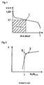
- the cell voltage is load-dependent. At idling, it is theoretically 1,228 V and falls with a load with simultaneous increase of the current (see. Fig. 1 ). The current, in turn, is dependent on the membrane area and load, given sufficient hydrogen supply.
- PEM fuel cells are operated at approximately 0.7 volts. Several fuel cells are connected in series to a fuel cell stack to obtain a voltage that can be efficiently processed.
- the hydrocarbons (C n H m ) can be partially oxidized exothermically with oxygen (O 2 ) or steam-reformed endothermically with steam (H 2 O). Both reactions produce carbon dioxide (CO 2 ) and hydrogen (H 2 ).
- Reformers are operated in such a way that as little hydrogen as possible reacts with oxygen. This leaves a relatively high concentration of carbon monoxide in the process gas. This is oxidized in a selective oxidizer with oxygen to carbon dioxide. 2CO + O 2 ⁇ 2CO 2
- Natural sulfur in the process gas must be avoided. Natural sulfur is scarcely present in natural gas; however, sulfur compounds are usually added to the gas as the odorizing agent. The most common is tetrahydrothiophene (THT, C 4 H 8 S). To remove the sulfur from the natural gas, zinc oxide or activated carbon filters can be used.
- the complex reforming process should be operated as steadily as possible.
- the start process may take several hours, requires energy for heating the reformer in this time and leads to aging of the catalysts.
- fuel cell systems with reformer are therefore operated modulatively with long maturities.
- Decentralized fuel cell systems of low power are usually operated by heat. The heat is then used for hot water and heating and the electricity is fed into an electrical grid.
- the fuel cell system is usually not designed for the thermal peak load of one or more consumers and heat - especially in the summer - not is required, usually a hot water tank is integrated into the overall system. This makes it possible to operate the system continuously with only a small modulation speed, which is advantageous for the reformer, since this can not respond quickly to load changes due to its thermal inertia.
- the object of the invention is therefore to operate a fuel cell system such that at each operating point, in particular during load changes, the efficiency is optimal and at the same time damage to the fuel cell is avoided.
- results according to the features of claim 3 mainly an advantage if the fuel cell system is mainly used as a power generator and the heat covers only part of the required heat demand, so anyway a second heat unit is used.
- the features of claim 4 take into account the fact that the extracted electrical power (current times voltage) can be changed by varying the voltage with known current-voltage characteristic.
- the fuel cell is operated with optimum hydrogen utilization.
- Fig. 1 is a characteristic course of a current-voltage characteristic can be seen.
- the theoretical cell voltage is 1.228 V and drops as the load increases.
- the power results from the product of current and voltage and is at about 0.7 V maximum.
- the point I should represent the setpoint.
- Fig. 2 shows the relationship between the hydrogen stoichiometry and the cell voltage.
- hydrogen stoichiometry the ratio between the supplied hydrogen flow ⁇ H2 and the stoichiometrically required hydrogen ⁇ H2 , stoichiometrically referred to the theoretical satisfaction of the desired power.
- a fuel cell needs a certain excess of hydrogen; If this is exceeded, the cell voltage is almost constant. If the hydrogen stoichiometry falls below this minimum excess, the cell voltage breaks down; this point is labeled II in the diagram. If the hydrogen stoichiometry is significantly smaller than this limiting stoichiometry, the voltage breaks down considerably and the membrane of the fuel cell is damaged.
- a fuel cell system with reformer for the production of hydrogen-rich process gas from natural gas is shown simplified.
- a natural gas connection 10 is connected to a sulfur filter 4 and upstream with a controllable compressor 6 for pressure increase, to be subsequently fed to a reformer 2.
- the reformer 2 also passes water vapor via a controllable pump 8 and atmospheric oxygen via a variable-speed compressor 7.
- the reformer 2 is connected via a connecting line 9 with a fuel cell stack 1 on the anode side.
- a compressor 11 On the cathode side of the fuel cell stack 1, a compressor 11, which is connected on its suction side with ambient air, connected.
- the gas exits of the fuel cell stack 1 are connected to a kathalytic afterburner 12. From this leads a line to an exhaust gas heat exchanger 13.
- a cooling circuit 14 has a heat exchanger 15 in the fuel cell stack 1, a heat exchanger 16 in the exhaust gas heat exchanger 13, a thermal consumer 17 with temperature sensor 19 and a circulation pump 18.
- the fuel cell stack 1 is further provided with an inverter 20th and a voltmeter 21.
- the compressors 6, 7, 11, the circulation pump 8, the temperature sensor 19, the inverter 20 and the voltmeter 21 are connected to the controller 5.
- the resulting carbon monoxide is oxidized in a second stage with atmospheric oxygen to carbon dioxide.
- the reformate is moistened and flows via a connecting line 9 to the anodes of the individual fuel cells.
- humidified air is supplied to the cathode side of the fuel cell stack 1.
- Hydrogen and oxygen react electrochemically in the fuel cell stack 1, producing electrical energy and heat.
- An inverter 20 converts the DC voltage generated in the fuel cell stack 1 into 230 V AC (50 Hz) AC power. A portion of the heat released is on the heat exchanger 15 to the Transfer cooling circuit 14.
- the fuel cell stack 1 Since the fuel cell stack 1 does not convert all of the fuel gas supplied to it, the combustible constituents of the exhaust gas are burned in a catalytic afterburner 12. The thus obtained hot exhaust gas is then used via the heat exchanger 16 for heating the cooling circuit 14. The cooling circuit 14 in turn gives off its heat to a thermal load 17. This thermal load 17 can be additionally heated by means of an additional heater.
- the temperature sensor 19 of the thermal load 17 before a heat demand.
- the signal is forwarded to the controller 5, which calculates a target power of the fuel cell system and accordingly controls the controllable compressor 6 such that the necessary natural gas flow enters the system. Accordingly, the necessary amount of air is sucked in via the compressor 7 and conveyed via the pump 8, the necessary amount of water.
- a hydrogen-containing process gas passes to the fuel cell stack 1.
- the controller 5 controls the compressor 11 such that the fuel cell stack 1 receives sufficient air.
- the control 5 gives the inverter 20 the signal for removal of a load, which is dependent on the load of the reformer 2 and in particular in unsteady states further operating parameters.
- the regulation via the voltmeter 21 can detect when the optimum operating point III according to FIG Fig. 2 is present.
- the maximum possible electrical power can be withdrawn in particular even in transient operating conditions.
- the target power is increased, initially there is insufficient hydrogen in the fuel cell stack 1 due to the inertia of the reformer 2.
- the inverter 20 then withdraws according to the above-mentioned method only so much electrical power until the optimal operating point III according to Fig. 2 is present.
- the target power is increased, initially too much hydrogen is present in the fuel cell stack 1 due to the inertia of the reformer 2.
- the inverter 20 then extracts according to the above-mentioned method then more electrical power until the optimal operating point III according to Fig. 2 is present.
- the reformer 2 is loaded according to the target power, the fuel cell stack 1, however, according to the currently existing amount of hydrogen.
- a fuel cell stack 1 has 80 single cells. Each single cell has 100 cm 2 membrane area; in total it is 8,000 cm 2 . It should be withdrawn from the system according to a heat demand of the temperature sensor 19 3.5 kW heat.
- the controller 5 adjusts the input volume flows of the reformer 2 accordingly. Furthermore, the controller 5 calculates a corresponding electric power of 2.8 kW.
- the current is then increased until a characteristic voltage dip ( ⁇ U / ⁇ t) detected by the voltmeter 21 in conjunction with the controller 5 results. Due to the transient state, the hydrogen load of the fuel cell stack 1 changes. The controller 5 increases and decreases via the inverter 20, the electrical load of the fuel cell stack 1 to constantly remove the optimum electrical load.
Landscapes
- Chemical & Material Sciences (AREA)
- Chemical Kinetics & Catalysis (AREA)
- Engineering & Computer Science (AREA)
- Sustainable Development (AREA)
- Sustainable Energy (AREA)
- Life Sciences & Earth Sciences (AREA)
- Manufacturing & Machinery (AREA)
- Electrochemistry (AREA)
- General Chemical & Material Sciences (AREA)
- Organic Chemistry (AREA)
- Health & Medical Sciences (AREA)
- General Health & Medical Sciences (AREA)
- Combustion & Propulsion (AREA)
- Inorganic Chemistry (AREA)
- Fuel Cell (AREA)
Description
- Die Erfindung bezieht sich auf ein Verfahren zum Betreiben einer Brennstoffzellenanlage.
- In Brennstoffzellen wird mithilfe einer elektrochemischen Reaktion ein Brenngas - zumeist ein wasserstoffhaltiges Gas - oxidiert. Bei dieser Reaktion entsteht elektrische Leistung und Wärme.
- Die meisten Brennstoffzellen, insbesondere Polymermembran-Brennstoffzelle, setzen Wasserstoff um. Wasserstoff ist ein Sekundärenergieträger, der aus anderen Energieträgern hergestellt werden muss. Sehr häufig werden hierzu Reformer eingesetzt, die aus Kohlenwasserstoffen ein wasserstoffreiches Prozessgas erzeugen.
- Bei Polymermembran-Brennstoffzelle (PEM) wird eine mit Platin katalytisch beschichtete Anode mit wasserstoffreichem Gas angeströmt. Der molekulare Wasserstoff (H2) wird am Katalysator in atomaren Wasserstoff (H) aufgespalten. Die Wasserstoffatome geben über Interkonnektoren ihre Elektronen (e-) an einen Stromkreislauf ab, wodurch die verbleibenden Wasserstoffkerne (H+) nur noch aus reinen Protonen bestehen.
- Anodische Teilreaktion (Oxidation):
2H2 → 4H+ + 4e-
- Die Protonen können durch eine Elektrolyt-Membran, die für andere Teilchen undurchlässig ist, zur Kathodenseite der Brennstoffzelle gelangen. An einem Katalysator auf der Kathodenseite wird molekularer Luftsauerstoff unter Zugabe der Elektronen aus dem Stromkreislauf in Sauerstoffionen (O2-) umgewandelt. Diese reagieren mit den Protonen zu Wasserdampf.
- Kathodische Teilreaktion (Reduktion):
O2 + 4e- → 2O2-
4H+ + 2O2- → 2H2O
- Die dabei freiwerdende Energie von 242 kJ/mol wird etwa hälftig in elektrische Leistung und Wärme umgewandelt.
- Die Zellspannung ist lastabhängig. Im Leerlauf beträgt sie theoretisch 1,228 V und fällt mit einer Last bei gleichzeitigem Anstieg des Stroms (vgl.
Fig. 1 ). Der Strom wiederum ist - bei ausreichender Wasserstoffversorgung - von der Membranfläche und Last abhängig. In der Praxis werden PEM-Brennstoffzellen mit ungefähr 0,7 Volt betrieben. Mehrere Brennstoffzellen werden zu einem Brennstoffzellenstapel (Stack) in Reihe geschaltet, um eine Spannung zu erhalten, die effizient verarbeitet werden kann. - Da der Wasserstoff, der für die elektrochemische Reaktion in einer PEM-Brennstoffzelle benötigt wird, ein Sekundärenergieträger ist, muß er aus anderen wasserstoffhaltigen Verbindungen hergestellt werden. Für die dezentrale Strom- und Wärmeerzeugung mit Brennstoffzellenanlagen bietet sich eine Erdgasreformierung an, da Erdgas nahezu flächendeckend zur Verfügung steht.
- In Anwesenheit eines Katalysators können die Kohlenwasserstoffe (CnHm) mit Sauerstoff (O2) exotherm partiell oxidiert oder endotherm mit Wasserdampf (H2O) dampfreformiert werden. Bei beiden Reaktionen entsteht Kohlendioxid (CO2) und Wasserstoff (H2).


- In der Summe ergibt sich somit bei der Dampfreformierung, bei der zusätzlich zum Wasserstoff aus Erdgas auch Wasserstoff aus Wasserdampf produziert wird, folgende Gesamtbilanz:

- Bei dezentralen Brennstoffzellenanlagen kann eine Kombination aus beiden Reformierungsarten, die autotherme Reformierung, eingesetzt werden. Vorteil dieses Verfahrens ist, dass der Aufwand zum Beheizen beziehungsweise Kühlen des Reaktors minimiert und das Bauvolumen reduziert werden kann.
- Bei der Reaktion des Kohlenstoffs eines Kohlenwasserstoffs mit (Luft-)Sauerstoff zu Kohlendioxid wird stets in der Reaktionskette temporär Kohlenmonoxid gebildet. Ist die Reaktion bei der Reformierung unvollständig, so verbleibt Kohlenmonoxid im Prozeßgas. Dieses muß so weit wie möglich abgebaut werden, da Kohlenmonoxid den Katalysator einer Brennstoffzelle belegt und somit die Leistungsfähigkeit einer Zelle zumindest temporär reduziert.
- Reformer werden derartig betrieben, daß möglichst wenig Wasserstoff mit Sauerstoff reagiert. Hierbei verbleibt eine relativ hohe Kohlenmonoxidkonzentration im Prozeßgas. Diese wird in einem selektiven Oxidator mit Sauerstoff zu Kohlendioxid aufoxidiert.
2CO + O2 → 2CO2
- Überstöchiometrische Sauerstoffzugabe führt zu einer ungewollten Oxidation des gebildeten Wasserstoffs zu Wasserdampf. Zwar wird eine hohe Feuchte des Prozeßgases zum Betrieb der Brennstoffzelle zwingend benötigt, doch ist eine Befeuchtung mit Wasser energetisch effizienter. Steigt die Feuchte des Prozeßgases - z.B. durch übermäßige Oxidation des Wasserstoffes - zu weit an, so kann die Zellspannung und somit die Leistung der Brennstoffzelle erheblich fallen.
- Neben Kohlenmonoxid muß Schwefel im Prozeßgas vermieden werden. Natürlicher Schwefel ist in Erdgas kaum vorhanden; als Odorierungsmittel werden jedoch meist Schwefelverbindungen dem Gas beigemischt. Am gebräuchlichsten ist Tetrahydrothiophen (THT, C4H8S). Zur Entfernung des Schwefels aus dem Erdgas, können Zinkoxid- oder Aktivkohlefilter verwendet werden.
- Der aufwändige Reformierungsprozess sollte möglichst stetig betrieben werden. Insbesondere der Startprozess kann einige Stunden dauern, benötigt in dieser Zeit Energie zum Aufheizen des Reformers und führt zu einer Alterung der Katalysatoren. Im Idealfall werden Brennstoffzellenanlagen mit Reformer daher modulierend mit langen Laufzeiten betrieben.
- Da Brennstoffzellenanlage gleichzeitig Strom und Wärme produzieren und diese Energiearten in nahezu konstantem Verhältnis in dem Brennstoffzellenstapel entstehen, gibt es die Möglichkeit eine Brennstoffzellenanlage strom- oder wärmegeführt zu betreiben.
- Dezentrale Brennstoffzellenanlagen kleiner Leistung werden meist wärmegeführt betrieben. Die Wärme wird dann zur Warmwasserbereitung und Heizung genutzt und der Strom in ein elektrisches Netz eingespeist.
- Da die Brennstoffzellenanlage in der Regel nicht für die thermische Spitzenlast eines oder mehrerer Verbraucher ausgelegt ist und Wärme - insbesondere im Sommer - auch nicht stetig benötigt wird, ist meist ein Warmwasserspeicher in die Gesamtanlage integriert. Hierdurch ist es möglich, die Anlage stetig mit nur kleiner Modulationsgeschwindigkeit zu betrieben, was für den Reformer vorteilhaft ist, da dieser aufgrund seiner thermischen Trägheit nicht schnell auf Lastwechsel reagieren kann.
- Dennoch ergibt sich das Problem, dass beim Modulieren Schwankungen der Stoffströme auftreten. Da die Brennstoffzellen nicht mit Wasserstoffmangel betrieben werden sollten, da sie ansonsten beschädigt würden, wird beim Lastwechsel teilweise gezielt der Wasserstoffvolumenstrom derartig überhöht eingestellt, dass eine Beschädigung ausgeschlossen ist. Dies hat jedoch eine Reduzierung des elektrischen Wirkungsgrades zur Folge. Da der Reformer zudem thermische Verluste aufweist, kann der überschüssige Wasserstoff auch nur bedingt zu einer Steigerung des thermischen Wirkungsgrades beitragen, so dass der Gesamtwirkungsgrad ebenfalls sinkt.
-
DE 100 56 843 A1 beschreibt eine Brennstoffregelung, bei der die Zellenspannungen minimiert werden sollen, ohne unter eine Minimalzellenspannung zu fallen. Auch ist das Verhältnis von Strom zu Spannung bekannt. Dieses Verhältnis ist vom Wasserstoffzufluss abhängig. So kann bei Erhöhung des Wasserstoffstroms bei gleicher Spannung der dazugehörige Strom erhöht werden. -
DE 195 17 813 A1 lehrt je nach Wärmebedarf individuell über einen DC-AC-Inverter den Zellstrom einem Sollstrom anzupassen. - Aufgabe der Erfindung ist daher eine Brennstoffzellenanlage derart zu betreiben, dass bei jedem Betriebspunkt, insbesondere beim Lastwechsel der Wirkungsgrad optimal ist und gleichzeitig eine Beschädigung der Brennstoffzellen vermieden wird.
- Erfindungsgemäß wird dies bei einem Verfahren gemäß dem unabhängigen Anspruch 1 dadurch erreicht, dass eine Regelung die Eingangsströme eines Reformers für Brennstoffzellenanlagen steuert und gleichzeitig dem Brennstoffzellenstapel soviel elektrische Leistung entzogen wird, dass der momentan zur Verfügung stehende Wasserstoff in der Zelle optimal genutzt wird.
- Gemäß den Merkmalen des Anspruchs 2 ergibt sich der Vorteil, dass das Gesamtsystem mit einer für dezentrale Kleinanlagen sinnvollen Regelgröße betrieben wird. Elektrischer Strom kann einfach über das elektrische Netz abgegeben oder bezogen werden. Demgegenüber ist eine Abgabe oder Bezug von Wärme über die Grenze einer dezentralen Kleinanlage nicht wirtschaftlich.
- Dagegen ergibt sich gemäß den Merkmalen des Anspruchs 3 vorwiegend dann ein Vorteil, wenn die Brennstoffzellenanlage vorwiegend als Stromerzeuger verwendet wird und die Wärme lediglich einen Teil des benötigten Wärmebedarfs abdeckt, so dass sowieso ein zweites Wärmeaggregat zum Einsatz kommt.
- Die Merkmale des Anspruchs 4 berücksichtigen die Tatsache, dass die entnommene elektrische Leistung (Strom mal Spannung) bei bekannter Strom-Spannungs-Kennlinie durch Variation der Spannung geändert werden kann.
- Gemäß den Merkmalen des Anspruchs 5 werden vorteilhafte Variablen für die Betriebsgröße(n) gemäß Anspruch 4 genannt.
- Die Merkmale der Ansprüche 6 und 7 beschreiben vorteilhafte Möglichkeiten zur Bestimmung der Stellgröße Sollspannung.
- Gemäß den Merkmalen des Anspruchs 8 wird die Brennstoffzelle mit optimaler Wasserstoffausnutzung betrieben.
- Die Erfindung wird nun anhand der Zeichnungen näher erläutert. Dabei zeigt
-
Fig. 1 eine Strom-Spannungs-Kennlinie einer Brennstoffzelle -
Fig. 2 eine Wasserstoff-Spannungs-Kenntinie und -
Fig. 3 eine Brennstoffzellenanlage mit Reformer zur Durchführung des Verfahrens. - In
Fig. 1 ist ein charakteristischer Verlauf einer Strom-Spannungskennlinie zu sehen. Wie bereits einleitend in der Beschreibung erwähnt, beträgt die theoretische Zellspannung 1,228 V und fällt bei steigender Last. Die Leistung ergibt sich aus dem Produkt von Strom und Spannung und ist bei etwa 0,7 V maximal. Der Punkt I soll den Sollwert darstellen. -
Fig. 2 zeigt den Zusammenhang zwischen der Wasserstoffstöchiometrie und der Zellspannung. Als Wasserstoffstöchiometie wird das Verhältnis zwischen dem zugeführten Wasserstoffstrom ṁH2 und dem stöchiometrisch notwendigen Wasserstoff ṁH2, stöchiometrsich zur theoretischen Befriedigung der Sollleistung bezeichnet. Eine Brennstoffzelle benötigt einen bestimmten Wasserstoffüberschuss; ist dieser überschritten, so ist die Zellspannung nahezu konstant. Unterschreitet die Wasserstoffstöchiometrie diesen Mindestüberschuss, so bricht die Zellspannung ein; dieser Punkt ist in dem Diagramm mit II bezeichnet. Ist die Wasserstoffstöchiometrie deutlich kleiner als diese Grenzstöchiometrie, so bricht die Spannung erheblich ein und die Membran der Brennstoffzelle wird beschädigt. Es ist jedoch möglich, die Zelle mit einer Wasserstoffstöchiometrie leicht unterhalb der oben genannten Grenzstöchiometrie zu betreiben und dabei nur einen geringen Einbruch der Zellspannung zu haben; dieser Punkt ist mit III im Diagramm bezeichnet. Im Punkt III ist die Nutzung des Wasserstoffs sehr hoch; das heißt, dass nur relativ wenig Wasserstoff die Brennstoffzelle ungenutzt verläßt. Gleichzeitig ist genügend Wasserstoff vorhanden, um eine Beschädigung der Brennstoffzellenmembran zu verhindern. - Die Zellspannung verändert sich gemäß
Fig. 1 langsam mit der elektrischen Last oder im Punkt des Mindestüberschusses II der Wasserstoffstöchiometrie. Aufgrund des Gradienten läßt sich eindeutig feststellen, ob bei Lasterhöhung ein "normaler" Spannungsabfall gemäßFig. 1 oder ein übermäßiger Spannungsabfall gemäßFig. 2 vorliegt. - In
Fig. 3 ist eine Brennstoffzellenanlage mit Reformer zur Erzeugung von wasserstoffreichem Prozessgas aus Erdgas vereinfacht dargestellt. Ein Erdgasanschluß 10 ist mit einem Schwefelfilter 4 und stromauf mit einem regelbaren Kompressor 6 zur Druckerhöhung verbunden, um anschließend einem Reformer 2 zugeführt zu werden. In den Reformer 2 gelangt ebenfalls Wasserdampf über eine regelbare Pumpe 8 und Luftsauerstoff über einen regelbaren Kompressor 7. Der Reformer 2 ist über eine Verbindungsleitung 9 mit einem Brennstoffzellenstapel 1 auf der Anodenseite verbunden. Auf der Kathodenseite des Brennstoffzellenstapels 1 ist ein Kompressor 11, der auf seiner Ansaugseite mit Umgebungsluft verbunden ist, angeschlossen. Die Gasausgänge des Brennstoffzellenstapels 1 sind mit einem kathalytischen Nachbrenner 12 verbunden. Von diesem führt eine Leitung zu einem Abgaswärmeaustauscher 13. Ein Kühlkreislauf 14 verfügt über einen Wärmeaustauscher 15 im Brennstoffzellenstapel 1, einen Wärmeaustauscher 16 im Abgaswärmeaustauscher 13, einen thermischen Verbraucher 17 mit Temperatursensor 19 und eine Umwälzpumpe 18. Der Brennstoffzellenstapel 1 ist ferner mit einem Wechselrichter 20 und einem Spannungsmesser 21 verbunden. Die Kompressoren 6, 7, 11, die Umwälzpumpe 8, der Temperatursensor 19, der Wechselrichter 20 und der Spannungsmesser 21 sind mit der Regelung 5 verbunden. - Erdgas, Luft und Wasser gelangen über die Kompressoren 6, 7 beziehungsweise die Pumpe 8 in den Reformer 2, in dem wasserstoffreiches Prozessgas reformiert wird. Das dabei entstandene Kohlenmonoxid wird in einer 2. Stufe mit Luftsauerstoff zu Kohlendioxid aufoxidiert. Das Reformat wird befeuchtet und strömt über eine Verbindungsleitung 9 die Anoden der einzelnen Brennstoffzellen an. Gleichzeitig wird befeuchtete Luft der Kathodenseite des Brennstoffzellenstapels 1 zugeführt. Wasserstoff und Sauerstoff reagieren elektrochemisch in dem Brennstoffzellenstapel 1 und produzieren dabei elektrische Energie und Wärme. Ein Wechselrichter 20 wandelt die Gleichspannung, die im Brennstoffzellenstapel 1 erzeugt wird, in netzgerechte 230 V Wechselspannung (50 Hz) um. Ein Teil der freiwerdenden Wärme wird über den Wärmeaustauscher 15 auf den Kühlkreislauf 14 übertragen. Da der Brennstoffzellenstapel 1 nicht das gesamte ihr zugeführte Brenngas umsetzt, werden die brennbaren Bestandteile des Abgases in einem katalytischen Nachbrenner 12 verbrannt. Das so erlangte heiße Abgas wird dann über den Wärmeaustauscher 16 zum Erwärmen des Kühlkreislaufs 14 verwendet. Der Kühlkreislauf 14 gibt wiederum seine Wärme an einen thermischen Verbraucher 17 ab. Dieser thermischen Verbraucher 17 kann zusätzlich mit Hilfe eines Zusatzheizgerätes beheizt werden.
- Diese stark vereinfachte Darstellung zeigt nicht die Vorrichtungen zum Beheizen des Reformers, die Deionisierung des dem Prozessgas zugeführten Wasser, den Brennstoffzellenkühlkreislauf und andere Details, welche für die hier vorliegende Erfindung nicht relevant sind.
- Während des Betriebs gibt der Temperatursensor 19 des thermischen Verbrauchers 17 einen Wärmebedarf vor. Das Signal wird an die Regelung 5 weitergeleitet, welche eine Sollleistung der Brennstoffzellenanlage errechnet und dementsprechend den regelbaren Kompressor 6 derartig ansteuert, dass der notwendige Erdgasstrom in das System gelangt. Entsprechend wird über den Kompressor 7 die notwendige Luftmenge angesaugt und über die Pumpe 8 die notwendige Wassermenge gefördert. Entsprechend des momentanen Zustandes des Reformers 2 gelangt ein wasserstoffhaltiges Prozessgas zum Brennstoffzellenstapel 1. Die Regelung 5 steuert den Kompressor 11 derartig, dass der Brennstoffzellenstapel 1 genügend Luft erhält.
- Die Regelung 5 gibt dem Wechselrichter 20 das Signal zur Entnahme einer Last, welche von der Belastung des Reformers 2 und insbesondere bei instationären Zuständen weiteren Betriebsparametern abhängig ist. Durch Erhöhen oder Absenken der Last, welche der Wechselrichter 20 den Brennstoffzellenstapel 1 entzieht, kann die Regelung über den Spannungsmesser 21 erkennen, wann der optimale Betriebspunkt III gemäß
Fig. 2 vorliegt. Somit kann insbeondere auch bei instationären Betriebszuständen die maximal mögliche elektrische Leistung entzogen werden. - Wird beispielsweise die Sollleistung erhöht, so liegt zunächst aufgrund der Trägheit des Reformers 2 temporär zuwenig Wasserstoff im Brennstoffzellenstapel 1 vor. Der Wechselrichter 20 entzieht dann gemäß oben erwähntem Verfahren nur soviel elektrische Leistung, bis der optimale Betriebspunkt III gemäß
Fig. 2 vorliegt. Wird die Sollleistung erhöht, so liegt zunächst aufgrund der Trägheit des Reformers 2 temporär zuviel Wasserstoff im Brennstoffzellenstapel 1 vor. Der Wechselrichter 20 entzieht dann gemäß oben erwähntem Verfahren dann mehr elektrische Leistung, bis der optimale Betriebspunkt III gemäßFig. 2 vorliegt. Somit wird der Reformer 2 gemäß der Sollleistung belastet, der Brennstoffzellenstapel 1 jedoch gemäß der aktuell vorliegenden Wasserstoffmenge. - Beispiel: Ein Brennstoffzellenstapel 1 verfügt über 80 Einzelzellen. Jede Einzelzelle verfügt über 100 cm2 Membranfläche; in der Summe sind es also 8.000 cm2. Es soll gemäß einer Wärmeanforderung des Temperatursensors 19 3,5 kW Wärme dem System entzogen werden. Die Regelung 5 stellt die Eingangsvolumenströme des Reformers 2 entsprechend ein. Ferner errechnet die Regelung 5 eine korrespondierende elektrische Leistung von 2,8 kW. Die Regelung 5 stellt hierzu einen Sollbetriebspunkt von 0,5 A/cm2 und 0,7 V Zellspannung fest. Hieraus ergeben sich 8.000 cm2 x 0,5 A/cm2 x 0,7 V = 2,8 kW. Dementsprechend wird der Stack zunächst mit einem Strom belastet, dass sich 0,705 V Zellspannung beziehungsweise 56,4 V Stackspannung einstellt. Der Strom wird dann erhöht, bis sich ein charakteristischer Spannungseinbruch (ΔU/Δt), der vom Spannungsmesser 21 in Verbindung mit der Regelung 5 erkannt wird, ergibt. Aufgrund des instationären Zustandes verändert sich die Wasserstoffbelastung des Brennstoffzellenstapels 1. Die Regelung 5 erhöht und senkt über den Wechselrichter 20 die elektrische Belastung des Brennstoffzellenstapels 1, um ständig die optimale elektrische Last zu entnehmen.
Claims (8)
- Verfahren zum Betreiben einer Anlage zur gleichzeitigen Erzeugung von elektrischer und thermischer Energie mit mindestens einem Brennstoffzellenstapel (1) mit einem Reformer (2) zur Herstellung von wasserstoffreichem Prozessgas aus Kohlenwasserstoffen und einer Regelung (5), bei der die Regelung (5) die Eingangsvolumenströme, insbesondere den Brenngasstrom des Reformers (2) steuert, dadurch gekennzeichnet, dass dem Brennstoffzellenstapel (1) soviel Leistung entzogen wird, dass sich ein vorgegebener Spannungsgradient einstellt.
- Verfahren zum Betreiben einer Anlage zur gleichzeitigen Erzeugung von elektrischer und thermischer Energie gemäß Anspruch 1, dadurch gekennzeichnet, dass die Regelung (5) die Eingangsvolumenströme in Abhängigkeit einer vorgegebenen Wärmeanforderung steuert.
- Verfahren zum Betreiben einer Anlage zur gleichzeitigen Erzeugung von elektrischer und thermischer Energie gemäß Anspruch 1, dadurch gekennzeichnet, dass die Regelung (5) die Eingangsvolumenströme in Abhängigkeit einer vorgegebenen Stromanforderung steuert.
- Verfahren zum Betreiben einer Anlage zur gleichzeitigen Erzeugung von elektrischer und thermischer Energie gemäß einem der Ansprüche 1 bis 3, dadurch gekennzeichnet, dass die Sollspannung und / oder Spannungsgradient von einer Betriebsgröße abhängig ist.
- Verfahren zum Betreiben einer Anlage zur gleichzeitigen Erzeugung von elektrischer und thermischer Energie gemäß Anspruch 4, dadurch gekennzeichnet, dass die Betriebsgröße, von der die Sollspannung und / oder Spannungsgradient abhängig ist, die Wärmeanforderung, die Stromanforderung und / oder der Brenngasstrom ist.
- Verfahren zum Betreiben einer Anlage zur gleichzeitigen Erzeugung von elektrischer und thermischer Energie gemäß einem der Ansprüche 4 oder 5, dadurch gekennzeichnet, dass die Sollspannung und / oder Spannungsgradient aus den Betriebsgrößen errechnet wird.
- Verfahren zum Betreiben einer Anlage zur gleichzeitigen Erzeugung von elektrischer und thermischer Energie gemäß einem der Ansprüche 4 oder 5, dadurch gekennzeichnet, dass die Sollspannung und / oder Spannungsgradient aus einem Kennfeld entnommen wird.
- Verfahren zum Betreiben einer Anlage zur gleichzeitigen Erzeugung von elektrischer und thermischer Energie gemäß einem der Ansprüche 1 bis 7, dadurch gekennzeichnet, dass der Brennstoffzellenstapel (1) mit einer Spannung betrieben wird, die geringfügig kleiner als die Spannung, die sich einstellt, wenn bei Lasterhöhung ein übermäßiger Spannungsabfall vorliegt, ist.
Applications Claiming Priority (2)
| Application Number | Priority Date | Filing Date | Title |
|---|---|---|---|
| AT6932002 | 2002-05-06 | ||
| AT0069302A AT411943B (de) | 2002-05-06 | 2002-05-06 | Verfahren zum betreiben einer brennstoffzellenanlage |
Publications (3)
| Publication Number | Publication Date |
|---|---|
| EP1361621A2 EP1361621A2 (de) | 2003-11-12 |
| EP1361621A3 EP1361621A3 (de) | 2010-09-29 |
| EP1361621B1 true EP1361621B1 (de) | 2013-10-23 |
Family
ID=29220195
Family Applications (1)
| Application Number | Title | Priority Date | Filing Date |
|---|---|---|---|
| EP03009657.2A Expired - Lifetime EP1361621B1 (de) | 2002-05-06 | 2003-04-30 | Verfahren zum Betreiben einer Brennstoffzellenanlage |
Country Status (5)
| Country | Link |
|---|---|
| EP (1) | EP1361621B1 (de) |
| AT (1) | AT411943B (de) |
| DE (1) | DE10319680B4 (de) |
| DK (1) | DK1361621T3 (de) |
| ES (1) | ES2438729T3 (de) |
Families Citing this family (5)
| Publication number | Priority date | Publication date | Assignee | Title |
|---|---|---|---|---|
| JP4905706B2 (ja) | 2007-07-03 | 2012-03-28 | トヨタ自動車株式会社 | 燃料電池システム及びその制御方法 |
| AT507405B1 (de) * | 2008-09-30 | 2010-10-15 | Vaillant Group Austria Gmbh | Verfahren zum betreiben von brennstoffzellensystemen mit reformern bei flüssiggas-luft-beimischung |
| JP2010257928A (ja) * | 2009-03-30 | 2010-11-11 | Honda Motor Co Ltd | 燃料電池システムの出力制御方法 |
| DE102010001011A1 (de) * | 2010-01-19 | 2011-07-21 | Robert Bosch GmbH, 70469 | Verfahren zum Betrieb einer Kraft-Wärme-Kopplungsanlage |
| PL235859B1 (pl) * | 2018-01-12 | 2020-11-02 | Przed Innowacyjno Wdrozeniowe Ekomotor Spolka Z Ograniczona Odpowiedzialnoscia | Sposób i układ wytwarzania energii elektrycznej przy zastosowaniu reformingu parowego gazu zwłaszcza gazu zawierającego metan |
Family Cites Families (8)
| Publication number | Priority date | Publication date | Assignee | Title |
|---|---|---|---|---|
| US4310605A (en) * | 1980-09-22 | 1982-01-12 | Engelhard Minerals & Chemicals Corp. | Fuel cell system |
| DE19517813C2 (de) * | 1995-05-18 | 1998-04-23 | Zsw | Verfahren zur Regelung des wärmegeführten Betriebes von Brennstoffzellenanlagen |
| AT407593B (de) * | 1999-11-03 | 2001-04-25 | Vaillant Gmbh | Verfahren zur regelung der wärmeabgabe von brennstoffzellen |
| DE10030071A1 (de) * | 1999-06-17 | 2001-03-01 | Vaillant Joh Gmbh & Co | Verfahren zur Regelung der Wärmeabgabe |
| US6379826B1 (en) * | 1999-11-18 | 2002-04-30 | Plug Power Inc. | Regulating a fuel cell powered heating system |
| DE10031864C1 (de) * | 2000-06-30 | 2002-06-20 | Zsw | Verfahren zur Regelung des wärme- und/oder strombedarfsgeführten Betriebs von Brennstoffzellenanlagen |
| DE10037579A1 (de) * | 2000-08-02 | 2002-02-28 | Buderus Heiztechnik Gmbh | Verfahren zur Regelung eines Brennstoffzellensystems |
| DE10046043A1 (de) * | 2000-09-18 | 2002-03-28 | Buderus Heiztechnik Gmbh | Verfahren zur Regelung eines Brennstoffzellensystems |
-
2002
- 2002-05-06 AT AT0069302A patent/AT411943B/de not_active IP Right Cessation
-
2003
- 2003-04-30 ES ES03009657.2T patent/ES2438729T3/es not_active Expired - Lifetime
- 2003-04-30 EP EP03009657.2A patent/EP1361621B1/de not_active Expired - Lifetime
- 2003-04-30 DK DK03009657.2T patent/DK1361621T3/da active
- 2003-05-02 DE DE10319680.3A patent/DE10319680B4/de not_active Expired - Fee Related
Also Published As
| Publication number | Publication date |
|---|---|
| EP1361621A3 (de) | 2010-09-29 |
| ES2438729T3 (es) | 2014-01-20 |
| DK1361621T3 (da) | 2014-02-03 |
| DE10319680B4 (de) | 2015-03-19 |
| EP1361621A2 (de) | 2003-11-12 |
| AT411943B (de) | 2004-07-26 |
| DE10319680A1 (de) | 2003-11-20 |
| ATA6932002A (de) | 2003-12-15 |
Similar Documents
| Publication | Publication Date | Title |
|---|---|---|
| DE10115336B4 (de) | Brennstoffzellensystem sowie Verfahren zum Betrieb eines Brennstoffzellensystems | |
| DE19857398B4 (de) | Brennstoffzellensystem, insbesondere für elektromotorisch angetriebene Fahrzeuge | |
| DE10118151B4 (de) | Brennstoffzellensysteme mit dynamisch geregeltem Gegendruck und Verfahren zu deren Steuerung | |
| EP0790657B1 (de) | Verfahren zum Betreiben eines Brennstoffzellensystems | |
| DE69429332T2 (de) | Verfahren zur erzeugung elektrischer energie mittels feststoffpolymerzellen, gespeist mit kohlenwasserstoff | |
| DE10107127B4 (de) | Brennstoffzellensystem und Verfahren zum Steuern des Brennstoffzellensystems | |
| DE60222712T2 (de) | Wasser-Rückgewinnung für eine Brennstoffzellenanlage | |
| DE69938380T2 (de) | Steuerungsgerät für Brennstoffzelle und Verfahren zur Steuerung einer Brenstoffzelle unter Verwendung eines solchen Steuerungsgeräts | |
| DE10065446A1 (de) | Regelung des maximalen Ausgangsstroms eines Brennstoffzellenstapels | |
| EP2153485B1 (de) | Mit flüssiggas betriebenes brennstoffzellensystem | |
| DE60200187T2 (de) | Temperaturregelung der Brennervorrichtung einer Brennstoffzellenkraftanlage | |
| DE102007026003B4 (de) | Brennstoffzellensystem mit verbesserten Kaltstarteigenschaften sowie Verfahren | |
| DE19825772A1 (de) | Verfahren und Vorrichtung zum Umwandeln von Brennstoff und Brennstoffzellensystem mit einer darin vorgesehenen Brennstoffwandlungsvorrichtung | |
| DE10161965B4 (de) | Verfahren zum Betreiben eines Brennstoffzellenstapels und Brennstoffzellensystem | |
| AT521209B1 (de) | Brennstoffzellensystem, stationäres Kraftwerk sowie Verfahren zum Betreiben eines Brennstoffzellensystems | |
| DE102015216257B4 (de) | Brennstoffzellenmodul | |
| EP2526344B1 (de) | Verfahren zum betrieb einer kraft-wärme-kopplungsanlage | |
| DE10056843B4 (de) | Verfahren zum Regeln eines Brennstoffzellensystems und ein zugehöriges Brennstoffzellensystem | |
| DE10319680B4 (de) | Verfahren zum Betreiben einer Brennstoffzellenanlage | |
| DE10307856A1 (de) | Brennstoffzellenanlage | |
| DE102020115663A1 (de) | Brennstoffzellensystem mit einem zentralen Luftvorhalte-, Regulierungs- und Zufuhrsystem sowie Kraftfahrzeug mit einem solchen Brennstoffzellensystem | |
| DE102015216254A1 (de) | Brennstoffzellenmodul | |
| DE10257212A1 (de) | Brennstoffzellensystem und Verfahren zum Betreiben eines Brennstoffzellensystems | |
| WO2010055156A1 (de) | Verfahren zur nutzung von wasserstoff mittels brennstoffzellen an einem rohrnetz | |
| DE102019212087A1 (de) | Verfahren zum Bestimmen eines in einen Anodenkreislauf eines Brennstoffzellensystems eintretenden Brennstoffmassenstroms, Brennstoffzellensystem sowie Kraftfahrzeug |
Legal Events
| Date | Code | Title | Description |
|---|---|---|---|
| PUAI | Public reference made under article 153(3) epc to a published international application that has entered the european phase |
Free format text: ORIGINAL CODE: 0009012 |
|
| AK | Designated contracting states |
Kind code of ref document: A2 Designated state(s): AT BE BG CH CY CZ DE DK EE ES FI FR GB GR HU IE IT LI LU MC NL PT RO SE SI SK TR |
|
| AX | Request for extension of the european patent |
Extension state: AL LT LV MK |
|
| PUAL | Search report despatched |
Free format text: ORIGINAL CODE: 0009013 |
|
| AK | Designated contracting states |
Kind code of ref document: A3 Designated state(s): AT BE BG CH CY CZ DE DK EE ES FI FR GB GR HU IE IT LI LU MC NL PT RO SE SI SK TR |
|
| AX | Request for extension of the european patent |
Extension state: AL LT LV MK |
|
| RIC1 | Information provided on ipc code assigned before grant |
Ipc: H01M 8/04 20060101ALI20100826BHEP Ipc: H01M 8/06 20060101AFI20030911BHEP Ipc: H01M 8/00 20060101ALI20100826BHEP |
|
| 17P | Request for examination filed |
Effective date: 20110314 |
|
| AKX | Designation fees paid |
Designated state(s): AT BE BG CH CY CZ DE DK EE ES FI FR GB GR HU IE IT LI LU MC NL PT RO SE SI SK TR |
|
| 17Q | First examination report despatched |
Effective date: 20110527 |
|
| GRAP | Despatch of communication of intention to grant a patent |
Free format text: ORIGINAL CODE: EPIDOSNIGR1 |
|
| RIC1 | Information provided on ipc code assigned before grant |
Ipc: H01M 8/04 20060101ALI20130524BHEP Ipc: H01M 8/00 20060101ALI20130524BHEP Ipc: H01M 8/06 20060101AFI20130524BHEP |
|
| INTG | Intention to grant announced |
Effective date: 20130627 |
|
| GRAS | Grant fee paid |
Free format text: ORIGINAL CODE: EPIDOSNIGR3 |
|
| GRAA | (expected) grant |
Free format text: ORIGINAL CODE: 0009210 |
|
| AK | Designated contracting states |
Kind code of ref document: B1 Designated state(s): AT BE BG CH CY CZ DE DK EE ES FI FR GB GR HU IE IT LI LU MC NL PT RO SE SI SK TR |
|
| REG | Reference to a national code |
Ref country code: GB Ref legal event code: FG4D Free format text: NOT ENGLISH |
|
| REG | Reference to a national code |
Ref country code: CH Ref legal event code: EP |
|
| REG | Reference to a national code |
Ref country code: AT Ref legal event code: REF Ref document number: 637999 Country of ref document: AT Kind code of ref document: T Effective date: 20131115 |
|
| REG | Reference to a national code |
Ref country code: IE Ref legal event code: FG4D Free format text: LANGUAGE OF EP DOCUMENT: GERMAN |
|
| REG | Reference to a national code |
Ref country code: DE Ref legal event code: R096 Ref document number: 50314916 Country of ref document: DE Effective date: 20131219 |
|
| REG | Reference to a national code |
Ref country code: ES Ref legal event code: FG2A Ref document number: 2438729 Country of ref document: ES Kind code of ref document: T3 Effective date: 20140120 |
|
| REG | Reference to a national code |
Ref country code: NL Ref legal event code: T3 |
|
| REG | Reference to a national code |
Ref country code: DK Ref legal event code: T3 Effective date: 20140127 |
|
| REG | Reference to a national code |
Ref country code: NL Ref legal event code: T3 |
|
| REG | Reference to a national code |
Ref country code: SK Ref legal event code: T3 Ref document number: E 15531 Country of ref document: SK |
|
| PG25 | Lapsed in a contracting state [announced via postgrant information from national office to epo] |
Ref country code: FI Free format text: LAPSE BECAUSE OF FAILURE TO SUBMIT A TRANSLATION OF THE DESCRIPTION OR TO PAY THE FEE WITHIN THE PRESCRIBED TIME-LIMIT Effective date: 20131023 Ref country code: SE Free format text: LAPSE BECAUSE OF FAILURE TO SUBMIT A TRANSLATION OF THE DESCRIPTION OR TO PAY THE FEE WITHIN THE PRESCRIBED TIME-LIMIT Effective date: 20131023 |
|
| PG25 | Lapsed in a contracting state [announced via postgrant information from national office to epo] |
Ref country code: CY Free format text: LAPSE BECAUSE OF FAILURE TO SUBMIT A TRANSLATION OF THE DESCRIPTION OR TO PAY THE FEE WITHIN THE PRESCRIBED TIME-LIMIT Effective date: 20131023 |
|
| PG25 | Lapsed in a contracting state [announced via postgrant information from national office to epo] |
Ref country code: PT Free format text: LAPSE BECAUSE OF FAILURE TO SUBMIT A TRANSLATION OF THE DESCRIPTION OR TO PAY THE FEE WITHIN THE PRESCRIBED TIME-LIMIT Effective date: 20140224 |
|
| REG | Reference to a national code |
Ref country code: DE Ref legal event code: R097 Ref document number: 50314916 Country of ref document: DE |
|
| PG25 | Lapsed in a contracting state [announced via postgrant information from national office to epo] |
Ref country code: EE Free format text: LAPSE BECAUSE OF FAILURE TO SUBMIT A TRANSLATION OF THE DESCRIPTION OR TO PAY THE FEE WITHIN THE PRESCRIBED TIME-LIMIT Effective date: 20131023 |
|
| PG25 | Lapsed in a contracting state [announced via postgrant information from national office to epo] |
Ref country code: RO Free format text: LAPSE BECAUSE OF FAILURE TO SUBMIT A TRANSLATION OF THE DESCRIPTION OR TO PAY THE FEE WITHIN THE PRESCRIBED TIME-LIMIT Effective date: 20131023 |
|
| PLBE | No opposition filed within time limit |
Free format text: ORIGINAL CODE: 0009261 |
|
| STAA | Information on the status of an ep patent application or granted ep patent |
Free format text: STATUS: NO OPPOSITION FILED WITHIN TIME LIMIT |
|
| 26N | No opposition filed |
Effective date: 20140724 |
|
| REG | Reference to a national code |
Ref country code: DE Ref legal event code: R097 Ref document number: 50314916 Country of ref document: DE Effective date: 20140724 |
|
| PG25 | Lapsed in a contracting state [announced via postgrant information from national office to epo] |
Ref country code: MC Free format text: LAPSE BECAUSE OF FAILURE TO SUBMIT A TRANSLATION OF THE DESCRIPTION OR TO PAY THE FEE WITHIN THE PRESCRIBED TIME-LIMIT Effective date: 20131023 Ref country code: LU Free format text: LAPSE BECAUSE OF FAILURE TO SUBMIT A TRANSLATION OF THE DESCRIPTION OR TO PAY THE FEE WITHIN THE PRESCRIBED TIME-LIMIT Effective date: 20140430 |
|
| REG | Reference to a national code |
Ref country code: IE Ref legal event code: MM4A |
|
| PG25 | Lapsed in a contracting state [announced via postgrant information from national office to epo] |
Ref country code: SI Free format text: LAPSE BECAUSE OF FAILURE TO SUBMIT A TRANSLATION OF THE DESCRIPTION OR TO PAY THE FEE WITHIN THE PRESCRIBED TIME-LIMIT Effective date: 20131023 |
|
| PG25 | Lapsed in a contracting state [announced via postgrant information from national office to epo] |
Ref country code: IE Free format text: LAPSE BECAUSE OF NON-PAYMENT OF DUE FEES Effective date: 20140430 |
|
| PGFP | Annual fee paid to national office [announced via postgrant information from national office to epo] |
Ref country code: CH Payment date: 20150401 Year of fee payment: 13 Ref country code: DK Payment date: 20150401 Year of fee payment: 13 |
|
| PGFP | Annual fee paid to national office [announced via postgrant information from national office to epo] |
Ref country code: AT Payment date: 20150330 Year of fee payment: 13 |
|
| REG | Reference to a national code |
Ref country code: FR Ref legal event code: PLFP Year of fee payment: 14 |
|
| PGFP | Annual fee paid to national office [announced via postgrant information from national office to epo] |
Ref country code: SK Payment date: 20160311 Year of fee payment: 14 Ref country code: CZ Payment date: 20160314 Year of fee payment: 14 |
|
| PG25 | Lapsed in a contracting state [announced via postgrant information from national office to epo] |
Ref country code: BG Free format text: LAPSE BECAUSE OF FAILURE TO SUBMIT A TRANSLATION OF THE DESCRIPTION OR TO PAY THE FEE WITHIN THE PRESCRIBED TIME-LIMIT Effective date: 20131023 |
|
| PG25 | Lapsed in a contracting state [announced via postgrant information from national office to epo] |
Ref country code: GR Free format text: LAPSE BECAUSE OF FAILURE TO SUBMIT A TRANSLATION OF THE DESCRIPTION OR TO PAY THE FEE WITHIN THE PRESCRIBED TIME-LIMIT Effective date: 20140124 |
|
| PG25 | Lapsed in a contracting state [announced via postgrant information from national office to epo] |
Ref country code: BE Free format text: LAPSE BECAUSE OF FAILURE TO SUBMIT A TRANSLATION OF THE DESCRIPTION OR TO PAY THE FEE WITHIN THE PRESCRIBED TIME-LIMIT Effective date: 20140430 Ref country code: TR Free format text: LAPSE BECAUSE OF FAILURE TO SUBMIT A TRANSLATION OF THE DESCRIPTION OR TO PAY THE FEE WITHIN THE PRESCRIBED TIME-LIMIT Effective date: 20131023 Ref country code: HU Free format text: LAPSE BECAUSE OF FAILURE TO SUBMIT A TRANSLATION OF THE DESCRIPTION OR TO PAY THE FEE WITHIN THE PRESCRIBED TIME-LIMIT; INVALID AB INITIO Effective date: 20030430 |
|
| PGFP | Annual fee paid to national office [announced via postgrant information from national office to epo] |
Ref country code: ES Payment date: 20160422 Year of fee payment: 14 |
|
| REG | Reference to a national code |
Ref country code: DK Ref legal event code: EBP Effective date: 20160430 |
|
| REG | Reference to a national code |
Ref country code: CH Ref legal event code: PL |
|
| REG | Reference to a national code |
Ref country code: AT Ref legal event code: MM01 Ref document number: 637999 Country of ref document: AT Kind code of ref document: T Effective date: 20160430 |
|
| PG25 | Lapsed in a contracting state [announced via postgrant information from national office to epo] |
Ref country code: CH Free format text: LAPSE BECAUSE OF NON-PAYMENT OF DUE FEES Effective date: 20160430 Ref country code: LI Free format text: LAPSE BECAUSE OF NON-PAYMENT OF DUE FEES Effective date: 20160430 |
|
| PG25 | Lapsed in a contracting state [announced via postgrant information from national office to epo] |
Ref country code: AT Free format text: LAPSE BECAUSE OF NON-PAYMENT OF DUE FEES Effective date: 20160430 |
|
| REG | Reference to a national code |
Ref country code: FR Ref legal event code: PLFP Year of fee payment: 15 |
|
| PG25 | Lapsed in a contracting state [announced via postgrant information from national office to epo] |
Ref country code: DK Free format text: LAPSE BECAUSE OF NON-PAYMENT OF DUE FEES Effective date: 20160430 |
|
| REG | Reference to a national code |
Ref country code: SK Ref legal event code: MM4A Ref document number: E 15531 Country of ref document: SK Effective date: 20170430 |
|
| PG25 | Lapsed in a contracting state [announced via postgrant information from national office to epo] |
Ref country code: CZ Free format text: LAPSE BECAUSE OF NON-PAYMENT OF DUE FEES Effective date: 20170430 Ref country code: SK Free format text: LAPSE BECAUSE OF NON-PAYMENT OF DUE FEES Effective date: 20170430 |
|
| REG | Reference to a national code |
Ref country code: FR Ref legal event code: PLFP Year of fee payment: 16 |
|
| REG | Reference to a national code |
Ref country code: ES Ref legal event code: FD2A Effective date: 20180706 |
|
| PG25 | Lapsed in a contracting state [announced via postgrant information from national office to epo] |
Ref country code: ES Free format text: LAPSE BECAUSE OF NON-PAYMENT OF DUE FEES Effective date: 20170501 |
|
| PGFP | Annual fee paid to national office [announced via postgrant information from national office to epo] |
Ref country code: GB Payment date: 20220328 Year of fee payment: 20 |
|
| PGFP | Annual fee paid to national office [announced via postgrant information from national office to epo] |
Ref country code: NL Payment date: 20220329 Year of fee payment: 20 |
|
| PGFP | Annual fee paid to national office [announced via postgrant information from national office to epo] |
Ref country code: IT Payment date: 20220429 Year of fee payment: 20 Ref country code: FR Payment date: 20220425 Year of fee payment: 20 Ref country code: DE Payment date: 20220328 Year of fee payment: 20 |
|
| REG | Reference to a national code |
Ref country code: DE Ref legal event code: R071 Ref document number: 50314916 Country of ref document: DE |
|
| REG | Reference to a national code |
Ref country code: NL Ref legal event code: MK Effective date: 20230429 |
|
| REG | Reference to a national code |
Ref country code: GB Ref legal event code: PE20 Expiry date: 20230429 |
|
| PG25 | Lapsed in a contracting state [announced via postgrant information from national office to epo] |
Ref country code: GB Free format text: LAPSE BECAUSE OF EXPIRATION OF PROTECTION Effective date: 20230429 |