EP1361011A2 - Ringförmiges Schneidwerkzeug für selbsthaftende Bohrvorrichtung - Google Patents
Ringförmiges Schneidwerkzeug für selbsthaftende Bohrvorrichtung Download PDFInfo
- Publication number
- EP1361011A2 EP1361011A2 EP03015931A EP03015931A EP1361011A2 EP 1361011 A2 EP1361011 A2 EP 1361011A2 EP 03015931 A EP03015931 A EP 03015931A EP 03015931 A EP03015931 A EP 03015931A EP 1361011 A2 EP1361011 A2 EP 1361011A2
- Authority
- EP
- European Patent Office
- Prior art keywords
- cutting
- cutting tool
- axis
- drill
- annular
- Prior art date
- Legal status (The legal status is an assumption and is not a legal conclusion. Google has not performed a legal analysis and makes no representation as to the accuracy of the status listed.)
- Granted
Links
Images


Classifications
-
- B—PERFORMING OPERATIONS; TRANSPORTING
- B25—HAND TOOLS; PORTABLE POWER-DRIVEN TOOLS; MANIPULATORS
- B25H—WORKSHOP EQUIPMENT, e.g. FOR MARKING-OUT WORK; STORAGE MEANS FOR WORKSHOPS
- B25H1/00—Work benches; Portable stands or supports for positioning portable tools or work to be operated on thereby
- B25H1/0021—Stands, supports or guiding devices for positioning portable tools or for securing them to the work
- B25H1/0057—Devices for securing hand tools to the work
- B25H1/0064—Stands attached to the workpiece
- B25H1/0071—Stands attached to the workpiece by magnetic means
-
- B—PERFORMING OPERATIONS; TRANSPORTING
- B23—MACHINE TOOLS; METAL-WORKING NOT OTHERWISE PROVIDED FOR
- B23B—TURNING; BORING
- B23B31/00—Chucks; Expansion mandrels; Adaptations thereof for remote control
- B23B31/02—Chucks
- B23B31/10—Chucks characterised by the retaining or gripping devices or their immediate operating means
- B23B31/113—Retention by bayonet connection
-
- B—PERFORMING OPERATIONS; TRANSPORTING
- B23—MACHINE TOOLS; METAL-WORKING NOT OTHERWISE PROVIDED FOR
- B23B—TURNING; BORING
- B23B51/00—Tools for drilling machines
- B23B51/04—Drills for trepanning
-
- B—PERFORMING OPERATIONS; TRANSPORTING
- B23—MACHINE TOOLS; METAL-WORKING NOT OTHERWISE PROVIDED FOR
- B23B—TURNING; BORING
- B23B51/00—Tools for drilling machines
- B23B51/04—Drills for trepanning
- B23B51/0473—Details about the connection between the driven shaft and the tubular cutting part; Arbors
-
- B—PERFORMING OPERATIONS; TRANSPORTING
- B23—MACHINE TOOLS; METAL-WORKING NOT OTHERWISE PROVIDED FOR
- B23B—TURNING; BORING
- B23B2251/00—Details of tools for drilling machines
- B23B2251/40—Flutes, i.e. chip conveying grooves
- B23B2251/408—Spiral grooves
Definitions
- This invention relates to magnetic base drills that magnetically adhere to metallic work pieces. More specifically, this invention relates to a smaller or miniature magnetic base drill for use in confined spaces or for smaller tasks.
- Magnetic base drills are used for large metallic work pieces that cannot be easily brought to a drill press and where a conventional hand drill would be insufficient.
- prior art magnetic drills, while portable, are still very large and cumbersome. Therefore, what is needed is a more portable, lightweight magnetic base drill.
- a low profile self-adhering magnetic base drill is shown generally at 10.
- the drill 10 has housing 12, or casing, which houses a motor 14 that drivingly engages a feed mechanism 16 with a cutting tool 18.
- the feed mechanism 16 advances the cutting tool 18 toward a work piece W.
- a magnetic base 20 is attached to the housing 12 and is used to anchor drill 10 to metallic work piece W.
- a magnetic base 20 is illustrated, other self-adhering bases could be used, for example, a vacuum base.
- Feed mechanism 16 is mounted within one end 21 of the housing 12 and has a first axis of rotation A, see Figures 2 and 4.
- Motor 14 is mounted in an end 22 opposite feed mechanism 16, or the main elongated portion of drill 10, and has a second axis of rotation B at an angle to first axis A.
- the first A and second B axes are at a generally right angle which permits drill 10 to achieve a low profile.
- Motor 14 is coupled to feed mechanism 16 by gears 24 or in any other suitable manner.
- a modified DeWalt Model DW160 3/8" right angle drill which operates on 110 volts and 3.6 amps and turns the cutting tool at 1200 RPM.
- the main portion 22 of drill 10 is used by the drill operator as a handle.
- a drill switch 26 is positioned on the underside of drill 10 for actuating motor 14 when an electrical cord 30 is plugged into an electrical source. While an electric motor is disclosed, it is to be understood that a drill with a pneumatic motor or any other drive mechanism may also be used.
- Magnetic base 20 is a rectangular structure having a flat surface 32 for contacting work piece W.
- Base 20 contains electrically activated magnetic coils (not shown) that become attracted to metals having magnetic properties when current flows through the coils.
- metal work piece In this application when "metallic work piece” is used it is intended to mean any work piece capable of being attracted by a magnet.
- a switch 34 connects the electrical cord 30 to the magnetic coils so that when electrical cord 30 is connected to an electrical source and switch 34 is placed in an "on" position, magnetic base 20 will become securely anchored to metallic work piece W.
- the switch 26 for actuating drill 10 is connected to magnetic base switch 34 in such a way so as to prevent electric motor 14 from being actuated unless the magnetic base 20 is switched on. This ensures that drill 10 cannot be operated without first being anchored properly to work piece W.
- Magnetic base 20 is attached to housing 12 by a plurality of brackets 36 so that base 20 is generally parallel with main portion 22 of drill 10. If a commercially available drill is being used such as the DeWalt drill mentioned above, existing attachment holes in the housing may be used to attach the magnetic base 20 to the drill via brackets 36.
- Feed mechanism 16 includes a quill housing 40 that is partially received in end 21 of housing 12 and is the structural component that houses the components used to couple cutting tool 18 to motor 14. These components, discussed below, also permit cutting tool 18 to be advanced and retracted along first axis A. Moreover, it should be appreciated from the following discussion that the feed mechanism of the present invention eliminates several components traditionally used in such feed mechanisms thereby resulting in a more compact design. It is this compact design that, in part, makes it possible to achieve the small, low profile design of the present invention.
- tubular quill housing 40 has a circular cross-section and includes inner 42 and outer 44 surfaces.
- the axis of quill housing 40 is concentric with first axis A.
- a tubular feed gear housing 46 is affixed transversely to a lower portion 48 of outer surface 44 and also has a circular cross-section.
- Inner surface 42 of quill housing 40 has a linear groove 50, best seen in Figure 4, with a rectangular cross-section that is parallel with the first axis and which runs the entire length of quill housing 40.
- a rectangular aperture 54 passes from inner surface 42 of quill housing 40 through to an interior 56 of feed gear housing 46 where linear groove 50 intersects interior 56.
- a tubular quill 60 having a circular cross-section is disposed with quill housing 40.
- the axis of quill 60 is also concentric with first axis A.
- Quill 60 has an inner surface 62 and an outer surface 64 that is in sliding engagement with inner surface 42 of quill housing 40.
- Outer surface 64 has an elongated recess 66 on outer surface 64 that runs parallel to first axis A.
- a pair of grooves 70 run transversely to elongated recess 66 on outer surface 64.
- a rack 72 which has a pair of tabs 74 that compliment grooves 70, is received in elongated recess 66 and grooves 70.
- Epoxy is used to secure rack 72 within elongated recess 66 and grooves 70, although it is possible to use other attaching means. Tabs 74 and grooves 70 help to ensure that rack 72 will not become detached form quill 60 when quill 60 is translated along first axis A.
- Rack 72 has a plurality of teeth 76 projecting away from outer surface 64 of quill 60. These teeth 76 are received within linear groove 50 of quill housing 40 and extend through the rectangular aperture 54 and into feed gear housing 46.
- a feed gear 80 having a plurality of radially outwardly extending teeth 82 is disposed within feed gear housing 46. Feed gear teeth 82 engage teeth 76 on rack 72 so that when feed gear 80 is rotated about its axis, rack 72 and quill 60 are translated up and down along first axis A.
- Feed gear 80 has a first end 84 that is adjacent with one end 86 of feed gear housing 46.
- a retaining washer 88 is fastened to first end 84 to aid in laterally locating feed gear 80 within feed gear housing 46.
- Feed gear 80 has a second end 92 and an intermediate portion 94 interposed between first 84 and second 92 ends.
- Intermediate portion 94 includes an annular groove (not shown) that is adjacent to another end 96 of feed gear housing 46 which receives a snap ring 98. Snap ring 98 in conjunction with retaining washer 88 laterally locate feed gear 80 so that feed gear 80 does not move laterally along its axis.
- a handle 100 is attached to feed gear 80 between intermediate portion 94 and second end 92 at an angle to the feed gear's axis.
- a distal end 102 of handle 100 has a knob 104 which when rotated about the feed gear's axis translates quill 60 along first axis A.
- a spindle 110 is disposed within quill 60 and has an axis coaxial with first axis A.
- Spindle 110 has top 112 and bottom 114 portions and inner 116 and outer 118 surfaces.
- Outer surface 118 is engagement with inner surface 62 of the quill 60.
- the feed mechanism 16 differs from prior art mechanisms in that the quill 60 is bronze and acts as the bearing between the steel quill housing 40 and the steel spindle 110.
- the quill is also constructed of steel which requires that bronze bushings be used between the quill housing and quill and the spindle and quill.
- two bronze bearings may be eliminated thereby permitting a more compact feed mechanism.
- Spindle 110 has an annular groove 122 on outer surface 118 of top 112 and bottom 114 portions for receiving retaining rings 124 to secure spindle 110 to quill 60.
- a metal 126 and plastic 128 thrust washer is interposed between retaining ring 124 and quill 60 at both top 112 and bottom 114 portions. In this manner, quill 60 and spindle 110 are coupled together and may be translated together along first axis A.
- Inner surface 116 of top portion 112 of spindle 110 has a plurality of splines 130 extending radially inwardly from and parallel with first axis A.
- a shaft 134 having an axis coaxial with first axis A has a first end 136 coupled to drive motor 14 of drill 10.
- first end 136 is threaded onto a threaded shaft that is coupled to the motor 14.
- An exterior of shaft 134 has splines 138 extending radially outwardly from and parallel with first axis A.
- Shaft splines 138 slidingly mate with interior splines 130 of spindle 110. In this manner, shaft 134 rotatingly drives spindle 110 when motor 14 is actuated while permitting spindle 110 to be translated up and down along first axis A.
- Inner cylindrical surface 116 has a diameter 140,142 at top 112 and bottom 114 portions and a larger diameter 146 along a length of inner surface 116.
- a second end 150 of shaft 134 includes a stop 152 for limiting the travel of spindle 110 along first axis A. Stop 152 is positioned in close proximity to larger diameter 146 so that when stop 152 reaches the top 112 or bottom 114 portion diameters 140,142, stop 152 will abut a lip 156,158 on inner surface 116.
- a fastener is used for the stop and is offset from first axis A.
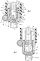
- Feed mechanism 16 is shown in its retracted and extended positions in Figures 5 and 6, respectively.
- handle 100 is rotated about the feed gear's axis.
- Feed gear 80 rotates about its axis thereby translating rack 72 downward and parallel to first axis A.
- Rack 72 translates quill 60 and spindle 110 which is secured to quill 60 by retaining rings 124.
- Spindle 110 slides downward along splines 130,138 as shaft 134 rotatingly drives spindle 110 and cutting tool 18.
- Spindle 110 and cutting tool 18 are fully extended when stop 152 engages lip 156 on inner surface 116 of top portion 112 of spindle 110.
- handle 100 is rotated about the feed gear's axis in an opposite direction thereby translating the feed mechanism's components along first axis A in the opposite direction.
- Spindle 110 and cutting tool 18 are fully retracted when stop 152 engages lip 158 on inner surface 116 of bottom portion 114.
- the cutting tool of the present invention is specially adapted to be used with the compact drill design of the present invention. Specifically, the various cutting angles of previously known tools have been changed and a taper has been added to the cutting portion of the tool as explained in more detail below.
- bottom portion 114 of spindle 110 has a hole 170 along first axis A with a pin 172 offset from and transverse to first axis A.
- Hole 170 is adapted to receive a shank portion 180 of cutting tool 18.
- Shank portion 180 has a flat 174 that leads into an annular recess 175 in a radial portion of the perimeter of shank portion 180.
- Cutting tool 18 is inserted into hole 170 by aligning flat 174 with pin 172 so that cutting tool 18 may be inserted into hole 170.
- To lock cutting tool 18 into hole 170 cutting tool 18 is rotated so that pin 172 is received within annular recess 175.
- a rubber seal 176 or O-ring is received within an annular groove 178 on the shank portion 180 to prevent debris from entering hole 170 which would make removal of cutting tool 18 from hole 170 more difficult.
- cutting tool 18 has shank portion 180 and a cutting portion 182 extending from shank portion 180 along first axis A.
- Cutting portion 182 includes a cutting surface 184 and inner 185 and outer 186 surfaces that taper back towards shank portion 180.
- Inner surface 185 of cutting portion 182 tapers in the range of 0.010 - 0.025" over its length with a 0.016 - 0.020" range being preferred.
- Outer surface 186 of cutting portion 182 taper in the range of 0.015 - 0.035" over its length with a 0.020 - 0.024" range being preferred.
- the inner and outer taper is necessary to prevent binding as the hole is being machined by cutting tool 18 in the work piece.
- Cutting surface 184 has a plurality of cutting teeth 200.
- each of the cutting teeth 200 have cutting edges 202, 204 and 206. It should be appreciated by one of ordinary skill in the art that more or less cutting edges could be used.
- outside cutting edge 204 has an angle B', the outside inclination angle, in the range of 5-15° with the preferred angle being 10°.
- a typical outside inclination angle of an ordinary cutter is approximately 35°.
- Cutting edge 202 has an angle X, i.e., an inside inclination angle, in the range of 20-30° with the preferred angle being 25°. In a typical cutter, the angle is approximately 15°.
- the inner most cutting edge 206 has the same inside inclination angle as the cutting edge 202.
- the cutter quickly stabilizes itself in the workpiece.
- the outer cutting edges 204 initially cut the workpiece surface so that the cutting tool immediately seats itself in the intended area of the workpiece.
- the inner cutting edges 202 and 206 begin to cut and together form a kerf.
- the teeth 202, 204 and 206 continue to cut within the kerf until the hole is formed, leaving a slug in the cutting tool.
- the screw 152 engages a slug ejector, not shown, to eject the slug.
- Outer surface 186 has a plurality of helical flutes 194 for channeling chips away from the work piece.
- the angle ⁇ of the helix is in the range of 22 - 30° with the preferred angle being 25° compared with a typical angle of normal cutters being 15°.
- Helical flutes 194 include gullets 196 for facilitating the discharge of chips.
- angles of the cutting tool the present invention ensure that the tool "bites” into the work piece and does not skid or twist off as a prior art tool would when used with the drill of the present invention. Moreover, the angles also accommodate the reduced power, speed, and torque of the smaller drill and magnetic base of the present invention as compared to the larger prior art designs.
Landscapes
- Engineering & Computer Science (AREA)
- Mechanical Engineering (AREA)
- Drilling Tools (AREA)
Applications Claiming Priority (3)
| Application Number | Priority Date | Filing Date | Title |
|---|---|---|---|
| US12449199P | 1999-03-15 | 1999-03-15 | |
| US124491P | 1999-03-15 | ||
| EP00914918A EP1177061B1 (de) | 1999-03-15 | 2000-03-08 | Selbsthaftende bohr- und fräsvorrichtung |
Related Parent Applications (2)
| Application Number | Title | Priority Date | Filing Date |
|---|---|---|---|
| EP00914918.8 Division | 2000-03-08 | ||
| EP00914918A Division EP1177061B1 (de) | 1999-03-15 | 2000-03-08 | Selbsthaftende bohr- und fräsvorrichtung |
Publications (3)
| Publication Number | Publication Date |
|---|---|
| EP1361011A2 true EP1361011A2 (de) | 2003-11-12 |
| EP1361011A3 EP1361011A3 (de) | 2003-11-19 |
| EP1361011B1 EP1361011B1 (de) | 2005-09-21 |
Family
ID=29252115
Family Applications (1)
| Application Number | Title | Priority Date | Filing Date |
|---|---|---|---|
| EP03015931A Expired - Lifetime EP1361011B1 (de) | 1999-03-15 | 2000-03-08 | Ringförmiges Schneidwerkzeug für selbsthaftende Bohrvorrichtung |
Country Status (1)
| Country | Link |
|---|---|
| EP (1) | EP1361011B1 (de) |
Cited By (1)
| Publication number | Priority date | Publication date | Assignee | Title |
|---|---|---|---|---|
| CN104772515A (zh) * | 2015-03-17 | 2015-07-15 | 中国科学院等离子体物理研究所 | 一种用于核聚变装置包层管路管头切割的机构 |
Citations (6)
| Publication number | Priority date | Publication date | Assignee | Title |
|---|---|---|---|---|
| US3609056A (en) * | 1969-06-05 | 1971-09-28 | Everett D Hougen | Hole cutter |
| US4322188A (en) * | 1980-09-02 | 1982-03-30 | Hougen Everett D | Annular hole cutter |
| US4452554A (en) * | 1981-09-21 | 1984-06-05 | Hougen Everett D | Annular hole cutter |
| GB2182588A (en) * | 1985-11-11 | 1987-05-20 | Dennis Hubbard | Annular hole cutter |
| EP0333651A1 (de) * | 1988-03-18 | 1989-09-20 | Everett D. Hougen | Ringlochschneider mit radialer Aussparung |
| GB2319739A (en) * | 1997-07-08 | 1998-06-03 | Bradford Tool And Gauge Ltd | Hole cutting tool |
-
2000
- 2000-03-08 EP EP03015931A patent/EP1361011B1/de not_active Expired - Lifetime
Patent Citations (6)
| Publication number | Priority date | Publication date | Assignee | Title |
|---|---|---|---|---|
| US3609056A (en) * | 1969-06-05 | 1971-09-28 | Everett D Hougen | Hole cutter |
| US4322188A (en) * | 1980-09-02 | 1982-03-30 | Hougen Everett D | Annular hole cutter |
| US4452554A (en) * | 1981-09-21 | 1984-06-05 | Hougen Everett D | Annular hole cutter |
| GB2182588A (en) * | 1985-11-11 | 1987-05-20 | Dennis Hubbard | Annular hole cutter |
| EP0333651A1 (de) * | 1988-03-18 | 1989-09-20 | Everett D. Hougen | Ringlochschneider mit radialer Aussparung |
| GB2319739A (en) * | 1997-07-08 | 1998-06-03 | Bradford Tool And Gauge Ltd | Hole cutting tool |
Cited By (2)
| Publication number | Priority date | Publication date | Assignee | Title |
|---|---|---|---|---|
| CN104772515A (zh) * | 2015-03-17 | 2015-07-15 | 中国科学院等离子体物理研究所 | 一种用于核聚变装置包层管路管头切割的机构 |
| CN104772515B (zh) * | 2015-03-17 | 2018-05-04 | 中国科学院等离子体物理研究所 | 一种用于核聚变装置包层管路管头切割的机构 |
Also Published As
| Publication number | Publication date |
|---|---|
| EP1361011B1 (de) | 2005-09-21 |
| EP1361011A3 (de) | 2003-11-19 |
Similar Documents
| Publication | Publication Date | Title |
|---|---|---|
| US6280123B1 (en) | Self-adhering drill and cutter | |
| CA2457241C (en) | Universal quick change hole saw arbor | |
| EP2184124B1 (de) | Bohrwerkzeug | |
| JPH06198511A (ja) | 切削具付バリ取り工具 | |
| SE0202326D0 (sv) | Hole saw arbor | |
| US7150589B2 (en) | Deburring tool | |
| US20120237306A1 (en) | Hole saw | |
| US9623491B2 (en) | Beveling / chamfering tool—router head for metal | |
| US6092964A (en) | Rivet removal tool and method | |
| WO2018052118A1 (ja) | コアドリル | |
| CN100531978C (zh) | 手持式工具机 | |
| US20030035694A1 (en) | Boring bit for boring holes in wood pieces | |
| EP1361011A2 (de) | Ringförmiges Schneidwerkzeug für selbsthaftende Bohrvorrichtung | |
| US11850668B2 (en) | Cutter-spline drive for portable electrical drilling assembly | |
| US20050031422A1 (en) | Cutter assembly | |
| JP2002522243A (ja) | ホールカッター | |
| MXPA01009235A (en) | Self-adhering drill and cutter | |
| JPH1071517A (ja) | 孔開け工具及び孔開け工具用芯出し治具並びに孔開け工具による孔開け方法 | |
| EP0019018A1 (de) | Bohrwerkzeuge | |
| CN220681108U (zh) | 内螺纹木工开孔器 | |
| CN214443576U (zh) | 一种手持式快速倒角机 | |
| CN221435042U (zh) | 一种钻锪一体式复合刀具 | |
| WO1998001252A1 (en) | Combined cross-head screwdriver and countersinking tool | |
| US20210394283A1 (en) | Spherical cutting tool, system and method of using | |
| JP4372562B2 (ja) | ドリル用ストッパー |
Legal Events
| Date | Code | Title | Description |
|---|---|---|---|
| PUAI | Public reference made under article 153(3) epc to a published international application that has entered the european phase |
Free format text: ORIGINAL CODE: 0009012 |
|
| PUAL | Search report despatched |
Free format text: ORIGINAL CODE: 0009013 |
|
| 17P | Request for examination filed |
Effective date: 20030724 |
|
| AC | Divisional application: reference to earlier application |
Ref document number: 1177061 Country of ref document: EP Kind code of ref document: P |
|
| AK | Designated contracting states |
Kind code of ref document: A2 Designated state(s): AT BE CH CY DE DK ES FI FR GB GR IE IT LI LU MC NL PT SE |
|
| AK | Designated contracting states |
Kind code of ref document: A3 Designated state(s): AT BE CH CY DE DK ES FI FR GB GR IE IT LI LU MC NL PT SE |
|
| 17Q | First examination report despatched |
Effective date: 20040220 |
|
| AKX | Designation fees paid |
Designated state(s): AT BE CH CY DE DK ES FI FR GB GR IE IT LI LU MC NL PT SE |
|
| GRAP | Despatch of communication of intention to grant a patent |
Free format text: ORIGINAL CODE: EPIDOSNIGR1 |
|
| GRAS | Grant fee paid |
Free format text: ORIGINAL CODE: EPIDOSNIGR3 |
|
| GRAA | (expected) grant |
Free format text: ORIGINAL CODE: 0009210 |
|
| AC | Divisional application: reference to earlier application |
Ref document number: 1177061 Country of ref document: EP Kind code of ref document: P |
|
| AK | Designated contracting states |
Kind code of ref document: B1 Designated state(s): AT BE CH CY DE DK ES FI FR GB GR IE IT LI LU MC NL PT SE |
|
| PG25 | Lapsed in a contracting state [announced via postgrant information from national office to epo] |
Ref country code: NL Free format text: LAPSE BECAUSE OF FAILURE TO SUBMIT A TRANSLATION OF THE DESCRIPTION OR TO PAY THE FEE WITHIN THE PRESCRIBED TIME-LIMIT Effective date: 20050921 Ref country code: AT Free format text: LAPSE BECAUSE OF FAILURE TO SUBMIT A TRANSLATION OF THE DESCRIPTION OR TO PAY THE FEE WITHIN THE PRESCRIBED TIME-LIMIT Effective date: 20050921 Ref country code: FI Free format text: LAPSE BECAUSE OF FAILURE TO SUBMIT A TRANSLATION OF THE DESCRIPTION OR TO PAY THE FEE WITHIN THE PRESCRIBED TIME-LIMIT Effective date: 20050921 Ref country code: LI Free format text: LAPSE BECAUSE OF FAILURE TO SUBMIT A TRANSLATION OF THE DESCRIPTION OR TO PAY THE FEE WITHIN THE PRESCRIBED TIME-LIMIT Effective date: 20050921 Ref country code: CH Free format text: LAPSE BECAUSE OF FAILURE TO SUBMIT A TRANSLATION OF THE DESCRIPTION OR TO PAY THE FEE WITHIN THE PRESCRIBED TIME-LIMIT Effective date: 20050921 Ref country code: BE Free format text: LAPSE BECAUSE OF FAILURE TO SUBMIT A TRANSLATION OF THE DESCRIPTION OR TO PAY THE FEE WITHIN THE PRESCRIBED TIME-LIMIT Effective date: 20050921 Ref country code: IT Free format text: LAPSE BECAUSE OF FAILURE TO SUBMIT A TRANSLATION OF THE DESCRIPTION OR TO PAY THE FEE WITHIN THE PRESCRIBED TIME-LIMIT;WARNING: LAPSES OF ITALIAN PATENTS WITH EFFECTIVE DATE BEFORE 2007 MAY HAVE OCCURRED AT ANY TIME BEFORE 2007. THE CORRECT EFFECTIVE DATE MAY BE DIFFERENT FROM THE ONE RECORDED. Effective date: 20050921 |
|
| REG | Reference to a national code |
Ref country code: GB Ref legal event code: FG4D |
|
| REG | Reference to a national code |
Ref country code: CH Ref legal event code: EP |
|
| REG | Reference to a national code |
Ref country code: IE Ref legal event code: FG4D |
|
| REF | Corresponds to: |
Ref document number: 60022795 Country of ref document: DE Date of ref document: 20051027 Kind code of ref document: P |
|
| PG25 | Lapsed in a contracting state [announced via postgrant information from national office to epo] |
Ref country code: DK Free format text: LAPSE BECAUSE OF FAILURE TO SUBMIT A TRANSLATION OF THE DESCRIPTION OR TO PAY THE FEE WITHIN THE PRESCRIBED TIME-LIMIT Effective date: 20051221 Ref country code: GR Free format text: LAPSE BECAUSE OF FAILURE TO SUBMIT A TRANSLATION OF THE DESCRIPTION OR TO PAY THE FEE WITHIN THE PRESCRIBED TIME-LIMIT Effective date: 20051221 Ref country code: SE Free format text: LAPSE BECAUSE OF FAILURE TO SUBMIT A TRANSLATION OF THE DESCRIPTION OR TO PAY THE FEE WITHIN THE PRESCRIBED TIME-LIMIT Effective date: 20051221 |
|
| PG25 | Lapsed in a contracting state [announced via postgrant information from national office to epo] |
Ref country code: ES Free format text: LAPSE BECAUSE OF FAILURE TO SUBMIT A TRANSLATION OF THE DESCRIPTION OR TO PAY THE FEE WITHIN THE PRESCRIBED TIME-LIMIT Effective date: 20060101 |
|
| PG25 | Lapsed in a contracting state [announced via postgrant information from national office to epo] |
Ref country code: PT Free format text: LAPSE BECAUSE OF FAILURE TO SUBMIT A TRANSLATION OF THE DESCRIPTION OR TO PAY THE FEE WITHIN THE PRESCRIBED TIME-LIMIT Effective date: 20060221 |
|
| NLV1 | Nl: lapsed or annulled due to failure to fulfill the requirements of art. 29p and 29m of the patents act | ||
| PG25 | Lapsed in a contracting state [announced via postgrant information from national office to epo] |
Ref country code: MC Free format text: LAPSE BECAUSE OF NON-PAYMENT OF DUE FEES Effective date: 20060331 Ref country code: LU Free format text: LAPSE BECAUSE OF NON-PAYMENT OF DUE FEES Effective date: 20060331 |
|
| REG | Reference to a national code |
Ref country code: CH Ref legal event code: PL |
|
| PLBE | No opposition filed within time limit |
Free format text: ORIGINAL CODE: 0009261 |
|
| STAA | Information on the status of an ep patent application or granted ep patent |
Free format text: STATUS: NO OPPOSITION FILED WITHIN TIME LIMIT |
|
| 26N | No opposition filed |
Effective date: 20060622 |
|
| PG25 | Lapsed in a contracting state [announced via postgrant information from national office to epo] |
Ref country code: FR Free format text: LAPSE BECAUSE OF FAILURE TO SUBMIT A TRANSLATION OF THE DESCRIPTION OR TO PAY THE FEE WITHIN THE PRESCRIBED TIME-LIMIT Effective date: 20061020 |
|
| EN | Fr: translation not filed | ||
| PGFP | Annual fee paid to national office [announced via postgrant information from national office to epo] |
Ref country code: GB Payment date: 20070307 Year of fee payment: 8 |
|
| PGFP | Annual fee paid to national office [announced via postgrant information from national office to epo] |
Ref country code: DE Payment date: 20070308 Year of fee payment: 8 |
|
| PGFP | Annual fee paid to national office [announced via postgrant information from national office to epo] |
Ref country code: IE Payment date: 20070313 Year of fee payment: 8 |
|
| GBPC | Gb: european patent ceased through non-payment of renewal fee |
Effective date: 20080308 |
|
| PG25 | Lapsed in a contracting state [announced via postgrant information from national office to epo] |
Ref country code: FR Free format text: LAPSE BECAUSE OF FAILURE TO SUBMIT A TRANSLATION OF THE DESCRIPTION OR TO PAY THE FEE WITHIN THE PRESCRIBED TIME-LIMIT Effective date: 20050921 Ref country code: CY Free format text: LAPSE BECAUSE OF FAILURE TO SUBMIT A TRANSLATION OF THE DESCRIPTION OR TO PAY THE FEE WITHIN THE PRESCRIBED TIME-LIMIT Effective date: 20050921 |
|
| REG | Reference to a national code |
Ref country code: IE Ref legal event code: MM4A |
|
| PG25 | Lapsed in a contracting state [announced via postgrant information from national office to epo] |
Ref country code: IE Free format text: LAPSE BECAUSE OF NON-PAYMENT OF DUE FEES Effective date: 20080310 Ref country code: DE Free format text: LAPSE BECAUSE OF NON-PAYMENT OF DUE FEES Effective date: 20081001 |
|
| PG25 | Lapsed in a contracting state [announced via postgrant information from national office to epo] |
Ref country code: GB Free format text: LAPSE BECAUSE OF NON-PAYMENT OF DUE FEES Effective date: 20080308 |