EP1360864B1 - Paging-verfahren und system für ein funkzugriffsnetzwerk - Google Patents
Paging-verfahren und system für ein funkzugriffsnetzwerk Download PDFInfo
- Publication number
- EP1360864B1 EP1360864B1 EP02712129A EP02712129A EP1360864B1 EP 1360864 B1 EP1360864 B1 EP 1360864B1 EP 02712129 A EP02712129 A EP 02712129A EP 02712129 A EP02712129 A EP 02712129A EP 1360864 B1 EP1360864 B1 EP 1360864B1
- Authority
- EP
- European Patent Office
- Prior art keywords
- paging
- network
- paging message
- radio access
- network controlling
- Prior art date
- Legal status (The legal status is an assumption and is not a legal conclusion. Google has not performed a legal analysis and makes no representation as to the accuracy of the status listed.)
- Expired - Lifetime
Links
Images


Classifications
-
- H—ELECTRICITY
- H04—ELECTRIC COMMUNICATION TECHNIQUE
- H04W—WIRELESS COMMUNICATION NETWORKS
- H04W68/00—User notification, e.g. alerting and paging, for incoming communication, change of service or the like
- H04W68/12—Inter-network notification
Definitions
- the present invention relates to a method and system for providing a paging function in a RAN (radio access network), e.g. a UTRAN (UMTS Terrestrial Radio Access Network), GERAN (GSM / EDGE Radio Access Network) or any future potential RAN such as IP-RAN (Internet Protocol RAN), of a cellular network, such as a UMTS (Universal Mobile Telecommunications System) network.
- a RAN radio access network
- GSM / EDGE Radio Access Network GSM / EDGE Radio Access Network
- IP-RAN Internet Protocol RAN
- UMTS Universal Mobile Telecommunications System
- GSM Global System for Mobile communications
- the general trend is for data applications to generate increasingly bursty data streams; this results in inefficient use of circuit switched connections.
- fixed networks have seen an enormous growth in data traffic, not at least because of the rise of Internet access demand, such that it is to be supposed that mobile networks will spread as technology and customer expectations move on.
- the current GSM switch network is based on narrow band ISDN (Integrated Services Digital Network) circuits, so that the reason for rate limitations moves from the access network to the core network.
- ISDN Integrated Services Digital Network
- the new GPRS (General Packet Radio Services) network will offer operators the ability to charge by the packet, and support data transfer across a high-speed network at up to eight times slot radio interface capacity.
- GPRS introduces two new nodes into the GSM network, a SGSN (Serving GPRS Support Node) and a GGSN (Gateway GPRS Support Node).
- the SGSN keeps track of the location of the mobile terminal within its service area and sends and receives packets to/from the mobile terminal, passing them on or receiving them from the GGSN.
- the GGSN then converts the GSM packets into other packet protocols (e.g. IP or X.25) and sends them out into other networks.
- UMTS will deliver advanced information directly to people and provide them with access to new and innovative services. It will offer mobile personalized communications to the mass market regardless of location, network or terminal used.
- two or more CN (core network) domains can be connected to one RNC (radio network controller) or a similar unit, e.g. RNAS (Radio access network Access Server), in the radio access network.
- RNC radio network controller
- RNAS Radio access network Access Server
- a UE user equipment
- MS mobile station
- MS mobile station
- MM mobility management
- CS MSCs Mobile Switching Centers
- PS packet switched 3G SGSNs
- MM idle When an MS has no CS services in use, the MSC sees its MM state "MM idle”.
- PMM packet mobility management
- the MS performs either handovers, cell updates or URA (UMTS Registration Area) updates, depending of the channels it uses and the level of activity it has shown lately.
- the MS is in the MM state "MM-connected" (via MSC) or in the PMM state "PMM-connected” (via 3G SGSN).
- the RNC includes both CRNC-C (Controlling RNC C-plane) and SRNC-C (Serving RNC C-plane) functionalities in the same physical entity.
- the CN sees RNCs mapped to LAs (location areas) in the MSC or to RAs (routing areas) in the 3G SGSN.
- the MS may have only a PS connection in use. Thus, it is PMM-connected in the 3G SGSN and RRC-connected in the RNC, but the MSC sees the MS in state "MM-idle". If an incoming call arrives at the MSC, the MSC sends a paging message to all RNCs, which serve the LA the MS, has registered to. If there are several RNCs serving the same LA, paging is sent to the RNC(s) where (an) RRC connection(s) exist(s), but also to RNC(s), which do not know the MS. Thus, unnecessary extra pagings are performed.
- the MS may have an NRT PDP (Non-Real Time Packet Data Protocol) context in use, the RAB (Radio Access Bearer) of which has been released due to low level of activity.
- NRT PDP Non-Real Time Packet Data Protocol
- the MS establishes a CS call and enters to the MM state "RRC-connected".
- the 3G SGSN may receive data packets related to the NRT PDP context.
- the 3G SGSN assumes that the MS is in the PMM state "PMM-idle" and sends a paging request to all RNCs, which are mapped to serve the corresponding RA.
- PMM-idle the MS's RRC connection already exists, while all other RNCs perform unnecessary extra pagings.
- Document WO 9957935 relates to a radio acces network portion of a telecommunications network wherein a paging control node, in order to page a mobile station in a multicell area, sends paging messages to each of the base stations serving the multicell area controlled by the paging control node and sends a paging message to any other control nodes which control base stations serving cells in the multicell area by consulting a paging table.
- RAN radio access network
- the paging coordination means are arranged to receive pagings and to distribute the pagings to other network controlling devices.
- the whole access network is seen as one mapping in the core network. This does not necessarily require changes to standards, but it makes configuration easier.
- the invention makes a forced location area update concept unnecessary in UMTS. Furthermore, the invention reduces signalling load on radio interface paging channels, since a mobile that already has an RRC connection would never be paged from "unnecessary" cells.
- Future IP based radio access networks may provide a distribution of functions and a "full-mesh" IPv6 (IP Version 6) network between all base stations and controllers, which makes this kind of optimization a very attractive feature.
- IPv6 IP Version 6
- a lu is an interface between a RNC and a CN
- a lub is an interface between a RNC and a Node B, which is a logical node responsible for radio transmission/reception in one or more cells to/from the UE.
- a peculiar 'forced/prohibited' LA/RA mechanism as included in the UTRAN Release' 99 specifications for mobiles in connected mode is no longer required.
- the paging coordination means may have storing means for storing real time information about mobile terminals having a connection to the radio access network.
- Such real time information may be identification information of the mobile, e.g. the International Mobile Subscriber Identity or like.
- the identification information about the mobile terminal is stored in the storing means and the identification information is removed from the storing means when the connection to the radio access network of the mobile terminal is terminated.
- the distribution of pagings is based on a paging message provided to the paging coordination means, e.g. the paging message may include information about a location area, a routing area, a cell and/or cell resources, and a real time mapping of mobile terminals being connected to the radio access network provided by the storing means. Then, the pagings are directed to mobile terminals located within the area of the radio access network. Therefore, unnecessary pagings to network elements are avoided, e.g. cells, which are not related to the addressed mobile terminal.
- the paging coordination means may be a paging server or could be implemented in a predetermined radio access network access server or a predetermined radio network controller.
- the paging message is provided to the paging coordination means. Based on the paging message and the information stored by the coordination means other network controlling devices are de-termined to which the paging message is to be routed. Thus, the pagings are distributed from the central paging coordination means to the determined network controlling devices.
- determining other network controlling devices comprises checking with at least one other paging coordination function of the radio access network whether another paging coordination function has a packet or circuit switched connection to the mobile terminal addressed by the paging and then distributing the paging message to the determined other paging function based on the result of the checking step.
- determining other network controlling devices includes checking based on the paging message and the information stored within the coordination function which other network controlling devices the paging message has to be routed to.
- the access network comprises many RNCs and/or RNASs
- the information required for paging or mobility management (MM) is provided at one place in one location area (LA) or routing area (RA).
- LA location area
- RA routing area
- the core network (CN) sends a paging request
- the request does not have to be transmitted to many RNCs and/or RNASs and extra paging can be avoided in the access networks, e.g. in both GERAN and UTRAN.
- a paging coordination is possible despite of the number of different CNs, and an opportunity is given to implement UE specific signalling in servers, which are not dependent on the areas.
- the CN may see the access network (e.g. IP RAN) as one address, because all the pagings can be directed to one server. Hence, there is no need for area-UE specific signalling element mappings in the CN.
- the paging function in the access network will be centralized to one or several servers. This gives the possibility to paging coordination in different access networks (e.g. UTRAN and GERAN).
- SRNC-C's UE specific functions may be distributed to elements, which have no dependencies to any area. This also gives an opportunity to distribute the load caused by SRNC-C's UE specific functions evenly among those elements.
- the IP RAN is an example for an IP based RAN for providing access for UEs of multiple radio technologies to UMTS based CNs. Some examples of these radio technologies are GSM, EDGE, WCDMA, and/or WLAN.
- the first applications to be implemented in IP RAN are GERAN (GSM / EDGE RAN), GSM and UTRAN (UMTS Terrestrial Radio Access Network).
- RAN functionality will be distributed to several servers, which will be connected to an IPv6 based network.
- Fig. 1 shows an IP RAN architecture.
- the architecture can be divided into a control plane (C-plane) functionality and a user plane (U-plane) functionality, which are both connected to a Node B 20.
- the Node B 20 is a logical network node responsible for transmission/reception in one or more radio cells to/from a UE or mobile terminal.
- the Node B 20 terminates the lub interface towards the RNC functionality.
- the Node B 20 is connected via an lubU interface to a U-plane Controlling Radio Network Controller CRNCu 53 which has the overall control of the logical resources of its RAN access points.
- the CRNCu 53 is connected via an lurU interface to a U-plane Serving RNC SRNCu 54 with an MDC (Macro Diversity Combining) function.
- the MDC function is an RNC related user and control plane function, which is adapted to choose the better signal from alternative ones according to quality parameters.
- the lur interface is a logical interface between two RNCs.
- the SRNCu 54 then provides a connection via a packet switched lu-psU interface to a gateway GW 60 which provides access to a core network CN.
- U-plane elements are connected via respective interfaces Ctrl-C, Ctrl-S and Ctrl-G, respectively, to a C-plane CRNC CRNCc 51 and C-plane SRNC SRNCc 52, respectively, of the C-plane functionality.
- the CRNCc 51 and the SRNCc 52 are connected to each other via an lurC interface.
- the Node B 20 is connected via an lubC interface to the CRNCc 51, and a connection to the core network CN can be established via the SRNCc 52 and an lu-psC interface or an lu-cb interface.
- SRNC-C functions SRNC-C functions
- UE related function RANAP Radio Access Network Application Protocol
- RRC connection management • Establishment, reconfiguration, and release or an RRC (Radio Resource Control) connection
- RAB management • Establishment, reconfiguration, and release a RAB (Radio Access Bearer) to the UE Admission Control • Bearer admission control including allocation of air interface L2 and L1 parameters, decision of radio channel request and modification • QoS (Quality of Service) negotiation across the lu interface
- Radio handover control including HO decision and resource reservation management
- Network HO control including relocation of lu connection and L2 processing entity, or anchoring • Control and processing of UE measurement • Selection of the CRRM, and CRRM enquiry for HO candidate Network handover control • Decision and execution of the relocation of the lu connection • Decision and control of the anchoring of the BTS (Base Transceiver Station).
- the SRNCc 52 is connected via an Lb interface to a Serving Mobile Location Center SMLC 90 and via an luc2 interface to a Common Radio Resources Management CRRM 40 which is connected via a luc3 interface to an Operation and Maintenance O&M server 3 for controlling logical resources owned by the RNC functionality.
- the O&M server 3 is connected via an lubOM interface to the CRNCc 51 and provides access to an OSS (Operations Support System) via an NWI3 interface.
- OSS Operating Support System
- the CRNCc 51 and the SRNCc 52 are connected to a corresponding peer CRNCc 510 and peer SRNCc 520, respectively, of the IP RAN.
- Fig. 2 shows an IPRC (IP Radio Controller) architecture, which may be implemented in the IP RAN.
- the IPRC consists of many SRNC-Cs (called RNAS 5) which are independent of any LAs, RAs or other areas, and which perform only an MS or UE specific signalling.
- RNAS IP Radio Controller
- the IPRC comprises an O&M server 3 and an RNAS 5 which is connected via respective signalling connections to a Common Resource Management Server (CRMS) 4, to an A Interface Gateway (AGW) 7 for providing a core network access via the A Interface, to a Radio Network Gateway (RNGW) 6 which provides a data gateway functionality between an IP-BTS (IP Base Transceiver Station) 10 and a packet switched lu-PS user plane or a circuit switched lu-CS user plane (via an lu Interface Gateway (IUGW) 8), to a Base Station Gateway (BSGW) 2 of the IP-BTS 10, and to a BTS 1 of the IP-BTS.
- IP-BTS IP Base Transceiver Station
- IUGW lu Interface Gateway
- the paging in the RAN is coordinated.
- a LA known by the core network
- the CN needs to send the paging only to one node in the RAN and the RAN internally controls the actual paging area.
- This 'coordination' can be implemented in different ways as described in the first and second preferred embodiments with reference to Fig. 3 and Figs. 4 and 5A to 5D, respectively.
- Fig. 3 shows an architecture of an RNAS domain and a corresponding paging signalling according to the first preferred embodiment.
- a centralized paging server 100 is provided in the RNAS domain, where all paging messages from the CNs are always routed to.
- This paging server 100 has real-time knowledge of all mobile terminals or UEs in "RRC connected state" within one RAN. Thus, if a paging message towards such a mobile terminal is received, the paging server 100 can forward the message to the correct BSC (Base Station Controller) or RNC or RNAS (etc.), which currently controls the connection of the concerned mobile terminal.
- BSC Base Station Controller
- RNC Radio Network Controller
- the paging server 100 is connected via a signalling connection to a CRS (Cell Resource Server) functionality 11 in the IP-BTS 11.
- This signalling connection is used in the UL (up link) direction for an RNAS selection signalling, and in the DL (down link) direction for RRC idle mode pagings.
- the paging server 100 comprises or has allocated a database 15 in which mapping information regarding e.g. IMSI (International Mobile Subscriber Identity) to RNAS address mappings and LA/RA/cell-CRS mappings and other mappings required for paging and/or mobility management purposes are stored.
- IMSI International Mobile Subscriber Identity
- the paging server 100 is connected to the RNAS 5 via another signalling connection through which creations and deletions of IMSI to RNAS address associations and other mapping information can be signalled in the UL direction, and through which RRC connected mode pagings can be initiated in the DL direction. Additionally, respective signalling connections between the paging server 100 and the CN may be provided to transmit lu-CS and/or lu-PS and A and/or Gb interface control plane signallings and LA/RA specific paging request. Similar signalling connections may be provided for the RNAS 5 to provide corresponding control plane signalling except for paging requests.
- the RNAS 5 may be arranged to forward pagings in cell shared and cell dedicated states via a DL signalling connection to the Base Station Gateway BSGW 2 of the IP-BTS 10. Additionally, GERAN pagings in GRA PCH (GERAN RA Paging Channel) states and UTRAN pagings in the URA PCH (UTRAN RA Paging Channel) states may be forwarded to the CRS functionality 11 of the IP-BTS 10 via a corresponding signalling connection. Packet data can be transmitted via corresponding data connections from the CRS functionality 11 and a CGW (Cell Gateway) functionality 12 through the BSGW 2 of the IP-BTS 10 and the RNGW 6 to the lu-PS user plane of the CN.
- GRA PCH GERAN RA Paging Channel
- URA PCH UTRAN RA Paging Channel
- a signalling may be performed between the BSGW 2 and the RNAS 5 to initiate cell updates, GRA/URA updates, and/or BTS anchorings and relocations.
- the BSGW 2 may be arranged to initiate a paging in the GERAN cell shared state and/or a paging in the ready state.
- a signalling may be performed between the RNGW 6 and the RNAS 5 to initiate paging needed notifications in the GRA PCH and URA PCH states.
- the RNAS 5 may be connected via respective signalling connections to other RNASs of other IPRCs to initiate RNAS relocations.
- an RNAS selection needs to be performed when the MS or UE moves from an idle to a connected mode, when the MS or UE performs a location registration or for idle mode paging, and in the connected mode during a relocation.
- the selection can be performed by selecting a default RNAS for the initial access from the MS or UE and for a CN initiated idle mode paging.
- the default RNAS is associated with the LA/RA, and the answer for the initial access might be coming from another RNAS.
- the RNAS can be selected based on e.g. the network topology or load.
- the CRMS 4 shown in Fig. 2 could be involved in the RNAS selection management.
- the paging server 100 serves as an RNAS receiving idle mode paging requests for a specific LA/RA, and as a default RNAS in an initial access. As indicated by the arrows in Fig. 3 , the paging server 100 receives an idle mode paging request from the CN and routes the paging request to the CRS functionality 11 of the IP-BTS 10. The CRS functionality 11 sends an initial access to the paging server 100 which routes the initial access to the allocated RNAS, e.g. the RNAS 5, based on the mapping information in the database 15. The allocated RNAS 5 issues an initial access response to the CRS functionality 1.
- paging messages from the CN are routed by the paging server 100 to the allocated RNAS 5 which then routes the paging messages to the BSGW 2.
- the paging server 100 is informed by the allocated RNAS 5 when the RNAS for the RRC connection has changed.
- an MS When an MS establishes an RRC connection in an IP RAN environment according to Fig. 1 , its IMSI and SRNC-C UE specific functions server identifier are stored to the database 15 at the paging server 100.
- the IMSI is provided to the IP RAN by the CN after security procedures have been executed.
- the MS releases the RRC connection, the MS's information is removed from the database 15.
- the Paging server 100 has LA-RA-cell-CRNC-C address mappings stored in the database 15, to be able to forward pagings to CRNC-Cs.
- the CN When the CN sees the MS in the state "PMM-idle” or "MM-idle", it sends a paging request towards the paging server 100.
- the paging server 100 checks from its database 15, whether an MS's RRC connection already exists. If there is an existing RRC connection, the paging is forwarded to the corresponding SRNC-C UE specific functional element. This situation may occur, if the MS for example has an ongoing PS connection but no CS calls. If an RRC connection does not exist, the paging server 100 distributes the paging to the CRNC-Cs of the whole LA/RA.
- the first embodiment shown in Fig. 3 is not restricted to a single paging server 100, but there can be arranged multiple paging servers 100 with a (standard) interface between them.
- the paging server 100 may be arranged as a function inside one RNAS, wherein the RNAS-RNAS interface function has to be adapted correspondingly so as to support also the paging server signalling.
- the database 15 of the paging server 100 can be distributed for the whole RAN (e.g. IP RAN).
- the coordination functionality can be implemented as a part of a network controller, e.g. a BSC, RNC, RNAS or corresponding controller.
- a network controller receives a paging message from the CN, it checks from other possible controllers whether they already have a connection for this MS or UE. This could be implemented e.g. so that CN always sends the paging message to only one controller, the message including a list of controllers (or cells) belonging to the LA/RA of the paged MS or UE.
- the controller receiving the paging message (“first controller") can now send a request for all the other controllers in the list and if one of them already has a connection to this MS or UE, forward the paging message from the CN to that controller. If none of the asked controllers have already a connection with the MS or UE, the first controller can coordinate the idle mode paging either by forwarding the paging message directly to all cells in the LA/RA or by requesting the other controllers to page on their cells. This selection depends on the RAN architecture, e.g. whether there is tight relation between cells and controllers or if any controller can access any cell (which may be the case in the future IP-RAN network shown in Fig. 1 ).
- the CN sends the paging message to one of the RNCs or RNASs together with a list of RNCs or RNASs in the respective RA or LA, and then the RNC or RNAS which received the paging message does the remaining procedures, e.g. checking whether the paged mobile terminal is active in the cover area of one of other RNCs or RNASs and, if not, executing an idle mode paging in this RA or LA (perhaps with the help of the other RNASs).
- Fig. 4 shows an architecture of an RNAS domain and a corresponding paging signalling according to the second preferred embodiment.
- the architecture corresponds to the architecture according to Fig. 3 , while the paging server 100 has been replaced by a first RNAS 5-1.
- the function of the elements corresponding to those elements shown in Fig. 3 are similar and will therefore not be described again in this second preferred embodiment.
- the first RNAS 5-1 connected to a CN via an lu control plane for paging requests for a first location area LA1
- a second RNAS 5-2 connected to the core network via an lu control plane for paging requests for second location areas LA3, LA4 are connected via a signalling connection.
- the first RNAS 5-1 has an allocated first database 16-1 and the second RNAS 5-2 has an allocated second database 16-2. In both databases 16-1, 16-2, LA/RA/cell-CRS mapping information is stored.
- the first RNAS 5-1 receives idle mode paging requests for the first location area LA1 and serves as a default RNAS in an initial access.
- the CGW functionality 12 of the IP-BTS 10 is responsible for the cells belonging to the first location area LA1.
- an idle mode paging request is issued by the CN to the default first RNAS 5-1 which routes the idle mode page request to the CRS functionality 11 of the IP-BTS 10.
- the CRS functionality 11 responds to the first RNAS 5-1 with an initial access message which is routed by the first RNAS 5-1 based on the mapping information of the first database 16-1 to a selected or allocated RNAS, e.g. the second RNAS 5-2.
- the second RNAS 5-2 issues a response message to the CRS functionality 11, and the RRC connection can be established.
- pagings are also routed from the core network via the default first RNAS 5-1 to the CRS functionality 11 of the IP-BTS 10.
- the access network architecture may differ from the architectures shown in Fig. 3 and 4 .
- the access network could be implemented without RNCs or RNASs. Then, the lu interface is connected directly to the base station 10.
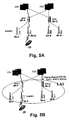
- an idle paging scenario is described in an UTRAN environment with reference to Figs. 5A to 5D , wherein a UE 17 having a connection to a first core network CN1 and being in an idle mode towards a second core network CN 2 is paged from the second core network CN 2.
- a first and a second Node B 20-1, 20-2 having a BTS functionality in the UTRAN environment are connected via a first RNC 50-1 to the first and second core networks CN1, CN2.
- a third and a fourth Node B 20-3, 20-4 also having a BTS functionality in the UTRAN environment are connected via a second RNC 50-2 to the first and second core networks CN1, CN2.
- the UE 17 has a connection established via the second Node B 20-2 and the first RNC 50-1 to the first core network CN 1.
- the second core network CN2 issues an idle mode paging request, including an identification UE-id of the UE 17 and an indication that the location area LA1 is covered by both the first and second RNC 50-1, 50-2.
- the second core network CN2 may select any RNC in the location area LA1 as a target for the paging message. It does not know that the UE 17 has an existing connection in the first RNC 50-1. In the present example, the second core network CN2 selects the second RNC 50-2.
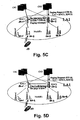
- the selected second RNC 50-2 checks whether any other RNC in the location area LA1 has a connection established for the concerned UE 17.
- the second RNC 50-2 may issue a request based on a mapping information stored at the second RNC 50-2 to the concerned other RNCs asking whether the other RNCs in the location area LA1 have this UE 17 registered as connected and including the identification UE-id and the paging message.
- the first RNC 50-1 having a connection established for the concerned UE 17 answers to the second RNC 50-2 and continues the paging procedure using the existing dedicated RRC connection.
- the first RNC 50-1 sends a corresponding acknowledgement ("Yes, I will forward the page to him!) to the second RNC 50-2.
- unnecessary paging signallings from the second core network CN2 to the other concerned RNCs in the location area LA1 can be prevented to reduce signalling load.
- the present invention can be applied to any access network structure having a paging function for paging a terminal device from a cellular network.
- the description of the preferred embodiment is only intended to illustrate the present invention. The preferred embodiment may thus be modified within the scope of the attached claims.
Claims (21)
- Funkrufsystem für ein Funkzugangsnetzwerk, welches Zugang zu wenigstens einem Kernnetzwerk bereitstellt, wobei das System eine Netzwerksteuerungseinrichtung aufweist, die ein Funkrufsteuerungsmittel (100, 5-1, 50-2) enthält, welches eingerichtet ist, eine an ein mobiles Endgerät (17) gerichtete Funkrufnachricht zu empfangen, nach bestehenden Verbindungen zum mobilen Endgerät (17) von anderen Netzwerksteuerungseinrichtungen (5, 5-2; 50-1) zu überprüfen und die Funkrufnachricht an die anderen Netzwerksteuerungseinrichtungen (5, 5-2; 50-1) basierend auf einer dem Funkrufsteuerungsmittel (100, 5-1, 50-2) bereitgestellten Funkrufnachricht und auf dem Überprüfungsergebnis zu verteilen, wobei, wenn es eine Verbindung von einer anderen Netzwerksteuerungseinrichtung (5, 5-2; 50-1) besteht, dann die Funkrufnachricht an die andere Netzwerksteuerungseinrichtung (5, 5-2; 50-1) weitergeleitet wird, und anderenfalls die Funkrufe an alle Zellen in einem Orts-/Routing-Bereich verteilt werden oder die anderen Netzwerksteuerungseinrichtungen (5, 5-2; 50-1) aufgefordert werden, auf ihren Zellen funkzurufen.
- System gemäß Anspruch 1, wobei die Funkrufnachricht an ein mobiles Endgerät (17) gerichtet ist, dass sich innerhalb des Bereichs des Funkzugangsnetzwerks befindet.
- System gemäß Anspruch 1 oder 2, wobei das Funkrufsteuerungsmittel (100, 5-1, 50-2) ein Funkrufserver (100), ein vorbestimmter Funkzugangsnetzwerkzugangsserver (5-1), oder eine vorbestimmte Funknetzwerksteuerung (50-2) ist.
- System gemäß Anspruch 3, wobei das Funkrufsteuerungsmittel (100, 5-1, 50-2) Speichermittel zum Speichern einer Echtzeitinformation über mobile Endgeräte mit einer Verbindung zum Funkzugangsnetzwerk aufweist.
- System gemäß Anspruch 4, wobei die Echtzeitinformation eine Identifikationsinformation des Mobilgeräts (17) ist.
- System gemäß Anspruch 5, wobei die Identifikationsinformation eine internationale Mobilteilnehmeridentität ist.
- System gemäß einem der vorhergehenden Ansprüche, wobei die Funkrufnachricht Informationen über einen Ortsbereich, einen Routing-Bereich, eine Zelle und/oder Zellressourcen enthält.
- System gemäß einem der vorhergehenden Ansprüche, wobei das Funkzugangsnetzwerk Zugang zu paketvermittelten und leitungsvermittelten Kernnetzwerken bereitstellt und die Funkrufsteuerungsmittel eingerichtet sind, Funkrufe von beiden Netzwerken zu empfangen.
- System gemäß einem der vorhergehenden Ansprüche, wobei das Funkzugangsnetzwerk ein UTRAN, GERAN und/oder andere Funkzugangsnetzwerke aufweist.
- Paging-Verfahren in einem Funkzugangsnetzwerk, das Zugang zu wenigstens einem Kernnetzwerk (CN; CN1; CN2) bereitstellt, wobei das Verfahren die Schritte aufweist:a) Weiterleiten von an ein mobiles Endgerät (17) gerichteter Funkrufen von einem Kernnetzwerk zu einem Funkrufsteuerungsmittel (100; 5-1; 5-2), das eine Netzwerksteuerungseinrichtung enthält;b) Bereitstellen einer Funkrufnachricht an das Funkrufsteuerungsmittel (100; 5-1; 50-2);c) Bestimmen anderer Netzwerksteuerungseinrichtungen (5; 5-2; 50-1), an welche die Funkrufnachricht weiterzuleiten ist, basierend auf der Funkrufnachricht und auf dem Ergebnis einer durch die Funkrufsteuerungsmittel (100; 5-1, 50-2) erhalten Überprüfung nach bestehenden Verbindungen zum mobilen Endgerät (17) von den anderen Netzwerksteuerungseinrichtungen (5, 5-2; 50-1); undd) Verteilen der Funkrufnachricht vom Funkrufsteuerungsmittel (100; 5-1; 50-2) an die bestimmten anderen Netzwerksteuerungseinrichtungen (5; 5-2; 50-1) basierend auf der Funkrufnachricht und dem Ergebnis einer Überprüfung nach bestehenden Verbindungen, wobei, wenn eine Verbindung von einer anderen Netzwerksteuerungseinrichtung (5, 5-2; 50-2) besteht, dann die Funkrufnachricht an die andere Netzwerksteuerungseinrichtung (5, 5-2; 50-1) weitergeleitet wird, und anderenfalls die Funkrufnachricht an alle Zellen in einen Orts-/Routing-Bereich verteilt werden oder die anderen Netzwerksteuerungseinrichtungen (5, 5-2; 50-1) aufgefordert werden, auf ihren Zellen funkzurufen.
- Verfahren gemäß Anspruch 10, wobei die Funkrufnachricht Informationen über einen Ortsbereich, einem Routing-Bereich, eine Zelle und/oder Zellressourcen enthält.
- Verfahren gemäß Anspruch 10 oder 11, weiter aufweisend die Schritte:a) Speichern einer Identifikationsinformation über ein mobiles mit dem Funkzugangsnetzwerk verbundenes Endgerät in einem Speichermittel durch das Funkrufsteuerungsmittel (100; 5-1; 50-2); undb) Entfernen der Identifikationsinformationen über das mobile Endgerät aus dem Speichermittel, sobald die Verbindung zu dem Funkzugangsnetzwerk des mobilen Endgeräts beendet wird.
- Verfahren gemäß Anspruch 12, wobei das Speichermittel eingerichtet ist, eine Echtzeitabbildung mobiler mit dem Funkzugangsnetzwerk verbundener Endgeräte bereitzustellen.
- Verfahren gemäß Anspruch 12 oder 13, wobei die Informationen eine Identifikationsinformation des mit dem Funkzugangsnetzwerk verbundenen Mobilgeräts aufweist.
- Verfahren gemäß Anspruch 14, wobei die Identifikationsinformation eine internationale Mobilteilnehmeridentität ist.
- Verfahren gemäß einem der vorhergehenden Ansprüche 10 bis 15, wobei das Bestimmen die Schritte aufweist:a) Überprüfen mit wenigstens einer anderen Netzwerksteuerungseinrichtung (50-1) des Funkzugangsnetzwerks, ob andere Netzwerksteuerungseinrichtungen (50-1) eine Verbindung zum mobilen Endgerät (17), das durch den Funkruf adressiert ist, besitzt; undb) Verteilen der Funkrufnachricht an die bestimmte andere Netzwerksteuerungseinrichtung (50-1) basierend auf dem Ergebnis des Überprüfungsschritts.
- Verfahren gemäß einem der vorhergehenden Ansprüche 10 bis 15, wobei das Bestimmen den Schritt aufweist:Überprüfen basierend auf der Funkrufnachricht und dem innerhalb der Funkrufsteuerungsmittel (100) gespeicherten Ergebnis einer Überprüfung nach bestehenden Verbindungen, zu welchem anderen Netzwerksteuerungseinrichtungen (5) die Funkrufnachricht weiterzuleiten ist.
- Verfahren gemäß einem der Ansprüche 10 bis 17, wobei das Funkzugangsnetzwerk Zugang zu paketvermittelten und leitungsvermittelten Kernnetzwerken bereitstellt und das Pagingsteuerungsmittel eingerichtet ist, Funkrufe von beiden Kernnetzwerken zu empfangen.
- Verfahren gemäß einem der Ansprüche 10 bis 18, wobei das Funkzugangsnetzwerk ein UTRAN, GERAN und/oder andere Funkzugangsnetzwerke aufweist.
- Netzwerksteuerungseinrichtung für ein Funkzugangsnetzwerk, das Zugang zu wenigstens einem Kernnetzwerk (CN; CN1; CN2) bereitstellt, wobei die Einrichtung (100; 5-1, 50-2) aufweist:a) Empfangsmittel zum Empfangen einer an ein mobiles Endgerät (17) gerichteten Funkrufnachricht;b) Funkrufsteuerungsmittel zum Durchführen einer Steuerung, um so die Funkrufnachricht an andere Netzwerksteuerungseinrichtungen (5; 5-2; 50-1) basierend auf dem Ergebnis einer Überprüfung nach bestehenden Verbindungen zum mobilen Endgerät von den anderen Netzwerksteuerungseinrichtungen (5; 5-2; 50-1) zu verteilen, wobei, wenn eine Verbindung von einer anderen Netzwerksteuerungseinrichtung (5, 5-2; 50-1) besteht, dann die Funkrufnachricht an die Netzwerksteuerungseinrichtung (5, 5-2; 50-1) weitergeleitet wird, und anderenfalls die Funkrufnachricht an alle Zellen in einen Orts-/Routing-Bereich verteilt wird oder die anderen Netzwerksteuerungseinrichtungen (5, 5-2; 50-1) aufgefordert werden, auf ihren Zellen funkzurufen.
- Einrichtung gemäß Anspruch 20, wobei die Netzwerksteuerungseinrichtung ein Funkrufserver (100) ein Funkzugangsnetzwerkzugangsserver (5-1) oder eine Funknetzwerksteuerung (50-2) ist.
Applications Claiming Priority (3)
| Application Number | Priority Date | Filing Date | Title |
|---|---|---|---|
| DE10105093 | 2001-02-05 | ||
| DE10105093A DE10105093A1 (de) | 2001-02-05 | 2001-02-05 | Paging-Verfahren und -System für ein Funkzugriffsnetz |
| PCT/IB2002/000337 WO2002063912A1 (en) | 2001-02-05 | 2002-02-04 | Paging method and system for a radio access network |
Publications (2)
| Publication Number | Publication Date |
|---|---|
| EP1360864A1 EP1360864A1 (de) | 2003-11-12 |
| EP1360864B1 true EP1360864B1 (de) | 2009-07-15 |
Family
ID=7672869
Family Applications (1)
| Application Number | Title | Priority Date | Filing Date |
|---|---|---|---|
| EP02712129A Expired - Lifetime EP1360864B1 (de) | 2001-02-05 | 2002-02-04 | Paging-verfahren und system für ein funkzugriffsnetzwerk |
Country Status (4)
| Country | Link |
|---|---|
| US (1) | US7471957B2 (de) |
| EP (1) | EP1360864B1 (de) |
| DE (2) | DE10105093A1 (de) |
| WO (1) | WO2002063912A1 (de) |
Families Citing this family (41)
| Publication number | Priority date | Publication date | Assignee | Title |
|---|---|---|---|---|
| US7269425B2 (en) | 2001-09-12 | 2007-09-11 | Telefonaktiebolaget Lm Ericsson (Publ) | Location management system and a paging server in a wireless IP network |
| EP1372349A1 (de) * | 2002-06-11 | 2003-12-17 | Alcatel | Mobilfunkzugangsnetz-Architektur und Funkrufverfahren |
| JP4623918B2 (ja) * | 2002-06-26 | 2011-02-02 | 日本電気株式会社 | 移動通信システム並びにその動作制御方法 |
| CN100493238C (zh) * | 2002-08-16 | 2009-05-27 | 北京三星通信技术研究有限公司 | Mbms点对点信道和点对多点信道的转换方法 |
| KR100827137B1 (ko) * | 2002-08-16 | 2008-05-02 | 삼성전자주식회사 | 이동통신시스템에서의 멀티캐스트 멀티미디어 방송 서비스 제공 방법 |
| WO2004023826A1 (en) * | 2002-08-28 | 2004-03-18 | Interdigital Technology Corporation | Wireless radio resource management system using a finite state machine |
| US7546145B2 (en) * | 2002-10-15 | 2009-06-09 | Nokia Corporation | Method, network node and system for managing interfaces in a distributed radio access network |
| JP4206742B2 (ja) * | 2002-12-12 | 2009-01-14 | 日本電気株式会社 | 無線制御装置及びそれを用いた移動通信システム並びにその動作制御方法 |
| JP3882747B2 (ja) * | 2002-12-12 | 2007-02-21 | 日本電気株式会社 | 無線アクセスネットワーク及びその動作制御方法 |
| JP3972198B2 (ja) * | 2002-12-12 | 2007-09-05 | 日本電気株式会社 | セル情報設定方法、無線アクセスネットワークおよび無線制御装置 |
| JP4092562B2 (ja) * | 2002-12-12 | 2008-05-28 | 日本電気株式会社 | 移動通信システム、端末リソース制御部及び基地局リソース制御部、並びにそれらの制御方法 |
| JP3988043B2 (ja) | 2002-12-12 | 2007-10-10 | 日本電気株式会社 | 無線アクセスネットワークの制御方法および無線アクセスネットワーク |
| KR20040061705A (ko) * | 2002-12-31 | 2004-07-07 | 삼성전자주식회사 | 멀티캐스트 멀티미디어 방송 서비스를 위한 이동통신시스템에서 서비스 개시를 위한 정보 전송 방법 |
| ATE295057T1 (de) * | 2003-03-10 | 2005-05-15 | Cit Alcatel | Verfahren zur leitweglenkung von nachrichten zwischen mobil- und zellkontrollfunktionseinheiten von einem verteilten funkzugangsnetz |
| JP4216115B2 (ja) | 2003-05-07 | 2009-01-28 | 株式会社エヌ・ティ・ティ・ドコモ | 移動通信ネットワークシステム、移動端末機及びページング方法 |
| WO2005006800A1 (ja) * | 2003-07-10 | 2005-01-20 | Mitsubishi Denki Kabushiki Kaisha | ページング制御方法、ページング制御装置および無線アクセスネットワーク |
| KR100964679B1 (ko) * | 2003-08-19 | 2010-06-22 | 엘지전자 주식회사 | 멀티미디어 방송 멀티 캐스트서비스에서 무선자원제어연결 모드 단말을 집계하는 방법 |
| JP2005196602A (ja) * | 2004-01-09 | 2005-07-21 | Hitachi Ltd | 無共有型データベース管理システムにおけるシステム構成変更方法 |
| EP2439990B1 (de) * | 2004-03-04 | 2021-01-06 | Samsung Electronics Co., Ltd. | System und Verfahren zur Steuerung des Betriebszustands einer MAC-Schicht in einem drahtlosen Breitbandzugriffskommunikationssystem |
| KR101128796B1 (ko) | 2004-06-07 | 2012-06-12 | 엘지전자 주식회사 | 광대역 무선 접속 시스템에서 단말의 유휴모드 지원 방법 |
| US7590421B2 (en) | 2004-06-07 | 2009-09-15 | Lg Electronics Inc. | Supporting idle mode of mobile station in wireless access system |
| US7894831B2 (en) | 2004-06-08 | 2011-02-22 | Lg Electronics Inc. | Controlling idle mode of mobile subscriber station in wireless access system |
| FR2873886B1 (fr) * | 2004-07-29 | 2006-09-22 | Cit Alcatel | Procede pour l'apprentissage de configuration de structures de localisation dans un systeme cellulaire de communications mobiles |
| KR100665426B1 (ko) | 2005-01-10 | 2007-01-04 | 삼성전자주식회사 | 통신 시스템에서 아이들 모드 상태 제어 시스템 및 방법 |
| WO2007027292A2 (en) * | 2005-08-29 | 2007-03-08 | Motorola, Inc. | Managing delivery of information in a wireless communication network |
| US8682357B2 (en) | 2006-05-02 | 2014-03-25 | Intellectual Ventures Holding 81 Llc | Paging in a wireless network |
| CN101128047B (zh) * | 2006-08-15 | 2010-04-14 | 华为技术有限公司 | 实现核心网业务重分配的方法 |
| KR100751620B1 (ko) * | 2006-09-21 | 2007-08-22 | 포스데이타 주식회사 | 휴대 인터넷 서비스를 지원하기 위한 라우터 및 라우팅방법 |
| CN102572786B (zh) * | 2007-01-15 | 2016-01-06 | Lm爱立信电话有限公司 | 用于通信网络中的电路交换业务的方法及设置 |
| US20080227445A1 (en) * | 2007-03-12 | 2008-09-18 | Nokia Corporation | Paging scheme |
| KR20090052784A (ko) * | 2007-11-21 | 2009-05-26 | 엘지전자 주식회사 | 릴레이를 통한 통신 방법 |
| JP2008109709A (ja) * | 2007-12-28 | 2008-05-08 | Nec Corp | 移動通信システム |
| EP2169641B1 (de) * | 2008-02-22 | 2019-04-10 | Hill-Rom Services, Inc. | Anzeigevorrichtung für Kommunikationssystem im Gesundheitswesen |
| US9198157B2 (en) | 2009-05-08 | 2015-11-24 | Qualcomm Incorporated | Paging for local IP access packets |
| US8611277B2 (en) * | 2009-06-22 | 2013-12-17 | Motorola Mobility Llc | Reselection in a wireless communication system |
| US8638711B2 (en) * | 2009-08-11 | 2014-01-28 | Qualcomm Incorporated | Systems and methods of maintaining core network status during serving radio network subsystem relocation |
| EP2323436A1 (de) * | 2009-11-16 | 2011-05-18 | Nokia Siemens Networks Oy | Lastneuverteilung mit Kommunikationsnetzwerksteuerung |
| CN102209389B (zh) * | 2010-03-29 | 2014-11-19 | 华为技术有限公司 | 寻呼的方法、装置及系统 |
| KR101296578B1 (ko) | 2013-03-07 | 2013-08-14 | 주식회사 에스엠이씨 | Lte 네트워크를 위한 페이징 노드 장치 및 페이징 방법 |
| US9762306B2 (en) * | 2013-08-08 | 2017-09-12 | Intel IP Corporation | Method, apparatus and system for electrical downtilt adjustment in a multiple input multiple output system |
| CA3057061C (en) * | 2016-03-18 | 2020-09-29 | Parallel Wireless, Inc. | Iugw architecture |
Family Cites Families (11)
| Publication number | Priority date | Publication date | Assignee | Title |
|---|---|---|---|---|
| DE69329209T2 (de) * | 1992-01-10 | 2001-04-05 | Nec Corp | Synchronfunkrufsystem |
| ZA957816B (en) * | 1994-09-30 | 1996-05-31 | Qualcomm Inc | Method and apparatus for providing broadcast messages in a communications network |
| JP2581473B2 (ja) * | 1994-11-22 | 1997-02-12 | 日本電気株式会社 | ページングシステムの交互送信方法および装置 |
| DE69735753T2 (de) * | 1996-06-27 | 2007-05-16 | Ntt Docomo, Inc. | Funkrufsystem |
| US6292667B1 (en) * | 1998-05-05 | 2001-09-18 | Telefonaktiebolaget Lm Ericsson (Publ) | Multicell area paging for cellular telecommunications system |
| CA2343026C (en) | 1998-10-06 | 2007-01-09 | Nokia Networks Oy | Paging control method and apparatus |
| US6285667B1 (en) | 1998-12-02 | 2001-09-04 | Telefonaktiebolaget Lm Ericsson | Page response on existing radio signaling channel |
| WO2000063645A1 (de) * | 1999-04-19 | 2000-10-26 | Leica Geosystems Ag | Indirekte positionsbestimmung mit hilfe eines trackers |
| EP1263171B1 (de) * | 2000-03-08 | 2006-05-24 | Hitachi, Ltd. | Steuerungsgerät und -verfahren für paketbasierte kommunikation |
| US6990089B2 (en) * | 2000-12-12 | 2006-01-24 | Telelec | Methods and systems for routing messages in a radio access network |
| ES2296733T3 (es) * | 2001-02-06 | 2008-05-01 | Nokia Corporation | Sistema de acceso para una red celular. |
-
2001
- 2001-02-05 DE DE10105093A patent/DE10105093A1/de not_active Withdrawn
-
2002
- 2002-02-04 WO PCT/IB2002/000337 patent/WO2002063912A1/en not_active Application Discontinuation
- 2002-02-04 US US10/470,945 patent/US7471957B2/en not_active Expired - Fee Related
- 2002-02-04 EP EP02712129A patent/EP1360864B1/de not_active Expired - Lifetime
- 2002-02-04 DE DE60232952T patent/DE60232952D1/de not_active Expired - Lifetime
Also Published As
| Publication number | Publication date |
|---|---|
| US20040102200A1 (en) | 2004-05-27 |
| DE10105093A1 (de) | 2002-08-08 |
| DE60232952D1 (de) | 2009-08-27 |
| US7471957B2 (en) | 2008-12-30 |
| EP1360864A1 (de) | 2003-11-12 |
| WO2002063912A1 (en) | 2002-08-15 |
Similar Documents
| Publication | Publication Date | Title |
|---|---|---|
| EP1360864B1 (de) | Paging-verfahren und system für ein funkzugriffsnetzwerk | |
| JP3908763B2 (ja) | MBMSにおけるポイント対ポイント(PtP)チャンネルとポイント対マルチポイント(PtM)チャンネルの変更方法 | |
| JP4523172B2 (ja) | 移動端末及び無線アクセスネットワーク内のエンティティ間における情報伝送方法及び装置 | |
| US7254392B2 (en) | Intersystem handover with modified parameters | |
| JP3917427B2 (ja) | 通信システムにおける接続 | |
| KR101062076B1 (ko) | 모든 액세스 지점에 대해 단일 식별자를 사용하는 인가되지않은 무선 네트워크 및 셀룰러 네트워크 사이의 핸드오버 | |
| JP4268634B2 (ja) | ワイヤレス通信システムにおいてtddとfddとの間でのリソース割り当てを統合する方法及びシステム | |
| EP1834499B1 (de) | Verfahren und system zur dienstzugangsregelung in gemeinsam benutzten netzwerken | |
| US7242933B1 (en) | Relocation in a communication system | |
| US20030076803A1 (en) | Reconfigurable wireless communication access system and method | |
| US7983676B2 (en) | Inter-system handover | |
| KR20010110656A (ko) | 식별자 할당 방법 | |
| CN101005692A (zh) | 减少终端在lte和3g接入技术间切换的信令的方法 | |
| JP2013123243A (ja) | 電気通信システム及び電気通信方法 | |
| JP2012522437A (ja) | 最小限のパケット損失でwcdma移動局を移動させる装置及び方法 | |
| EP1439724A1 (de) | Mobilkommunikationssystem | |
| KR20010001928A (ko) | 패킷 이동 통신망의 핸드 오버 수행 방법 | |
| EP1260112B1 (de) | Zwischensystem-weiterreichen mit geänderten parameter | |
| GB2371179A (en) | Cell updates in a UMTS terrestrial radio access network | |
| JP4316813B2 (ja) | セルラー通信システムにおける移動通信交換局シグナリングアドレスを決定する方法と装置 | |
| US6804533B1 (en) | Relocation of communication services | |
| JP2004523169A (ja) | ネットワークへの移動要素の接続を管理する方法及びシステム | |
| KR100493446B1 (ko) | 이동통신시스템의 올 아이피(all ip) 망 운용 시스템및 운용방법 | |
| EP1290848B1 (de) | Ip-adresszuweisung in einem mobilen telekommunikationsnetzwerk | |
| GB2369002A (en) | Mobility management in a UMTS network |
Legal Events
| Date | Code | Title | Description |
|---|---|---|---|
| PUAI | Public reference made under article 153(3) epc to a published international application that has entered the european phase |
Free format text: ORIGINAL CODE: 0009012 |
|
| 17P | Request for examination filed |
Effective date: 20030905 |
|
| AK | Designated contracting states |
Kind code of ref document: A1 Designated state(s): AT BE CH CY DE DK ES FI FR GB GR IE IT LI LU MC NL PT SE TR |
|
| AX | Request for extension of the european patent |
Extension state: AL LT LV MK RO SI |
|
| 17Q | First examination report despatched |
Effective date: 20061026 |
|
| GRAP | Despatch of communication of intention to grant a patent |
Free format text: ORIGINAL CODE: EPIDOSNIGR1 |
|
| GRAS | Grant fee paid |
Free format text: ORIGINAL CODE: EPIDOSNIGR3 |
|
| GRAA | (expected) grant |
Free format text: ORIGINAL CODE: 0009210 |
|
| AK | Designated contracting states |
Kind code of ref document: B1 Designated state(s): AT BE CH CY DE DK ES FI FR GB GR IE IT LI LU MC NL PT SE TR |
|
| REG | Reference to a national code |
Ref country code: GB Ref legal event code: FG4D Ref country code: CH Ref legal event code: EP |
|
| REG | Reference to a national code |
Ref country code: IE Ref legal event code: FG4D |
|
| REF | Corresponds to: |
Ref document number: 60232952 Country of ref document: DE Date of ref document: 20090827 Kind code of ref document: P |
|
| NLV1 | Nl: lapsed or annulled due to failure to fulfill the requirements of art. 29p and 29m of the patents act | ||
| PG25 | Lapsed in a contracting state [announced via postgrant information from national office to epo] |
Ref country code: SE Free format text: LAPSE BECAUSE OF FAILURE TO SUBMIT A TRANSLATION OF THE DESCRIPTION OR TO PAY THE FEE WITHIN THE PRESCRIBED TIME-LIMIT Effective date: 20090715 Ref country code: FI Free format text: LAPSE BECAUSE OF FAILURE TO SUBMIT A TRANSLATION OF THE DESCRIPTION OR TO PAY THE FEE WITHIN THE PRESCRIBED TIME-LIMIT Effective date: 20090715 Ref country code: ES Free format text: LAPSE BECAUSE OF FAILURE TO SUBMIT A TRANSLATION OF THE DESCRIPTION OR TO PAY THE FEE WITHIN THE PRESCRIBED TIME-LIMIT Effective date: 20091026 Ref country code: AT Free format text: LAPSE BECAUSE OF FAILURE TO SUBMIT A TRANSLATION OF THE DESCRIPTION OR TO PAY THE FEE WITHIN THE PRESCRIBED TIME-LIMIT Effective date: 20090715 |
|
| PG25 | Lapsed in a contracting state [announced via postgrant information from national office to epo] |
Ref country code: NL Free format text: LAPSE BECAUSE OF FAILURE TO SUBMIT A TRANSLATION OF THE DESCRIPTION OR TO PAY THE FEE WITHIN THE PRESCRIBED TIME-LIMIT Effective date: 20090715 |
|
| PG25 | Lapsed in a contracting state [announced via postgrant information from national office to epo] |
Ref country code: PT Free format text: LAPSE BECAUSE OF FAILURE TO SUBMIT A TRANSLATION OF THE DESCRIPTION OR TO PAY THE FEE WITHIN THE PRESCRIBED TIME-LIMIT Effective date: 20091115 |
|
| PG25 | Lapsed in a contracting state [announced via postgrant information from national office to epo] |
Ref country code: DK Free format text: LAPSE BECAUSE OF FAILURE TO SUBMIT A TRANSLATION OF THE DESCRIPTION OR TO PAY THE FEE WITHIN THE PRESCRIBED TIME-LIMIT Effective date: 20090715 |
|
| PLBE | No opposition filed within time limit |
Free format text: ORIGINAL CODE: 0009261 |
|
| STAA | Information on the status of an ep patent application or granted ep patent |
Free format text: STATUS: NO OPPOSITION FILED WITHIN TIME LIMIT |
|
| PG25 | Lapsed in a contracting state [announced via postgrant information from national office to epo] |
Ref country code: BE Free format text: LAPSE BECAUSE OF FAILURE TO SUBMIT A TRANSLATION OF THE DESCRIPTION OR TO PAY THE FEE WITHIN THE PRESCRIBED TIME-LIMIT Effective date: 20090715 |
|
| 26N | No opposition filed |
Effective date: 20100416 |
|
| PGFP | Annual fee paid to national office [announced via postgrant information from national office to epo] |
Ref country code: GB Payment date: 20100202 Year of fee payment: 9 Ref country code: DE Payment date: 20100211 Year of fee payment: 9 |
|
| REG | Reference to a national code |
Ref country code: CH Ref legal event code: PL |
|
| PG25 | Lapsed in a contracting state [announced via postgrant information from national office to epo] |
Ref country code: MC Free format text: LAPSE BECAUSE OF NON-PAYMENT OF DUE FEES Effective date: 20100301 Ref country code: LI Free format text: LAPSE BECAUSE OF NON-PAYMENT OF DUE FEES Effective date: 20100228 Ref country code: GR Free format text: LAPSE BECAUSE OF FAILURE TO SUBMIT A TRANSLATION OF THE DESCRIPTION OR TO PAY THE FEE WITHIN THE PRESCRIBED TIME-LIMIT Effective date: 20091016 Ref country code: CH Free format text: LAPSE BECAUSE OF NON-PAYMENT OF DUE FEES Effective date: 20100228 |
|
| REG | Reference to a national code |
Ref country code: FR Ref legal event code: ST Effective date: 20101029 |
|
| PG25 | Lapsed in a contracting state [announced via postgrant information from national office to epo] |
Ref country code: IE Free format text: LAPSE BECAUSE OF NON-PAYMENT OF DUE FEES Effective date: 20100204 Ref country code: FR Free format text: LAPSE BECAUSE OF NON-PAYMENT OF DUE FEES Effective date: 20100301 |
|
| PG25 | Lapsed in a contracting state [announced via postgrant information from national office to epo] |
Ref country code: IT Free format text: LAPSE BECAUSE OF FAILURE TO SUBMIT A TRANSLATION OF THE DESCRIPTION OR TO PAY THE FEE WITHIN THE PRESCRIBED TIME-LIMIT Effective date: 20090715 |
|
| GBPC | Gb: european patent ceased through non-payment of renewal fee |
Effective date: 20110204 |
|
| REG | Reference to a national code |
Ref country code: DE Ref legal event code: R119 Ref document number: 60232952 Country of ref document: DE Effective date: 20110901 |
|
| PG25 | Lapsed in a contracting state [announced via postgrant information from national office to epo] |
Ref country code: GB Free format text: LAPSE BECAUSE OF NON-PAYMENT OF DUE FEES Effective date: 20110204 |
|
| PG25 | Lapsed in a contracting state [announced via postgrant information from national office to epo] |
Ref country code: CY Free format text: LAPSE BECAUSE OF FAILURE TO SUBMIT A TRANSLATION OF THE DESCRIPTION OR TO PAY THE FEE WITHIN THE PRESCRIBED TIME-LIMIT Effective date: 20090715 |
|
| PG25 | Lapsed in a contracting state [announced via postgrant information from national office to epo] |
Ref country code: LU Free format text: LAPSE BECAUSE OF NON-PAYMENT OF DUE FEES Effective date: 20100204 |
|
| PG25 | Lapsed in a contracting state [announced via postgrant information from national office to epo] |
Ref country code: TR Free format text: LAPSE BECAUSE OF FAILURE TO SUBMIT A TRANSLATION OF THE DESCRIPTION OR TO PAY THE FEE WITHIN THE PRESCRIBED TIME-LIMIT Effective date: 20090715 |
|
| PG25 | Lapsed in a contracting state [announced via postgrant information from national office to epo] |
Ref country code: DE Free format text: LAPSE BECAUSE OF NON-PAYMENT OF DUE FEES Effective date: 20110901 |