EP1359336A1 - Véhicule avec procédé de régulation à faibles vitesses - Google Patents
Véhicule avec procédé de régulation à faibles vitesses Download PDFInfo
- Publication number
- EP1359336A1 EP1359336A1 EP03007298A EP03007298A EP1359336A1 EP 1359336 A1 EP1359336 A1 EP 1359336A1 EP 03007298 A EP03007298 A EP 03007298A EP 03007298 A EP03007298 A EP 03007298A EP 1359336 A1 EP1359336 A1 EP 1359336A1
- Authority
- EP
- European Patent Office
- Prior art keywords
- motor vehicle
- mode
- torque
- transmission
- creep
- Prior art date
- Legal status (The legal status is an assumption and is not a legal conclusion. Google has not performed a legal analysis and makes no representation as to the accuracy of the status listed.)
- Granted
Links
Images


Classifications
-
- B—PERFORMING OPERATIONS; TRANSPORTING
- B60—VEHICLES IN GENERAL
- B60W—CONJOINT CONTROL OF VEHICLE SUB-UNITS OF DIFFERENT TYPE OR DIFFERENT FUNCTION; CONTROL SYSTEMS SPECIALLY ADAPTED FOR HYBRID VEHICLES; ROAD VEHICLE DRIVE CONTROL SYSTEMS FOR PURPOSES NOT RELATED TO THE CONTROL OF A PARTICULAR SUB-UNIT
- B60W30/00—Purposes of road vehicle drive control systems not related to the control of a particular sub-unit, e.g. of systems using conjoint control of vehicle sub-units, or advanced driver assistance systems for ensuring comfort, stability and safety or drive control systems for propelling or retarding the vehicle
- B60W30/18—Propelling the vehicle
- B60W30/18009—Propelling the vehicle related to particular drive situations
- B60W30/18063—Creeping
-
- F—MECHANICAL ENGINEERING; LIGHTING; HEATING; WEAPONS; BLASTING
- F16—ENGINEERING ELEMENTS AND UNITS; GENERAL MEASURES FOR PRODUCING AND MAINTAINING EFFECTIVE FUNCTIONING OF MACHINES OR INSTALLATIONS; THERMAL INSULATION IN GENERAL
- F16D—COUPLINGS FOR TRANSMITTING ROTATION; CLUTCHES; BRAKES
- F16D48/00—External control of clutches
- F16D48/06—Control by electric or electronic means, e.g. of fluid pressure
-
- B—PERFORMING OPERATIONS; TRANSPORTING
- B60—VEHICLES IN GENERAL
- B60W—CONJOINT CONTROL OF VEHICLE SUB-UNITS OF DIFFERENT TYPE OR DIFFERENT FUNCTION; CONTROL SYSTEMS SPECIALLY ADAPTED FOR HYBRID VEHICLES; ROAD VEHICLE DRIVE CONTROL SYSTEMS FOR PURPOSES NOT RELATED TO THE CONTROL OF A PARTICULAR SUB-UNIT
- B60W2540/00—Input parameters relating to occupants
- B60W2540/10—Accelerator pedal position
-
- B—PERFORMING OPERATIONS; TRANSPORTING
- B60—VEHICLES IN GENERAL
- B60W—CONJOINT CONTROL OF VEHICLE SUB-UNITS OF DIFFERENT TYPE OR DIFFERENT FUNCTION; CONTROL SYSTEMS SPECIALLY ADAPTED FOR HYBRID VEHICLES; ROAD VEHICLE DRIVE CONTROL SYSTEMS FOR PURPOSES NOT RELATED TO THE CONTROL OF A PARTICULAR SUB-UNIT
- B60W2540/00—Input parameters relating to occupants
- B60W2540/12—Brake pedal position
-
- F—MECHANICAL ENGINEERING; LIGHTING; HEATING; WEAPONS; BLASTING
- F16—ENGINEERING ELEMENTS AND UNITS; GENERAL MEASURES FOR PRODUCING AND MAINTAINING EFFECTIVE FUNCTIONING OF MACHINES OR INSTALLATIONS; THERMAL INSULATION IN GENERAL
- F16D—COUPLINGS FOR TRANSMITTING ROTATION; CLUTCHES; BRAKES
- F16D2500/00—External control of clutches by electric or electronic means
- F16D2500/10—System to be controlled
- F16D2500/104—Clutch
- F16D2500/10406—Clutch position
- F16D2500/10412—Transmission line of a vehicle
-
- F—MECHANICAL ENGINEERING; LIGHTING; HEATING; WEAPONS; BLASTING
- F16—ENGINEERING ELEMENTS AND UNITS; GENERAL MEASURES FOR PRODUCING AND MAINTAINING EFFECTIVE FUNCTIONING OF MACHINES OR INSTALLATIONS; THERMAL INSULATION IN GENERAL
- F16D—COUPLINGS FOR TRANSMITTING ROTATION; CLUTCHES; BRAKES
- F16D2500/00—External control of clutches by electric or electronic means
- F16D2500/30—Signal inputs
- F16D2500/31—Signal inputs from the vehicle
- F16D2500/3108—Vehicle speed
- F16D2500/3111—Standing still, i.e. signal detecting when the vehicle is standing still or bellow a certain limit speed
-
- F—MECHANICAL ENGINEERING; LIGHTING; HEATING; WEAPONS; BLASTING
- F16—ENGINEERING ELEMENTS AND UNITS; GENERAL MEASURES FOR PRODUCING AND MAINTAINING EFFECTIVE FUNCTIONING OF MACHINES OR INSTALLATIONS; THERMAL INSULATION IN GENERAL
- F16D—COUPLINGS FOR TRANSMITTING ROTATION; CLUTCHES; BRAKES
- F16D2500/00—External control of clutches by electric or electronic means
- F16D2500/30—Signal inputs
- F16D2500/314—Signal inputs from the user
- F16D2500/31406—Signal inputs from the user input from pedals
- F16D2500/3144—Accelerator pedal position
- F16D2500/31453—Accelerator pedal position threshold, e.g. switch
-
- F—MECHANICAL ENGINEERING; LIGHTING; HEATING; WEAPONS; BLASTING
- F16—ENGINEERING ELEMENTS AND UNITS; GENERAL MEASURES FOR PRODUCING AND MAINTAINING EFFECTIVE FUNCTIONING OF MACHINES OR INSTALLATIONS; THERMAL INSULATION IN GENERAL
- F16D—COUPLINGS FOR TRANSMITTING ROTATION; CLUTCHES; BRAKES
- F16D2500/00—External control of clutches by electric or electronic means
- F16D2500/50—Problem to be solved by the control system
- F16D2500/502—Relating the clutch
- F16D2500/50206—Creep control
- F16D2500/50209—Activation of the creep control operation
- F16D2500/50212—Accelerator pedal
-
- F—MECHANICAL ENGINEERING; LIGHTING; HEATING; WEAPONS; BLASTING
- F16—ENGINEERING ELEMENTS AND UNITS; GENERAL MEASURES FOR PRODUCING AND MAINTAINING EFFECTIVE FUNCTIONING OF MACHINES OR INSTALLATIONS; THERMAL INSULATION IN GENERAL
- F16D—COUPLINGS FOR TRANSMITTING ROTATION; CLUTCHES; BRAKES
- F16D2500/00—External control of clutches by electric or electronic means
- F16D2500/50—Problem to be solved by the control system
- F16D2500/508—Relating driving conditions
- F16D2500/50858—Selecting a Mode of operation
-
- F—MECHANICAL ENGINEERING; LIGHTING; HEATING; WEAPONS; BLASTING
- F16—ENGINEERING ELEMENTS AND UNITS; GENERAL MEASURES FOR PRODUCING AND MAINTAINING EFFECTIVE FUNCTIONING OF MACHINES OR INSTALLATIONS; THERMAL INSULATION IN GENERAL
- F16D—COUPLINGS FOR TRANSMITTING ROTATION; CLUTCHES; BRAKES
- F16D2500/00—External control of clutches by electric or electronic means
- F16D2500/50—Problem to be solved by the control system
- F16D2500/51—Relating safety
- F16D2500/5114—Failsafe
Definitions
- the invention relates to a motor vehicle with a drive unit, a Gearbox and a torque transmission device between the drive unit and the transmission having the drive train, which in at least a crawl mode is operable in which a predetermined or adjustable or from operating parameters of the drive train components or / and other motor vehicle components resulting creep torque transferable to driven or drivable wheels of the motor vehicle is or is transmitted and a method for operating such Motor vehicle in which the drive train and / or the drive unit or / and the torque transmission device or / and that Gearbox and / or a / the braking device of the motor vehicle for activation or deactivation of a crawl mode and / or for setting of a creep torque is controlled.
- System-related creep is from automatic vehicles with torque converters known and can not be switched off conventionally become.
- motor vehicles without an automatic transmission for example Vehicles with an automated manual transmission can such creep is simulated by appropriate functionalities become.
- DE 100 16 582 A1 proposes a separate actuating element, below the mediation of the creep can be activated.
- DE 196 39 322 A1 it is known to have an automatically controlled motor vehicle Provide clutch based on at least one driver's side Actuation of a vehicle brake, actuation of a driver Control element of the engine and based on an on state a driving or gear stage is adjustable to a creep torque, wherein the clutch set to the creep torque with permanent actuation the vehicle brake is opened after a predetermined delay time, or / and the creep torque is slowly reduced when the brake is actuated or / and when the vehicle brake is actuated compared to the creep torque reduced clutch torque is set.
- the driver cannot decide whether he is fundamentally wants to have a crawl functionality in a given situation or not.
- the vehicle also crawls in what the driver finds inappropriate Moments. This applies in particular to system-related creep in vehicles with an automatic transmission and associated Torque converter.
- the invention proposes based on the objective that the driver should be able to decide for himself whether to use a Crawling wishes and accepts, or whether he activates or deactivates it wants, according to one aspect, that the crawl mode is defined by a manual actuation of a driver control element to be actuated by the driver, in particular accelerator pedal, the motor vehicle can be activated.
- the need to actively activate or deactivate the creep mode can by some drivers at least for some situations also be perceived as annoying.
- the invention looks up another aspect that at least one basic vehicle setting is provided or - preferably - is adjustable, according to which for at least a vehicle situation predetermines the activation of the creep mode is or after not being activated for at least one vehicle situation the creep mode is specified.
- the basic vehicle setting the activation of the Creep mode and the non-activated creep mode adjustable is. In this case, the driver is even in control of the basic vehicle settings.
- the basic vehicle setting inevitably after the occurrence of at least one predetermined Vehicle condition or after the appearance of one of several Vehicle states or / and after a defined change in the vehicle state is effective.
- the basic vehicle setting inevitably after a vehicle start and / or after a transition Driving-stopping or driving-coasting may be effective.
- the motor vehicle is further developed that the activation depending on at least one other operating parameter of the motor vehicle, preferably a current speed of the motor vehicle. For example, it usually does be useful if the crawl mode only when the vehicle is stationary or if the current speed is below a threshold value of the motor vehicle can be activated.
- the crawl mode can be defined by manual operation of the Braking device permanently, namely until the reactivation of the Creep mode through the defined manual actuation of the drive control element or / and according to an effective one being activated Creep mode specifying basic vehicle setting, can be deactivated his.
- Such a design of the motor vehicle or such, possibly selectable basic setting of the motor vehicle is particularly in With regard to a high level of security against incorrect operation and just in case of driving the motor vehicle by someone less familiar with it Driver advantageous.
- the brake device mentioned can be a service brake device act of the motor vehicle.
- the Braking device by means of a brake control element, in particular a brake pedal, be manually operable, by means of the brake control member the creep torque can be reduced and / or the creep mode can be deactivated is.
- the transmission can be an automatic transmission, which, as is conventional, a torque converter device or a starting clutch device, for example wet-running starting clutch device, be assigned as a torque transmission device can.
- the automatic transmission can be an automatic one Multi-step transmission or a continuously variable automatic transmission, act for example with a steel sliding link belt or the like. in the In the case of a torque converter device that is running while the drive unit (such as an internal combustion engine or an internal combustion engine) inherently Transmits creep torque, can deactivate the creep mode Creep torque by corresponding actuation of a / the braking device be braked.
- the mentioned friction clutch device can be used as a single clutch device be formed, the one of a transmission input shaft of the Transmission associated clutch arrangement has.
- the friction clutch device it can also be a so-called double or multiple coupling device act, at least two each assigned to a separate transmission input shaft of the transmission, independently has mutually actuatable clutch assemblies.
- the transmission can be a so-called double clutch transmission or power shift transmission.
- the torque transmission device a preferably wet starting clutch device having.
- the transmission moment can do this in the crawl mode of the torque transmission device be transferable moment.
- the creep torque can the setting of a braking torque of a / the braking device of the motor vehicle based, for example, on the way that while running Drive unit transmitted by the torque transmission device Partial drive torque or transmission torque (for setting the Creep torque) or complete (to deactivate the creep mode) is braked.
- the control unit By comparing the speed of the speed sensor 44 on the one hand and the Speed of the speed sensor 40 or 42 on the other hand, the control unit a slip state of the clutch arrangement 26 or the clutch arrangement 28 determine.
- the control unit 36 controls a power actuator of the engine 12 to the power output by the engine or adjust the torque given by the engine.
- crankshaft starter generator 50 is shown, the one on Motor 12 arranged stator assembly and one on the input side of the Double clutch 24 arranged rotor assembly.
- the crankshaft starter generator 50 is activated by the control unit 36, in particular to start the engine 12.
- the powershift transmission which can also be called a double clutch transmission 18 it should also be noted that it is preferably a fully synchronized one Gearbox acts with a corresponding synchronizing device 52.
- the synchronization device 52 does not need to be a central one Act synchronizer for the whole transmission.
- the synchronizer can also from conventional synchronizers, such as in the form of synchronizer rings.
- An output shaft of the transmission is designated 54.
- the transmission is preferably fully automated by means of a correspondingly controllable by the control unit 36 Actuator 56 actuated.
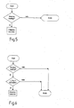
- the crawl mode is below Mediation of the accelerator or accelerator pedal 46 can be activated. It can be provided be that the activation of the creep mode by means of the accelerator pedal only when the vehicle is stationary or at a speed threshold vehicle speed falling below (v_Fzg; see Fig. 4) is possible, provided that the accelerator pedal beforehand was not operated. Activation can be done, for example, by a light, short (e.g. ⁇ 500 ms) or double tap on the accelerator pedal take place within a predetermined time interval.
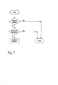
- the creep is by means of the brake pedal only when the vehicle is at a standstill and / or on the Detection of a relatively strong actuation pulse on the brake pedal disabled.
- the Deactivation of the crawl functionality from the duration of the brake pedal actuation depend so that e.g. B. a short tap on the brake pedal Creep disabled.
- the control unit must use the type of brake application (e.g. duration and / or strength of the Brake actuation) and possibly depending on other parameters, such as the current vehicle speed, decide whether the Creep functionality should be deactivated and whether the creep mode actuation of the vehicle brake is present.
- the driver regarding the activation or A corresponding basic vehicle setting is not activated for the creep functionality can choose which in the event of a vehicle standstill Effect comes, with the vehicle stopped either a standstill after starting the vehicle or after a standstill a transition driving / stopping or coasting or - alternatively - for any vehicle standstill.
- a relevant vehicle standstill effective vehicle basic setting specifies that creep condition, in which the driver of the motor vehicle when the vehicle was last stopped has moved.
- the crawl mode is either basically activated or is basically deactivated.
- Various variants are conceivable, e.g. B. that always make the same default immediately after starting a vehicle is activated (either creep activated or creep deactivated), and that at every further vehicle standstill a basic setting is effective, the last driver setting regarding deactivation or non-activation the crawl mode.
- the basic setting of the vehicle regarding activation and non-activation the crawl mode especially the requirement that the Creep is activated in principle or is not activated in principle for example via a display using a multi-function actuator or be selected using a separate actuator.
- One design option is, for example, that in the case of a Actuation of a parking brake (in particular hand brake) of the motor vehicle the crawl mode is not activated despite actuation of the accelerator pedal is, or, if already activated, deactivated immediately.
- Procedures according to the invention relating to the activation / deactivation Creep functionality can also be achieved with differently designed drive trains as illustrated in FIG. 1 can be used advantageously. So there is already a motor vehicle drive train with an automatic transmission 18 and a torque converter 60 connected upstream thereof has been addressed (Fig. 2). Transmits while the drive unit 12 is running the torque converter 60 inherently has a creep torque that is conventional in a forward drive (D) state or a reverse drive (R) state of the transmission cannot be turned off unless the driver the service brake system of the motor vehicle operated accordingly.
- D forward drive
- R reverse drive
- you can activate and deactivate creep according to the Proposals for invention made here also with such a drive train provide that, for example, the control unit 36 a Brake unit 62 of the motor vehicle actuated in such a way that it is mediated the vehicle brakes 66 assigned to the wheels 64 the creep torque is braked to zero.
- Another option is a corresponding one Switching the transmission states, for example between the D state or the R state on the one hand and the neutral (N) state on the other hand, depending on the actuation of the accelerator pedal (activation crawling) and brake pedal (disabling crawling, if necessary setting the creep torque), with appropriate selectable basic vehicle settings can be provided.
- the proposed methods for activating / deactivating a creep functionality are therefore in principle in every motor vehicle drive train, at which a creeping moment occurs or is adjustable, so applicable for example in any automated manual transmission with at least one Coupling for (automated) double or multiple coupling devices with corresponding gear, with (step) automatic transmissions with and without torque converter.
- a torque converter for example, a (possibly wet-running) starting clutch can be provided, where a creep is not due to the system, but by appropriate ones Actuation a creep torque is adjustable.
- the invention relates, inter alia, to a motor vehicle with a drive unit, a transmission and a torque transmission device between the drive unit and the transmission Powertrain that can be operated in at least one crawl mode is in which a predetermined or adjustable or from operating parameters the powertrain components and / or other motor vehicle components resulting creep torque to driven or drivable wheels of the motor vehicle is transferable or is transferred.
- the crawl mode be defined by a manual Actuation of a driving control element to be actuated on the driving side, in particular Accelerator pedal, the motor vehicle can be activated and / or that at least one Basic vehicle setting is provided or - preferably - adjustable is according to which the activated mode of the creep mode is specified or according to which the crawl mode is not activated.
Applications Claiming Priority (2)
| Application Number | Priority Date | Filing Date | Title |
|---|---|---|---|
| DE10219420A DE10219420A1 (de) | 2002-05-02 | 2002-05-02 | Kraftfahrzeug mit Kriechfunktion |
| DE10219420 | 2002-05-02 |
Publications (2)
| Publication Number | Publication Date |
|---|---|
| EP1359336A1 true EP1359336A1 (fr) | 2003-11-05 |
| EP1359336B1 EP1359336B1 (fr) | 2009-03-18 |
Family
ID=28798946
Family Applications (1)
| Application Number | Title | Priority Date | Filing Date |
|---|---|---|---|
| EP03007298A Expired - Lifetime EP1359336B1 (fr) | 2002-05-02 | 2003-04-01 | Véhicule avec procédé de régulation à faibles vitesses |
Country Status (2)
| Country | Link |
|---|---|
| EP (1) | EP1359336B1 (fr) |
| DE (2) | DE10219420A1 (fr) |
Cited By (11)
| Publication number | Priority date | Publication date | Assignee | Title |
|---|---|---|---|---|
| EP1630055A1 (fr) * | 2004-08-14 | 2006-03-01 | LuK Lamellen und Kupplungsbau Beteiligungs KG | Véhicule automobile avec un système de freinage et procédé d'actionnement d'un système de freinage |
| WO2006119865A1 (fr) * | 2005-05-10 | 2006-11-16 | Zf Friedrichschafen Ag | Procede pour activer ou desactiver un mode manoeuvre d'un vehicule automobile |
| WO2007030042A1 (fr) * | 2005-09-08 | 2007-03-15 | Volvo Lastvagnar Ab | Procede et dispositif de commande d'un embrayage dans un vehicule |
| WO2007139482A1 (fr) * | 2006-05-26 | 2007-12-06 | Scania Cv Ab (Publ) | Système de commande d'opération |
| WO2009010363A2 (fr) * | 2007-07-14 | 2009-01-22 | Zf Friedrichshafen Ag | Procédé de commande d'un embrayage automatique |
| EP2085282A1 (fr) * | 2008-01-29 | 2009-08-05 | KNORR-BREMSE Systeme für Nutzfahrzeuge GmbH | Procédé de freinage d'un véhicule |
| EP2159118A1 (fr) * | 2008-08-26 | 2010-03-03 | Peugeot Citroën Automobiles Sa | Procédé et dispositif de contrôle commandé de marche d'un véhicule |
| DE102009055832A1 (de) * | 2009-11-26 | 2011-06-01 | GM Global Technology Operations LLC, ( n. d. Ges. d. Staates Delaware ), Detroit | Verfahren zur Steuerung einer Kupplungsvorrichtung und elektronisch gesteuerte Reibungskupplung |
| CN105246757A (zh) * | 2013-05-24 | 2016-01-13 | 标致·雪铁龙汽车公司 | 根据车辆速度和制动来控制车辆的蠕行模式的方法和装置 |
| DE102017219675A1 (de) * | 2017-11-06 | 2019-05-09 | Audi Ag | Verfahren zum Betrieb eines Kraftfahrzeugs und Kraftfahrzeug |
| DE102014110357B4 (de) | 2013-07-26 | 2021-12-23 | GM Global Technology Operations LLC (n. d. Gesetzen des Staates Delaware) | Getriebe mit kriechsteuerungs-interventionsfunktionalität |
Families Citing this family (9)
| Publication number | Priority date | Publication date | Assignee | Title |
|---|---|---|---|---|
| DE102004040158B4 (de) * | 2004-08-19 | 2006-09-07 | Autohaus Hermann Hüwels GmbH & Co.KG | Einrichtung zum Einlegen einer Fahrstufe und zur Kriechverhinderung |
| DE102005046893A1 (de) * | 2005-09-30 | 2007-04-05 | Zf Friedrichshafen Ag | Verfahren zur Steuerung eines automatisierten Lastschaltgetriebes |
| DE102006051230A1 (de) * | 2006-10-31 | 2008-05-08 | Bayerische Motoren Werke Ag | Kraftfahrzeug mit einer Getriebeeinrichtung zur automatischen Einstellung einer Antriebsübersetzung und Verfahren zum Betrieb eines derartigen Kraftfahrzeugs |
| DE102007021019B4 (de) | 2007-05-04 | 2015-12-17 | Bayerische Motoren Werke Aktiengesellschaft | Verfahren zur automatischen Anfahrunterstützung eines Kraftfahrzeugs |
| DE102007043586B4 (de) | 2007-09-13 | 2020-09-03 | Bayerische Motoren Werke Aktiengesellschaft | Verfahren zur Steuerung einer Antriebseinheit eines Hybridfahrzeugs |
| DE102007055722A1 (de) * | 2007-12-06 | 2009-06-10 | Zf Friedrichshafen Ag | Verfahren zur Steuerung eines Kraftfahrzeugs mit automatisierter Kupplung |
| DE102009030605B4 (de) * | 2009-06-26 | 2012-12-06 | Bayerische Motoren Werke Aktiengesellschaft | Verfahren zur Steuerung eines Kraftfahrzeug-Antriebsstranges |
| KR101795130B1 (ko) | 2015-04-16 | 2017-12-01 | 현대자동차주식회사 | 전기 자동차의 크립주행 제어 장치 및 그 방법 |
| DE102018221884A1 (de) * | 2018-12-17 | 2020-06-18 | Zf Friedrichshafen Ag | Verfahren und Steuergerät zum Betreiben eines Antriebsstrangs eines Kraftfahrzeugs |
Citations (20)
| Publication number | Priority date | Publication date | Assignee | Title |
|---|---|---|---|---|
| EP0375162A2 (fr) * | 1988-12-20 | 1990-06-27 | Isuzu Motors Limited | Systemé de commande d'embrayage de véhicule |
| EP0393910A2 (fr) * | 1989-04-12 | 1990-10-24 | Hitachi, Ltd. | Transmission pour véhicule |
| US5378211A (en) * | 1992-12-09 | 1995-01-03 | Eaton Corporation | Clutch mode control logic |
| DE4426260A1 (de) | 1993-08-03 | 1995-02-09 | Luk Getriebe Systeme Gmbh | Kraftfahrzeug |
| EP0731294A2 (fr) * | 1995-03-08 | 1996-09-11 | Eaton Corporation | Mode amélioré facultatif pour vitesse de rampage d'un embrayage automatique et transmission mécanique automatique pour véhicule l'utilisant |
| DE19530613A1 (de) * | 1995-08-21 | 1997-02-27 | Daimler Benz Ag | Steuerung einer automatischen Kupplung |
| DE19639322A1 (de) | 1996-09-25 | 1998-05-28 | Daimler Benz Ag | Automatisch gesteuerte Kupplung |
| DE19807764A1 (de) * | 1997-02-27 | 1998-09-03 | Luk Getriebe Systeme Gmbh | Kraftfahrzeug |
| DE19823284A1 (de) * | 1997-06-06 | 1998-12-10 | Luk Getriebe Systeme Gmbh | Vorrichtung zur Steuerung eines Einrückzustandes einer Kupplung |
| DE19841917A1 (de) * | 1998-09-14 | 1999-12-16 | Mannesmann Sachs Ag | Antriebsanordnung für ein Kraftfahrzeug |
| DE19922694A1 (de) | 1999-05-18 | 2000-11-23 | Zahnradfabrik Friedrichshafen | Verfahren zur Steuerung eines Automatgetriebes eines Kraftfahrzeuges |
| DE10029618A1 (de) | 1999-06-24 | 2001-01-25 | Luk Lamellen & Kupplungsbau | Kupplungsvorrichtung |
| EP1090798A1 (fr) * | 1999-04-23 | 2001-04-11 | Yanmar Diesel Engine Co. Ltd. | Systeme de transmission automobile |
| DE19951106A1 (de) | 1999-10-23 | 2001-04-26 | Zahnradfabrik Friedrichshafen | Verfahren zur Steuerung eines Automatgetriebes |
| EP1101969A1 (fr) * | 1999-11-18 | 2001-05-23 | Ford Global Technologies, Inc. | Stratégie de commande pour une transmission automatique |
| DE19956305A1 (de) | 1999-11-20 | 2001-05-23 | Volkswagen Ag | Verfahren und Vorrichtung zur Steuerung einer automatisierten Kupplung |
| DE10038379A1 (de) | 2000-01-28 | 2001-08-16 | Mitsubishi Electric Corp | Automatikgetriebe vom Gangtyp und Verfahren zum Steuern desselben |
| DE10016582A1 (de) | 2000-04-04 | 2001-10-11 | Zahnradfabrik Friedrichshafen | Rangiermodus bei Fahrzeugen mit automatisierter Kupplung |
| WO2002099302A1 (fr) * | 2001-06-05 | 2002-12-12 | Luk Lamellen Und Kupplungsbau Beteiligungs Kg | Procede de commande et/ou de reglage d'un embrayage automatique et/ou d'une boite de vitesses automatique d'un vehicule |
| WO2002101257A1 (fr) * | 2001-06-13 | 2002-12-19 | Luk Lamellen Und Kupplungsbau Beteiligungs Kg | Procede et systeme pour reguler le comportement de rampement d'un vehicule equipe d'un embrayage automatique |
-
2002
- 2002-05-02 DE DE10219420A patent/DE10219420A1/de not_active Withdrawn
-
2003
- 2003-04-01 EP EP03007298A patent/EP1359336B1/fr not_active Expired - Lifetime
- 2003-04-01 DE DE50311301T patent/DE50311301D1/de not_active Expired - Lifetime
Patent Citations (22)
| Publication number | Priority date | Publication date | Assignee | Title |
|---|---|---|---|---|
| EP0375162A2 (fr) * | 1988-12-20 | 1990-06-27 | Isuzu Motors Limited | Systemé de commande d'embrayage de véhicule |
| EP0393910A2 (fr) * | 1989-04-12 | 1990-10-24 | Hitachi, Ltd. | Transmission pour véhicule |
| US5378211A (en) * | 1992-12-09 | 1995-01-03 | Eaton Corporation | Clutch mode control logic |
| DE4426260A1 (de) | 1993-08-03 | 1995-02-09 | Luk Getriebe Systeme Gmbh | Kraftfahrzeug |
| EP0731294A2 (fr) * | 1995-03-08 | 1996-09-11 | Eaton Corporation | Mode amélioré facultatif pour vitesse de rampage d'un embrayage automatique et transmission mécanique automatique pour véhicule l'utilisant |
| DE19530613C2 (de) | 1995-08-21 | 2001-07-19 | Daimler Chrysler Ag | Steuerung einer automatischen Kupplung |
| DE19530613A1 (de) * | 1995-08-21 | 1997-02-27 | Daimler Benz Ag | Steuerung einer automatischen Kupplung |
| EP0761490A1 (fr) | 1995-08-21 | 1997-03-12 | Mercedes-Benz Ag | Commande d'un embrayage automatique |
| DE19639322A1 (de) | 1996-09-25 | 1998-05-28 | Daimler Benz Ag | Automatisch gesteuerte Kupplung |
| DE19807764A1 (de) * | 1997-02-27 | 1998-09-03 | Luk Getriebe Systeme Gmbh | Kraftfahrzeug |
| DE19823284A1 (de) * | 1997-06-06 | 1998-12-10 | Luk Getriebe Systeme Gmbh | Vorrichtung zur Steuerung eines Einrückzustandes einer Kupplung |
| DE19841917A1 (de) * | 1998-09-14 | 1999-12-16 | Mannesmann Sachs Ag | Antriebsanordnung für ein Kraftfahrzeug |
| EP1090798A1 (fr) * | 1999-04-23 | 2001-04-11 | Yanmar Diesel Engine Co. Ltd. | Systeme de transmission automobile |
| DE19922694A1 (de) | 1999-05-18 | 2000-11-23 | Zahnradfabrik Friedrichshafen | Verfahren zur Steuerung eines Automatgetriebes eines Kraftfahrzeuges |
| DE10029618A1 (de) | 1999-06-24 | 2001-01-25 | Luk Lamellen & Kupplungsbau | Kupplungsvorrichtung |
| DE19951106A1 (de) | 1999-10-23 | 2001-04-26 | Zahnradfabrik Friedrichshafen | Verfahren zur Steuerung eines Automatgetriebes |
| EP1101969A1 (fr) * | 1999-11-18 | 2001-05-23 | Ford Global Technologies, Inc. | Stratégie de commande pour une transmission automatique |
| DE19956305A1 (de) | 1999-11-20 | 2001-05-23 | Volkswagen Ag | Verfahren und Vorrichtung zur Steuerung einer automatisierten Kupplung |
| DE10038379A1 (de) | 2000-01-28 | 2001-08-16 | Mitsubishi Electric Corp | Automatikgetriebe vom Gangtyp und Verfahren zum Steuern desselben |
| DE10016582A1 (de) | 2000-04-04 | 2001-10-11 | Zahnradfabrik Friedrichshafen | Rangiermodus bei Fahrzeugen mit automatisierter Kupplung |
| WO2002099302A1 (fr) * | 2001-06-05 | 2002-12-12 | Luk Lamellen Und Kupplungsbau Beteiligungs Kg | Procede de commande et/ou de reglage d'un embrayage automatique et/ou d'une boite de vitesses automatique d'un vehicule |
| WO2002101257A1 (fr) * | 2001-06-13 | 2002-12-19 | Luk Lamellen Und Kupplungsbau Beteiligungs Kg | Procede et systeme pour reguler le comportement de rampement d'un vehicule equipe d'un embrayage automatique |
Cited By (16)
| Publication number | Priority date | Publication date | Assignee | Title |
|---|---|---|---|---|
| EP1630055A1 (fr) * | 2004-08-14 | 2006-03-01 | LuK Lamellen und Kupplungsbau Beteiligungs KG | Véhicule automobile avec un système de freinage et procédé d'actionnement d'un système de freinage |
| WO2006119865A1 (fr) * | 2005-05-10 | 2006-11-16 | Zf Friedrichschafen Ag | Procede pour activer ou desactiver un mode manoeuvre d'un vehicule automobile |
| WO2007030042A1 (fr) * | 2005-09-08 | 2007-03-15 | Volvo Lastvagnar Ab | Procede et dispositif de commande d'un embrayage dans un vehicule |
| WO2007139482A1 (fr) * | 2006-05-26 | 2007-12-06 | Scania Cv Ab (Publ) | Système de commande d'opération |
| WO2009010363A2 (fr) * | 2007-07-14 | 2009-01-22 | Zf Friedrichshafen Ag | Procédé de commande d'un embrayage automatique |
| WO2009010363A3 (fr) * | 2007-07-14 | 2009-04-02 | Zahnradfabrik Friedrichshafen | Procédé de commande d'un embrayage automatique |
| CN101743409B (zh) * | 2007-07-14 | 2012-11-21 | Zf腓德烈斯哈芬股份公司 | 用于控制自动分离离合器的方法 |
| EP2085282A1 (fr) * | 2008-01-29 | 2009-08-05 | KNORR-BREMSE Systeme für Nutzfahrzeuge GmbH | Procédé de freinage d'un véhicule |
| FR2935330A1 (fr) * | 2008-08-26 | 2010-03-05 | Peugeot Citroen Automobiles Sa | Procede et dispositif de controle commande de marche d'un vehicule. |
| EP2159118A1 (fr) * | 2008-08-26 | 2010-03-03 | Peugeot Citroën Automobiles Sa | Procédé et dispositif de contrôle commandé de marche d'un véhicule |
| DE102009055832A1 (de) * | 2009-11-26 | 2011-06-01 | GM Global Technology Operations LLC, ( n. d. Ges. d. Staates Delaware ), Detroit | Verfahren zur Steuerung einer Kupplungsvorrichtung und elektronisch gesteuerte Reibungskupplung |
| CN105246757A (zh) * | 2013-05-24 | 2016-01-13 | 标致·雪铁龙汽车公司 | 根据车辆速度和制动来控制车辆的蠕行模式的方法和装置 |
| CN105246757B (zh) * | 2013-05-24 | 2018-01-16 | 标致·雪铁龙汽车公司 | 根据车辆速度和制动来控制车辆的蠕行模式的方法和装置 |
| DE102014110357B4 (de) | 2013-07-26 | 2021-12-23 | GM Global Technology Operations LLC (n. d. Gesetzen des Staates Delaware) | Getriebe mit kriechsteuerungs-interventionsfunktionalität |
| DE102017219675A1 (de) * | 2017-11-06 | 2019-05-09 | Audi Ag | Verfahren zum Betrieb eines Kraftfahrzeugs und Kraftfahrzeug |
| US11007879B2 (en) | 2017-11-06 | 2021-05-18 | Audi Ag | Method for operating a motor vehicle and motor vehicle |
Also Published As
| Publication number | Publication date |
|---|---|
| DE10219420A1 (de) | 2003-11-13 |
| DE50311301D1 (de) | 2009-04-30 |
| EP1359336B1 (fr) | 2009-03-18 |
Similar Documents
| Publication | Publication Date | Title |
|---|---|---|
| EP1359336B1 (fr) | Véhicule avec procédé de régulation à faibles vitesses | |
| DE10080639B4 (de) | Kupplungssteuervorrichtung zur automatischen Betätigung einer Kupplung während des Anfahrens | |
| EP2342112B1 (fr) | Procédé pour commander une boîte de vitesses automatisée | |
| DE19815260B4 (de) | Kraftfahrzeug | |
| EP2269882B1 (fr) | Procédé destiné au fonctionnement d'un véhicule dans un mode roue libre | |
| DE10230612A1 (de) | Verfahren, Vorrichtung und deren Verwendung zum Betrieb eines Kraftfahrzeuges, insbesondere zum Verbessern eines Anfahrvorganges | |
| DE60125690T2 (de) | Steuerung für ein automatisiertes, manuelles Getriebe | |
| DE102007019241A1 (de) | Verfahren zur Steuerung eines Doppelkupplungsgetriebes und Doppelkupplungsgetriebe zur Durchführung dieses Verfahrens | |
| DE102007010295A1 (de) | Verfahren zur Steuerung eines Antriebsstrangs eines Kraftfahrzeugs | |
| WO2001006152A1 (fr) | Dispositif pour commander en fonction de la temperature un embrayage ou une boite de vitesses de vehicule automobile | |
| EP1836417B1 (fr) | Procede pour commander une boite de vitesses dans le cas d'un comportement moteur inattendu | |
| WO2005110794A1 (fr) | Procede pour faire fonctionner une automobile hybride | |
| DE10156940A1 (de) | Verfahren zum Anfahren eines ein Lastschaltgetriebe und eine Doppel- oder Mehrfach-Kupplung aufweisenden Kraftfahrzeugs mit großer Beschleunigung | |
| WO2000003159A2 (fr) | Procede et dispositif servant a commander l'embrayage d'un vehicule automobile | |
| EP1382479B1 (fr) | Méthode de démarrage d'un système de transmission de véhicule avec une boîte de vitesse à double embrayage | |
| WO2006119865A1 (fr) | Procede pour activer ou desactiver un mode manoeuvre d'un vehicule automobile | |
| DE10055737B4 (de) | Kupplungsbetätigungssystem | |
| EP1632694B1 (fr) | Chaîne cinématique comportant une boîte de vitesses comportant deux arbres d'entrée en parallèle | |
| WO2008104148A1 (fr) | Procédé et dispositif de commande des embrayages d'une boîte de vitesses à couplage parallèle lors d'un changement de vitesse | |
| DE10160584A1 (de) | Kraftfahrzeug | |
| DE102007034052A1 (de) | Verfahren zur Steuerung eines Anfahrvorganges eines Kraftfahrzeuges mit einem automatisierten Schaltgetriebe | |
| WO2007071300A1 (fr) | Procede de commutation d'une boite de vitesses automatisee | |
| DE10350932A1 (de) | Verfahren, Vorrichtung und deren Verwendung zum Betrieb eines Kraftfahrzeuges | |
| DE102004033716A1 (de) | Verfahren zum Betrieb eines eine Mehrfach-Kupplungseinrichtung und ein Lastschaltgetriebe aufweisenden Antriebsstrangs und derartiger Antriebsstrang mit entsprechender Steuereinheit | |
| WO2001001007A1 (fr) | Dispositif d'embrayage |
Legal Events
| Date | Code | Title | Description |
|---|---|---|---|
| PUAI | Public reference made under article 153(3) epc to a published international application that has entered the european phase |
Free format text: ORIGINAL CODE: 0009012 |
|
| AK | Designated contracting states |
Kind code of ref document: A1 Designated state(s): AT BE BG CH CY CZ DE DK EE ES FI FR GB GR HU IE IT LI LU MC NL PT RO SE SI SK TR |
|
| AX | Request for extension of the european patent |
Extension state: AL LT LV MK |
|
| 17P | Request for examination filed |
Effective date: 20031018 |
|
| AKX | Designation fees paid |
Designated state(s): DE FR GB |
|
| 17Q | First examination report despatched |
Effective date: 20070925 |
|
| GRAP | Despatch of communication of intention to grant a patent |
Free format text: ORIGINAL CODE: EPIDOSNIGR1 |
|
| RIC1 | Information provided on ipc code assigned before grant |
Ipc: B60W 30/18 20060101ALI20081016BHEP Ipc: F16D 48/06 20060101AFI20081016BHEP |
|
| GRAS | Grant fee paid |
Free format text: ORIGINAL CODE: EPIDOSNIGR3 |
|
| GRAA | (expected) grant |
Free format text: ORIGINAL CODE: 0009210 |
|
| AK | Designated contracting states |
Kind code of ref document: B1 Designated state(s): DE FR GB |
|
| REG | Reference to a national code |
Ref country code: GB Ref legal event code: FG4D Free format text: NOT ENGLISH |
|
| REF | Corresponds to: |
Ref document number: 50311301 Country of ref document: DE Date of ref document: 20090430 Kind code of ref document: P |
|
| PLBE | No opposition filed within time limit |
Free format text: ORIGINAL CODE: 0009261 |
|
| STAA | Information on the status of an ep patent application or granted ep patent |
Free format text: STATUS: NO OPPOSITION FILED WITHIN TIME LIMIT |
|
| 26N | No opposition filed |
Effective date: 20091221 |
|
| PGFP | Annual fee paid to national office [announced via postgrant information from national office to epo] |
Ref country code: GB Payment date: 20130327 Year of fee payment: 11 |
|
| REG | Reference to a national code |
Ref country code: DE Ref legal event code: R081 Ref document number: 50311301 Country of ref document: DE Owner name: ZF FRIEDRICHSHAFEN AG, DE Free format text: FORMER OWNER: ZF SACHS AG, 97424 SCHWEINFURT, DE Effective date: 20130326 |
|
| PGFP | Annual fee paid to national office [announced via postgrant information from national office to epo] |
Ref country code: FR Payment date: 20130625 Year of fee payment: 11 |
|
| GBPC | Gb: european patent ceased through non-payment of renewal fee |
Effective date: 20140401 |
|
| REG | Reference to a national code |
Ref country code: FR Ref legal event code: ST Effective date: 20141231 |
|
| PG25 | Lapsed in a contracting state [announced via postgrant information from national office to epo] |
Ref country code: GB Free format text: LAPSE BECAUSE OF NON-PAYMENT OF DUE FEES Effective date: 20140401 |
|
| PG25 | Lapsed in a contracting state [announced via postgrant information from national office to epo] |
Ref country code: FR Free format text: LAPSE BECAUSE OF NON-PAYMENT OF DUE FEES Effective date: 20140430 |
|
| PGFP | Annual fee paid to national office [announced via postgrant information from national office to epo] |
Ref country code: DE Payment date: 20220302 Year of fee payment: 20 |
|
| REG | Reference to a national code |
Ref country code: DE Ref legal event code: R071 Ref document number: 50311301 Country of ref document: DE |