EP1359112A1 - Verfahren zur Überwachung von Schachttüren einer Aufzugsanlage - Google Patents
Verfahren zur Überwachung von Schachttüren einer Aufzugsanlage Download PDFInfo
- Publication number
- EP1359112A1 EP1359112A1 EP03009423A EP03009423A EP1359112A1 EP 1359112 A1 EP1359112 A1 EP 1359112A1 EP 03009423 A EP03009423 A EP 03009423A EP 03009423 A EP03009423 A EP 03009423A EP 1359112 A1 EP1359112 A1 EP 1359112A1
- Authority
- EP
- European Patent Office
- Prior art keywords
- shaft
- shaft door
- door
- elevator
- receiver
- Prior art date
- Legal status (The legal status is an assumption and is not a legal conclusion. Google has not performed a legal analysis and makes no representation as to the accuracy of the status listed.)
- Granted
Links
- 238000012544 monitoring process Methods 0.000 title claims abstract description 81
- 238000000034 method Methods 0.000 title claims abstract description 40
- 238000001514 detection method Methods 0.000 claims abstract description 19
- 238000005259 measurement Methods 0.000 claims description 18
- 238000009434 installation Methods 0.000 claims description 8
- 230000033001 locomotion Effects 0.000 claims description 7
- 230000003287 optical effect Effects 0.000 claims description 7
- 230000010363 phase shift Effects 0.000 claims description 4
- 230000001427 coherent effect Effects 0.000 claims description 3
- 238000011156 evaluation Methods 0.000 claims 1
- 230000011664 signaling Effects 0.000 claims 1
- 230000000007 visual effect Effects 0.000 claims 1
- 230000008901 benefit Effects 0.000 description 7
- 238000006243 chemical reaction Methods 0.000 description 5
- 238000012423 maintenance Methods 0.000 description 4
- 241001136792 Alle Species 0.000 description 3
- 206010052128 Glare Diseases 0.000 description 3
- 238000011161 development Methods 0.000 description 3
- 230000018109 developmental process Effects 0.000 description 3
- 230000007246 mechanism Effects 0.000 description 3
- 230000008569 process Effects 0.000 description 3
- 230000000694 effects Effects 0.000 description 2
- 230000006870 function Effects 0.000 description 2
- 230000007257 malfunction Effects 0.000 description 2
- 241000219098 Parthenocissus Species 0.000 description 1
- 238000013459 approach Methods 0.000 description 1
- 230000004888 barrier function Effects 0.000 description 1
- 230000009286 beneficial effect Effects 0.000 description 1
- 238000011109 contamination Methods 0.000 description 1
- 230000007797 corrosion Effects 0.000 description 1
- 238000005260 corrosion Methods 0.000 description 1
- 230000007812 deficiency Effects 0.000 description 1
- 230000001419 dependent effect Effects 0.000 description 1
- 238000006073 displacement reaction Methods 0.000 description 1
- 238000007689 inspection Methods 0.000 description 1
- 230000002452 interceptive effect Effects 0.000 description 1
- 238000004519 manufacturing process Methods 0.000 description 1
- 238000012806 monitoring device Methods 0.000 description 1
- 230000000737 periodic effect Effects 0.000 description 1
- 230000005855 radiation Effects 0.000 description 1
- 230000035945 sensitivity Effects 0.000 description 1
- 230000001360 synchronised effect Effects 0.000 description 1
- 230000001960 triggered effect Effects 0.000 description 1
Images



Classifications
-
- B—PERFORMING OPERATIONS; TRANSPORTING
- B66—HOISTING; LIFTING; HAULING
- B66B—ELEVATORS; ESCALATORS OR MOVING WALKWAYS
- B66B13/00—Doors, gates, or other apparatus controlling access to, or exit from, cages or lift well landings
- B66B13/02—Door or gate operation
- B66B13/14—Control systems or devices
- B66B13/143—Control systems or devices electrical
Definitions
- the invention relates to a method for monitoring Shaft doors of an elevator installation as in the patent claims Are defined.
- Elevator systems usually have shaft doors, which in the closed state separate the elevator shaft from the adjoining rooms on each floor.
- the load-receiving means (elevator car) is equipped with a door, which is referred to as a car door and moves together with the elevator car from floor to floor.
- the opening and closing of the doors is normally effected during a floor stop of the elevator car by a car door drive controlled by an elevator control.
- the cabin door wings are coupled to the respective corresponding shaft door wings, so that the shaft door leaves join in the movement of the cabin door wings.
- a shaft door may only be open when the elevator car stops on the assigned floor.
- each shaft door latch is associated with a safety contact, which forms part of an electrical safety circuit and interrupts this when not correctly locking the shaft door leaf.
- safety circuits which in the case of tall buildings can have a series connection of more than twenty safety contacts, are known as one of the main causes of disturbances in the elevator operation.
- the contact resistance of the individual safety contacts increases in a relatively short time, which causes such a high voltage drop in series connection of many contacts that the safety circuit system shuts off the elevator even with correctly closed doors.
- a corresponding Information is forwarded to the elevator control, which the Elevator stops and appropriate alarm signals (siren, flashes of light on the floor, etc.).
- alarm signals siren, flashes of light on the floor, etc.
- the present invention is based on the object Method for monitoring shaft doors of an elevator installation to create, with which the mentioned disadvantages are avoided can, that is, in particular a safety circuit with a multitude of successively connected shaft door safety contacts is avoided, where the number required Monitoring sensors is reduced, and its effectiveness not by persons present in front of the shaft door or Objects or by the lighting conditions in the elevator lobby can be influenced.
- the invention is therefore based on the idea that the problems in connection with the usual variety of sensors and / or contacts for monitoring shaft doors are known to remedy by a method in which during the detection phases by a transmitter of a shaft door monitoring sensor at least one over several floors extending beam in the form of bundled electromagnetic Waves emitted by a receiver is, and by an incompletely closed Shaft door leaf and / or by a not in the locked position affected shaft door latch so influenced is that of a receiver of the shaft door monitoring sensor it is recognized that a shaft door is not complete closed and / or not locked, this information from the shaft door monitoring sensor to the elevator control is signaled.
- Detection phases are those time periods, in which, in the course of normal operation, all shaft doors closed and locked.
- the monitoring of the locking state of the shaft door latch is preferably carried out in that the beam through the Shaft door locks associated aperture interrupted or reflected which protrude into the ray path, if the respective Shaft door latch is not in its locking position located.
- the process gets in motion by the elevator control located elevator car stopped, and / or it will be optical and / or audible warnings on at least one of the floors activated when the shaft door monitoring sensor a not completely closed shaft door leaf and / or a not in locking position located shaft door latch during an operating state signals in which all shaft doors must be completely closed and locked have to. Stopping the elevator car prevents that in the area of a due to malfunction or by unauthorized Unlocked shaft door open a person through the moving elevator car is injured. With warning signals like Flashlight and / or siren to prevent passengers become an unlocked or an unlocked one To approach the door of the shaft to avoid the risk of falling into the shaft Banish lift shaft.
- Beam As a beam for sensing the closed position of the landing door wing and the locking position of the shaft door latch It is suitable for any kind of electromagnetic waves, with which are sufficiently bundled over the required length Beam can be generated by the shaft door leaves and / or associated with the hoist door bolts mechanical components can be influenced so that a Receiver can detect this influence. From one of course excluded electromagnetic waves that pose a threat to living things or destroy materials.
- Laser light beams or - for shorter beam lengths - Infrared light barriers or infrared light scanner into consideration.
- Laser light beams are thanks to the coherence, d. H. the equality the electromagnetic beam forming the light beam Waves, even with large beam lengths very well bundled, d. H. the increase of the beam cross-section diameter with increasing Beam length is very low.
- d. H. for shaft door monitoring sensors with relative short beam length are also rays to save costs applicable, which are formed by incoherent infrared light.
- Elevators with a large number of floors and consequently, with big shaft heights can be at all below described method variants for monitoring all Shaft doors required monitoring length in several sections be split, with each section of at least one through a separate shaft door monitoring sensor is monitored with transmitter and receiver generated beam.
- shaft door monitoring sensors are used, the light rays in the wavelength ranges of Ultraviolet light, visible light or infrared light emit.
- Such sensors are commercially available and have the advantage that the beam path of eye visible or verifiable with simple sensors.
- the beam is emitted from a transmitter, preferably in the region of the one shaft end (eg in Shaft head) is arranged and received by a receiver and evaluated, preferably in the range of the other Shaft end (eg in the pit) is located.
- a transmitter preferably in the region of the one shaft end (eg in Shaft head) is arranged and received by a receiver and evaluated, preferably in the range of the other Shaft end (eg in the pit) is located.
- transmitter / receiver principle Arrangement has the shortest possible length of the beam path, what the application of simpler and cheaper jet systems allowed, no complex alignment of a reflection surface requires and sensitivity to pollution minimized.
- the required Monitoring length also by sequential arrangement achieved several sections, each with a transmitter / receiver system become.
- Schachtfriegels is interrupted.
- the required monitoring length by sequential arrangement several monitoring sections, each with a shaft door monitoring sensor be achieved according to the reflection principle.
- the shaft door monitoring sensor is designed as a distance measuring device, for example in Shape of a laser distance measuring device.
- the beam becomes at least during the detection phases of one preferably in the area of the one shaft end mounted transmitter in Direction to one preferably in the area of the opposite Shaft-end mounted main reflection surface emitted, so that the beam from this main reflection surface or from a reflecting surface, through one with the associated one Shaft door leaf or the shaft door latch standing mechanical component is formed, and in the Trap of a not completely closed shaft door leaf and / or one not in the locked position Schachtfriegels protrudes into the beam, to one in the area the transmitter existing receiver is reflected.
- Transmitter and the receiver of the beam are designed so that the from Beam on its way from the transmitter over one of the reflection surfaces distance traveled back to the receiver can be.
- This embodiment of the method has the advantage that not only can be determined if one of the landing door leaves not completely closed and / or one of the Shaft door latch is not in the locked position, but that also determined based on the measured distance can be where, d. H. on which floor, the source of the disturbance located.
- the division of the required monitoring length in several sections is also in this process variant possible.
- a particularly useful embodiment of the invention in that the distance measured during the detection phase to a momentarily acting reflection surface and / or a stored from this identified identification of the floor and / or can be displayed. From the memory data or A maintenance expert can recognize the display immediately which floor he is not completely closed Shaft door leaf or not in the locked position has to search located shaft door latch.
- An advantageous for certain arrangements of the shaft doors development of the inventive method is that for the shaft doors monitoring multiple independent beams can be applied. For example, so that the shaft door leaf and the associated shaft door latch can be monitored independently, or it can be monitored independently of each other several mechanically coupled shaft door leaves and / or the shaft door latch multi-leaf shaft doors. On the one hand, this results in a safety-related desirable redundancy of the shaft door monitoring. On the other hand, it is possible to distinguish between non-closed shaft door wings and unlocked shaft door locks, which makes it possible to respond optimally to different fault messages. For example, upon detection of an unlocked shaft door bolt while the shaft door is still closed, instead of an immediate emergency braking, a drive of the elevator car to the next stop can be continued, whereby a trapping of passengers can be avoided.
- An interesting extension of the inventive method with beam deflection is that the beam of a for Distance measurement equipped shaft door monitoring sensor, after going through the shaft door monitoring areas, by a further beam deflecting device in vertical Direction to a mounted on the elevator car reflecting surface is directed, from where the beam to the receiver of Shaft door monitoring sensor is reflected.
- continuous information about the Position of the elevator car generated within its shaft path be, for example, in a comparison circuit to increase safety against malfunctions Main cabin position detection can serve.
- the inventive Method can - preferably by the elevator control - remote-controlled additional locks acting on the shaft doors be activated when the shaft door monitoring sensor a not completely closed shaft door leaf and / or a shaft door latch not in the locked position during an operating state, in which all shaft doors should be closed.
- additional locks acting on the shaft doors be activated when the shaft door monitoring sensor a not completely closed shaft door leaf and / or a shaft door latch not in the locked position during an operating state, in which all shaft doors should be closed.
- an elevator system 1 m is schematically illustrated an elevator shaft 2 and an elevator car 3.
- the elevator car is equipped with a car door 4, which has two car door leaves 5, which are moved horizontally for opening and closing by a mounted on the elevator car 3 door drive unit 6.
- the elevator shaft 2 comprises three shaft doors 7, each having two shaft door leaves 8.
- the opening and closing of a hoistway door 7 takes place by horizontal movement of its hoistway door panels 8 when the elevator car is on the corresponding floor, wherein the driving force for this horizontal movement is transmitted from the car door panels 5 to the hoistway door panels 8 by means of a door actuation mechanism.
- the shaft door panels 8 are locked to a fixed part of the shaft doors by means of a shaft door bolt (not shown here).
- 10.1 designates a shaft installed in the vicinity of the shaft pit close to the shaft wall containing the shaft doors. This emits - at least during a detection phase - a beam 10.3 in the form of bundled electromagnetic waves, preferably a laser light beam.
- the beam 10.3 emitted by the transmitter 10.1 is directed to a receiver 10.2 fixed in the region of the shaft head, which receives the beam 10.3, provided it is not interrupted as a result of a not completely closed shaft door leaf 8 and / or a shaft door bolt not in the locked position.
- Transmitter 10.1 and receiver 10.2 together form a shaft door monitoring sensor 10.
- the arrangement described here is referred to below as the transmitter / receiver principle.
- the shaft door monitoring sensor of the elevator control signals that one of the landing door wings 8 is not completely closed or one of the shaft door latches is not in the locking position.
- Detection phases are those periods of time in which all shaft doors must be closed and locked when the program is executed.
- the beam 10.3 extends in a vertical, between the shaft doors 7 and the car door 4 lying plane passing through the gap between the Shaft door sill 14 and the car door sill 15 defined is. Since the beam in this embodiment of the method in vertical direction between the shaft doors and the car door extends, it is beneficial if the radiation emission only during the detection phase, so that passengers do not be irritated by the - possibly visible - beam.
- the beam 10.3 is influenced by each shaft door 7 associated aperture 12, the so with the landing door wings and The shaft door bolts communicate that they are not completely closed shaft door 7 and / or at a not in the locked position founded in Fig. 2 in detail is.
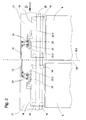
- Fig. 2 shows (enlarged and schematically) marked in Fig. 1 view A of the upper portion of one of the shaft doors 7 in Fig. 1.
- This shaft door has two shaft door leaves 8, which are fastened to a respective door leaf carrier 18.
- These door leaf supports 18 are guided horizontally displaceable by means of guide rollers 19 on a guide rail 20, wherein the guide rail 20 is fastened to a door support 21 connected to the door frame.
- 10.3 designates the jet of the shaft door monitoring sensor 10 described in connection with FIG.
- On the right side of Fig. 2 it is shown how the shaft door latch 22 locks the door leaf support 18 with a locking stop 23 immovably connected to the door support 21 when the landing door leaf 8 is completely closed.
- the shaft door latch 22 is held in an unlocking position, not shown here, by the door operating mechanism acting from the elevator car. Once the car and the shaft doors are closed, this effect is released, and the shaft door latch 22 tilts due to its closing weight 22.1 in its locking position.
- the locking hook 22.2 of the shaft door latch acts on two mounted on the immovable locking stop and one of the blades 12 bearing handlebar lever 24, that these pivot from their - shown on the left - basic position to the right, causing a shift of the aperture 12 to the right - and thus the beam path of the beam 10.3 out - causes.
- a landing door wing. 8 shown, which is not completely closed (door gap 25), and its shaft door latch 22 is why - possibly for another reason - not in its locked position located. Because in this situation the locking hook 22.2 of the shaft door bolt 22 is not on the aperture 12th supporting handlebar lever 24 acts, the aperture remains in their itself without outside influence by itself from the handlebar lever assembly resulting basic position in which they the beam path of Beam 10.3 interrupts.
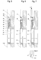
- FIG. 2 A side view D of the described shaft door arrangement according to FIG. 2, which also shows the position of the beam 10.3, is shown in FIG.
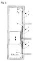
- FIG. 3 again shows an elevator installation 1 with a shaft door monitoring sensor 10, the position of the landing door wing 8 and its shaft door latch with the help of at least one of bundled electromagnetic waves formed beam 10.3 -
- a laser light beam - monitored Preferably a laser light beam - monitored.
- transmitter 10.1 and receiver 10.2 are transmitter 10.1 and receiver 10.2 in the same shaft end region, preferably in the same Housing arranged, and emitted by the transmitter 10.1 beam 10.3 is on one in the area of the opposite shaft end mounted reflection surface 11 directed, which the beam 10.3 reflected to the transmitter 10.1, unless the beam due to a not completely closed shaft door leaf 8 and / or one is not in the locked position Shaft door bolt is interrupted.
- At least one laser light beam extends 10.3 so along the shaft doors 7 containing Shaft wall that he is not fully closed Shaft door leaf 8 and / or through one of the panels 17th is interrupted, which protrude into the beam 10.3, if they do not belong to the respective, in locking position Hinge door latch are prevented from it. Details on the arrangement of these - shown here only schematically - Apertures 17 are explained in the following Fig. 4.
- Fig. 4 shows (enlarged) in Fig. 3 with B marked view of the upper portion of one of the shaft doors shown in Fig. 3 7.
- This shaft door also has two shaft door leaves 8, which are fastened to a respective door leaf carrier 18.
- These door leaf supports 18 are guided horizontally displaceable by means of guide rollers 19 on a guide rail 20, wherein the guide rail 20 is fastened to a door support 21 connected to the door frame.
- a beam 10.3 - preferably a laser light beam - can be seen on the left and right of the two shaft door leaves 8, as already mentioned in connection with FIGS. 1 and 3.
- the two beams are emitted and detected by a shaft door monitoring sensor 10 which are installed in the elevator shaft for monitoring each of the left-side or right-side row of landing door panels.
- a shaft door latch 22 is articulated to each of the two door leaf carrier 18.
- the shaft door latch 22 locks the door leaf support 18 with a locking stop 23 immovably connected to the door support 21 when the landing door leaf 8 is completely closed.
- the shaft door latch 22 is held in an unlocking position, not shown here, by the door operating mechanism acting from the elevator car.
- the shaft door latch tilts due to its closing weight 22.1 in its - shown here - on the right - locking position.
- the locking hook 22.2 of the shaft door bolt acts on two mounted on the immovable locking stop 23 and one of the panels 17 bearing handlebar lever 24 that they pivot from their - recognizable on the left side - basic position to the left, causing a shift of the panel 17 to the left - And thus out of the beam path of the beam 10.3 - causes.
- FIG. 4 again shows a shaft door leaf 8, which is not completely closed (door gap 25), and its shaft door latch 22 is why - possibly from a other reason - not in his locked position located. Since in this situation the locking hook 22.2 the shaft door bolt 22 is not on the diaphragm 17 bearing Handlebar lever 24 acts, the aperture 17 remains in her without external influence by itself from the handlebar lever assembly resulting basic position in which they the beam path of Beam 10.3 interrupts. With a suitably attached spring the self-taking of the iris basic position, in which the beam 10.3 is interrupted, still secured become.
- a side view E of the above Shaft door arrangement according to FIG. 4, from which the position of the Rays 10.3 shows, is shown in Fig. 6.
- the method described above in connection with FIG. 4 has the advantage that no beam as in the arrangement according to FIGS. 1 and 2 within the relatively narrow gap between the landing door thresholds and the car door sill but that space must be side by side the shaft doors is used.
- the emission of the beam must not be interrupted during the door opening phase.
- this method brings increased security the shaft door monitoring, because on the one hand a not completely closed shaft door leaf directly interrupts the beam and on the other hand, because of the separate monitoring of the left-side and right-side shaft door leaves a Certain safety redundancy results, even if their movements not synchronized in each case mechanically.
- Fig. 6 shows a side view of the shaft door assembly according to Fig. 4 (view E) in the closed position of each Shaft door leaf 8 together with the locking state his Schachtfriegels 22 monitored by a beam 10.3 becomes.
- the vertical beam 10.3 runs so close behind the Schliesskante opposite narrow side of the closed Bay door leaf 8 that he is not complete closed shaft door leaf 8 through the lower edge 8.1 or its upper edge 8.2 and / or by the not of the shaft door latch 22 retracted aperture 17 is interrupted.
- the 6 correspond to components of the shaft door, with the exception of the differently arranged aperture 17, the related with FIGS. 4 and 5 explained components.
- Fig. 7 shows the side view of a variant of the shaft door monitoring with improved functionality. Such will be achieved in that the closed position of the elevator shaft stacked shaft door leaf 8 and the Locking state of the shaft door leaves 8 assigned Shaft door latch 22 are monitored separately. Will be realized For example, such monitoring can be done by everyone of the two shown in Fig. 4 single rays 10.3 by two parallel, staggered in the direction of the plane of the drawing Rays 10.3 (Fig. 7) is replaced, one of which the lower edge 8.1 or the upper edge 8.2 of the associated Shaft door leaf 8 and the other the slightly laterally of the Shaft door leaf 8 arranged aperture 17 (corresponding to the Aperture 17 in Fig. 4) monitored. The two parallel rays 10.3 are doing so by two separate shaft door monitoring sensors generated, the transmitter / receiver principle or the Reflection principle can be used.
- the shaft door monitoring sensor for example due to the duration of individual light pulses or the phase position of the laser light detected at the receiver, emitted from the beam determine the distance traveled. From the measured distance the elevator control can determine the floor on which an error condition exists and this information is available to the user Store maintenance personnel, transmit to a maintenance center, and / or to use, in the area of the affected shaft door to activate an optical or acoustic warning signal. In the case of a self-contained, but not correct It is also possible to program a locked landing door leaf to start, at which, after all passengers the elevator car have left the elevator car in creeper to faulty floor is driven, where by opening and Close of cabin and shaft door is tried, the Fix locking error.
- FIG. 8 and 9 schematically show a group of shaft doors 7 arranged one above the other, whose closed state and locking state are monitored by means of a multiply deflected jet 10.3.
- FIG. 9 shows a view F from the right of the mentioned group of shaft doors.
- the beam 10.3 is emitted vertically upward from a transmitter 10.1 of a shaft door monitoring sensor 10 mounted below a lowermost shaft door of the group, next to the left-side shaft door wings 8.3. After passing through a first vertical section 10.3.1 of its beam path, it is deflected above the uppermost shaft door of the monitored group by a first beam deflection device 32.1 to the right to a second beam deflection device 32.2.
- the beam is again deflected by 90 °, so that this laterally next to the right side shaft door leaves 8.4 a second vertical section 10.3.2 passes in the downward direction and pushes on a third beam deflecting 32.3.
- the jet in a third vertical section 10.3.3 again runs upwards to the beam deflection device 32.2, which deflects it by 90 ° to the left (in FIG. 8) to the beam deflection device 32.1.
- the beam is deflected one last time by 90 °, after which it travels a fourth vertical section 10.3.4 and finally is detected by a receiver 10.2 of the shaft door monitoring sensor 10.
- the beam can be influenced by not fully closed shaft door leaves or by panels 17, which are not retracted by their associated shaft door latch.
- the left-side shaft door leaves 8.3 can affect the vertical section 10.3.1 and the right-side shaft door leaves 8.4 the vertical section 10.3.2 of the beam 10.3.
- the left-side diaphragms 17.1 can influence the vertical section 10.3.4 and the right-side diaphragms 17.2 the vertical section 10.3.3 of the beam 10.3.
- beam deflection 32.1, 32.2, 32.3, 32.4 can Mirror and / or suitable optical prisms can be used.
- a shaft door monitoring sensor 10 Used to monitor the shaft doors is a shaft door monitoring sensor 10 used with distance measurement, so can with the described method with the first the landing door wings be detected in a fault incident, whether a the shaft door 8.3, 8.4 not completely closed is, or if only one of the position of the aperture 17.1, 17.2 determining shaft door latch is not in its locked position located. Thanks to this distinction can also in this single-jet shaft door monitoring device in case of failure the already mentioned situation-adapted reactions are triggered.
- the manner in which the impact of the shaft door position and / or shaft door lock position on the beams is realized can be varied almost indefinitely.
- the shaft door lock position can be transmitted directly or via joints and linkages to the position of shutters or reflecting surfaces in the form of flaps, sliders, etc., so that they can influence the beams extending in suitable zones in the vicinity of the shaft doors.
Landscapes
- Engineering & Computer Science (AREA)
- Automation & Control Theory (AREA)
- Elevator Door Apparatuses (AREA)
Abstract
Description
Bei Aufzugsanlagen herkömmlicher Art ist auch das Lastaufnahmemittel (Aufzugskabine) mit einer Türe ausgerüstet, die als Kabinentüre bezeichnet wird und sich zusammen mit der Aufzugskabine von Stockwerk zu Stockwerk bewegt. Das Öffnen und Schliessen der Türen wird normalerweise während eines Stockwerkshalts der Aufzugskabine durch einen von einer Aufzugssteuerung gesteuerten Kabinentürantrieb bewirkt. Dabei werden die Kabinentürflügel mit den jeweils korrespondierenden Schachttürflügeln gekoppelt, so dass die Schachttürflügel die Bewegung der Kabinentürflügel mitmachen.
Für die Sicherheit der Benutzer der Aufzugsanlage und der Passanten im Gebäude ist es von grosser Wichtigkeit, dass eine Schachttüre nur dann offen sein darf, wenn die Aufzugskabine auf dem zugeordneten Stockwerk anhält. Um dies zu gewährleisten, werden, neben anderen Aufzugs-Parametern, die Lagen sowohl der Schachttürflügel wie auch der die Schachttürflügel verriegelnden Schachttürriegel überwacht. Üblicherweise geschieht dies dadurch, dass jedem Schachttürriegel ein Sicherheitskontakt zugeordnet ist, der einen Teil eines elektrischen Sicherheitskreises bildet und diesen bei nicht korrekter Verriegelung der Schachttürflügel unterbricht.
Solche Sicherheitskreise, die im Falle von hohen Gebäuden eine Reihenschaltung von mehr als zwanzig Sicherheitskontakten aufweisen können, sind als eine der Haupt-Ursachen für Störungen des Aufzugsbetriebs bekannt. Infolge von Korrosion und Verschmutzung erhöht sich in relativ kurzer Zeit der Kontaktwiderstand der einzelnen Sicherheitskontakte, was bei Reihenschaltung vieler Kontakte einen derart hohen Spannungsabfall bewirkt, dass das Sicherheitskreis-System den Aufzug auch bei korrekt geschlossenen Türen abschaltet. Ausserdem ist die Suche nach einem einzelnen defekten Sicherheitskontakt oder nach einer nicht korrekt geschlossenen Schachttüre in einem Gebäude mit vielen Stockwerken äusserst zeitraubend.
Zusätzliche Probleme mit der Überwachung der Schachttüren haben sich in den letzten Jahren durch Personen ergeben, die in unerlaubter Weise in den Aufzugsschacht eindringen, sei es um das risikoreiche "Aufzug-Surfen" zu betreiben oder um die Aufzugskabine zwischen zwei Stockwerken zu blockieren und die Aufzugspassagiere zu bedrohen oder zu berauben.
- Messung der Laufzeit einzelner Impulse der den Strahl bildenden elektromagnetischen Welle. Dieses als "Time of Flight Measurement (TOF)" bekannte Verfahren beruht darauf, dass von einem Sender einzelne elektromagnetische Impulse emittiert werden, die - in der vorliegenden Anwendung nach Reflexion an einer reflektierenden Fläche - von einem Empfänger detektiert werden. Die "Flugzeit" der einzelnen Impulse wird mittels einer elektronischen Schaltung erfasst, woraus sich, unter Berücksichtigung der bekannten Ausbreitungsgeschwindigkeit von elektromagnetischen Wellen, die vom Impuls zurückgelegte Distanz errechnen lässt. Die Anwendung dieses Prinzips erfolgt vorzugsweise mit Laserlichtstrahlen oder - für geringere Distanzen - mit gebündeltem, inkohärentem Infrarotlicht. TOF-Lasergeräte eignen sich für den Einsatz in höchsten Gebäuden, liefern Messwerte mit hoher Auflösung, sind vielfach erprobt und handelsüblich erhältlich.
- Messung der Phasenverschiebung (Phase Shift Measurement) zwischen Emission und Empfang einer den Strahl bildenden, kontinuierlich emittierten elektromagnetischen Welle. Vorzugsweise werden bei diesem Messprinzip kohärentes Licht abstrahlende Laser als Strahlerzeuger verwendet. Die Erfassung der vom Strahl zwischen Sender und Empfänger - hier via Reflexionsfläche - zurückgelegten Distanz beruht auf der Messung der Verschiebung der Phasenlage der abgestrahlten sinusförmigen Welle auf ihrem Weg vom Sender (Emitter) zum Empfänger (Detektor). Die Wellenlänge muss dabei mindestens der zu messenden Distanz entsprechen. Bei relativ grossen Distanzen wird dabei die Messauflösung gegebenenfalls zu gering. In diesem Fall werden mehrere Wellen unterschiedlicher Wellenlänge abgestrahlt, wobei diejenige mit der grossen Wellenlänge einen relativ ungenauen Absolutwert ergibt und diejenige(n) mit der(den) kleineren Wellenlänge(n) eine höhere Auflösung ermöglicht (ermöglichen).
Beispielsweise können damit der Schachttürflügel und der zugehörige Schachttürriegel unabhängig voneinander überwacht werden, oder es können mehrere untereinander mechanisch gekoppelte Schachttürflügel und/oder die Schachttürriegel mehrflügeliger Schachttüren unabhängig voneinander überwacht werden. Damit ergibt sich einerseits eine sicherheitstechnisch wünschbare Redundanz der Schachttüren-Überwachung. Andererseits kann zwischen nicht geschlossenen Schachttürflügeln und nicht verriegelten Schachttürriegeln unterschieden werden, was ermöglicht, optimal auf unterschiedliche Störungsmeldungen zu reagieren. Beispielsweise kann bei Detektion eines nicht verriegelten Schachttürriegels bei noch geschlossener Schachttüre, anstelle einer sofortigen Notbremsung, eine Fahrt der Aufzugskabine bis zum nächsten Halt fortgesetzt werden, wodurch eine Einschliessung von Passagieren vermieden werden kann.
- Mit einem einzigen Strahl, d. h. mit einem einzigen Schachttürüberwachungssensor, können jeweils zwei oder mehrere seitlich versetzt angeordnete Schachttürflügel von mehreren übereinander angeordneten Schachttüren überwacht werden.
- Mit einem einzigen Strahl können die Schachttürflügel mehrerer übereinander angeordneter Schachttüren und zu diesen im Schachtquerschnitt versetzt angeordnete, abhängig vom Verriegelungszustand zugehöriger Schachttürriegel positionierte Blenden überwacht werden.
- Mit einem einzigen Strahl eines Schachttürüberwachungssensors mit Distanzmessung können mit mindestens einem vertikalen Abschnitt des Strahlenwegs zuerst alle Schachttürflügel und, mit mindestens einem durch Umlenkung erzeugten, seitlich versetzten, weiteren Abschnitt des Strahlenwegs, alle abhängig vom Verriegelungszustand zugehöriger Schachttürriegel positionierten Blenden überwacht werden. Wird der Strahl durch einen nicht vollständig geschlossenen Schachttürflügel und/oder durch eine der Blenden reflektiert, so kann aufgrund der detektierten Distanz zum Störobjekt erkannt werden, ob wenigstens alle Schachttürflügel geschlossen sind, was bereits beschriebene, differenzierte Steuerungsreaktionen auf die signalisierte Störung ermöglicht.
- Fig. 1
- einen Vertikalschnitt durch einen Aufzugschacht mit einer Aufzugskabine und mehreren Schachttüren, wobei die Schachttüren mittels eines von einem Sender zu einem Empfänger emittierten Strahls überwacht werden,
- Fig. 2
- eine vom Schachtinneren her gesehene zweiflügelige Schachttüre mit zwei Verriegelungseinrichtungen und einem Überwachungsstrahl,
- Fig. 3
- einen Vertikalschnitt durch einen Aufzugschacht mit einer Aufzugskabine und mehreren Schachttüren, wobei die Schachttüren mittels eines Strahls überwacht werden, der von einem Sender zu einer Reflexionsfläche emittiert und von dieser zu einem Empfänger reflektiert wird,
- Fig. 4
- eine vom Schachtinneren her gesehene zweiflügelige Schachttüre mit zwei Verriegelungseinrichtungen und zwei Überwachungsstrahlen.
- Fig. 5, 6, 7
- Seitenansichten der in Fig. 2 und Fig. 4 dargestellten Schachttüren mit der Lage der Überwachungsstrahlen
- Fig. 8
- eine Ansicht vom Schachtinneren auf eine Gruppe von Schachttüren, deren Geschlossenzustand und deren Verriegelung mittels eines umgelenkten Strahls überwacht werden
- Fig. 9
- eine Seitenansicht auf die Gruppe von Schachttüren gemäss Fig. 8
Im geschlossenen Zustand sind die Schachttürflügel 8 mittels eines - hier nicht gezeigten - Schachttürriegels mit einem feststehenden Teil der Schachttüren verriegelt.
Mit 10.1 ist ein im Bereich der Schachtgrube nahe bei der die Schachttüren enthaltenden Schachtwand installierter Sender bezeichnet. Dieser emittiert - mindestens während einer Detektionsphase - einen Strahl 10.3 in Form von gebündelten elektromagnetischen Wellen, vorzugsweise einen Laserlichtstrahl. Der vom Sender 10.1 emittierte Strahl 10.3 ist auf einen im Bereich des Schachtkopfs fixierten Empfänger 10.2 gerichtet, der den Strahl 10.3 empfängt, sofern dieser nicht infolge eines nicht vollständig geschlossenen Schachttürflügels 8 und/oder eines sich nicht in Verriegelungsstellung befindenden Schachttürriegels unterbrochen wird. Sender 10.1 und Empfänger 10.2 bilden zusammen einen Schachttürüberwachungssensor 10. Die hier beschriebene Anordnung ist im Folgenden als Sender/Empfänger-Prinzip bezeichnet. Wird der Strahl 10.3 während der Detektionsphase unterbrochen, so signalisiert der Schachttürüberwachungssensor der Aufzugssteuerung, dass einer der Schachttürflügel 8 nicht vollständig geschlossen ist oder einer der Schachttürriegel sich nicht in Verriegelungsstellung befindet. Als Detektionsphasen sind diejenigen Zeitabschnitte bezeichnet, in denen bei programmgemässem Betriebsablauf alle Schachttüren geschlossen und verriegelt sein müssen.
Mit 10.3 ist der im Zusammenhang mit Fig. 1 beschriebene Strahl des Schachttürüberwachungssensors 10 bezeichnet. An jedem der beiden Türflügelträger 18 ist jeweils ein Schachttürriegel 22 gelenkig montiert.
Auf der rechten Seite von Fig. 2 ist dargestellt, wie der Schachttürriegel 22 den Türflügelträger 18 mit einem unbeweglich mit dem Türsupport 21 verbundenen Verriegelungsanschlag 23 verriegelt, wenn der Schachttürflügel 8 vollständig geschlossen ist. Während des Öffnens und Schliessens des Schachttürflügels 8 wird der Schachttürriegel 22 durch den von der Aufzugskabine aus wirkenden Türbetätigungsmechanismus auf eine hier nicht dargestellte Weise in Entriegelungsstellung gehalten. Sobald die Kabinen- und die Schachttüre geschlossen sind, wird diese Wirkung aufgehoben, und der Schachttürriegel 22 kippt infolge seines Schliessgewichts 22.1 in seine Verriegelungsstellung. Dabei wirkt der Verriegelungshaken 22.2 des Schachttürriegels so auf zwei auf dem unbeweglichen Verriegelungsanschlag montierte und eine der Blenden 12 tragende Lenkerhebel 24 ein, dass diese aus ihrer - links dargestellten - Grundstellung nach rechts schwenken, was eine Verschiebung der Blende 12 nach rechts - und damit aus dem Strahlweg des Strahls 10.3 heraus - bewirkt.
Eine Seitenansicht D der beschriebenen Schachttüranordnung gemäss Fig. 2, aus der auch die Lage des Strahls 10.3 hervorgeht, ist in Fig. 5 dargestellt.
Links und rechts der beiden Schachttürflügel 8 ist je ein Strahl 10.3 - vorzugsweise ein Laserlichtstrahl - erkennbar, wie im Zusammenhang mit Fig. 1 und Fig. 3 bereits erwähnt. Die beiden Strahlen werden von je einem Schachttürüberwachungssensor 10 emittiert und detektiert, die zur Überwachung von jeweils der linksseitigen oder der rechtsseitigen Reihe von Schachttürflügeln im Aufzugsschacht installiert sind. Es sind das Einwegstrahlprinzip, bei dem Sender und Empfänger voneinander entfernt angeordnet sind, wie auch das Reflexionsprinzip, wie im Zusammenhang mit Fig. 3 beschrieben, anwendbar.
Auch hier ist an jedem der beiden Türflügelträger 18 jeweils ein Schachttürriegel 22 gelenkig montiert.
Auf der rechten Seite von Fig. 4 ist erkennbar, wie der Schachttürriegel 22 den Türflügelträger 18 mit einem unbeweglich mit dem Türsupport 21 verbundenen Verriegelungsanschlag 23 verriegelt, wenn der Schachttürflügel 8 vollständig geschlossen ist. Während des Öffnens und Schliessens des Schachttürflügels 8 wird der Schachttürriegel 22 durch den von der Aufzugskabine aus wirkenden Türbetätigungsmechanismus auf eine hier nicht dargestellte Weise in Entriegelungsstellung gehalten. Sobald die Kabinen- und die Schachttüre geschlossen sind, wird diese Wirkung aufgehoben, und der Schachttürriegel kippt infolge seines Schliessgewichts 22.1 in seine - hier auf der rechten Seite gezeigten - Verriegelungsstellung. Dabei wirkt der Verriegelungshaken 22.2 des Schachttürriegels so auf zwei auf dem unbeweglichen Verriegelungsanschlag 23 montierte und eine der Blenden 17 tragende Lenkerhebel 24 ein, dass diese aus ihrer - auf der linken Seite erkennbaren - Grundstellung nach links schwenken, was eine Verschiebung der Blende 17 nach links - und damit aus dem Strahlweg des Strahls 10.3 heraus - bewirkt.
Zu erkennen sind in Fig. 5 die folgenden Komponenten:
- die die Schachttüren 7 enthaltende Schachtwand 30 mit der Türöffnung 31,
- der an der Schachtwand fixierte Türsupport 21 mit der an ihm befestigten Führungsschiene 20
- der den Schachttürflügel 8 tragende Türflügelträger 18, der mittels der an ihm angebrachten Führungsrollen 19 an der Führungsschiene 20 geführt ist
- der am Türflügelträger 18 gelenkig gelagerte Schachttürriegel 22, der den Türflügelträger 18 mit dem Verriegelungsanschlag 23 verriegelt
- die durch den Schachttürriegel 22 bewegten Lenkerhebel 24, die, in Abhängigkeit von der Stellung des Schachttürriegels 22, die Blende 12 in den Strahlweg des zentralen Strahls 10.3 hinein oder aus diesem heraus bewegen.
Wie in Fig. 8 erkennbar, wird der Strahl 10.3 von einem unterhalb einer untersten Schachttüre der Gruppe angebrachten Sender 10.1 eines Schachttürüberwachungssensors 10 seitlich neben den linksseitigen Schachttürflügeln 8.3 vertikal nach oben emittiert. Nach dem Durchlaufen eines ersten Vertikalbschnitts 10.3.1 seines Strahlwegs wird er oberhalb der obersten Schachttüre der überwachten Gruppe durch eine erste Strahlumlenkeinrichtung 32.1 nach rechts zu einer zweiten Strahlumlenkeinrichtung 32.2 umgelenkt. Durch diese wird der Strahl erneut um 90° umgelenkt, so dass dieser seitlich neben den rechtsseitigen Schachttürflügeln 8.4 einen zweiten Vertikalabschnitt 10.3.2 in Abwärtsrichtung durchläuft und auf eine dritte Strahlumlenkeinrichtung 32.3 stösst. Diese lenkt den Strahl 10.3 um 180° um, wobei gleichzeitig eine Versetzung des Strahls um eine gewisse Distanz X in Richtung auf die Schachtwand zu erfolgt, wie in Fig. 9 erkennbar ist. Anschliessend läuft der Strahl in einem dritten Vertikalabschnitt 10.3.3 wieder nach oben zur Strahlumlenkeinrichtung 32.2, die ihn um 90° nach links (in Fig. 8) zur Strahlumlenkeinrichtung 32.1 ablenkt. Hier wird der Strahl ein letztes Mal um 90° abgelenkt, wonach er einen vierten Vertikalabschnitt 10.3.4 zurücklegt und schliesslich von einem Empfänger 10.2 des Schachttürüberwachungssensors 10 detektiert wird. Im Bereich seiner Vertikalabschnitte kann der Strahl durch nicht vollständig geschlossene Schachttürflügel oder durch Blenden 17, welche nicht durch ihren zugehörigen Schachttürriegel zurückgezogen sind, beeinflusst werden. Die linksseitigen Schachttürflügel 8.3 können den Vertikalabschnitt 10.3.1 und die rechtsseitigen Schachttürflügel 8.4 den Vertikalabschnitt 10.3.2 des Strahls 10.3 beeinflussen. Die linksseitigen Blenden 17.1 können den Vertikalabschnitt 10.3.4 und die rechtsseitigen Blenden 17.2 den Vertikalabschnitt 10.3.3 des Strahls 10.3 beeinflussen.
Beispielsweise kann die Schachttürriegelstellung direkt oder über Gelenke und Gestänge auf die Position von Blenden oder Reflexionsflächen in Form von Klappen, Schiebern, etc. übertragen werden, damit diese die sich in geeigneten Zonen in Nähe der Schachttüren erstreckenden Strahlen beeinflussen können.
Claims (13)
- Verfahren zur Überwachung von Schachttüren (7) einer Aufzugsanlage (1) mit einem Aufzugsschacht (2) und einer entlang einer Schachtwand (30) vertikal bewegbaren Aufzugskabine (3), wobei die Schachtwand (30) mehrere Schachttüren (7) mit je mindestens einem horizontal verschiebbaren Schachttürflügel (8) aufweist, wobei beim Halten der Aufzugskabine (3) auf einem Stockwerk mindestens ein Schachttürflügel (8) der jeweils der Aufzugskabine gegenüberliegenden Schachttüre (7) durch einen korrespondierenden Kabinentürflügel (5) geöffnet und geschlossen wird, wobei die Aufzugsanlage (1) eine Aufzugssteuerung umfasst, durch die die Bewegungen der Aufzugskabine (3), des Kabinentürflügels (5) und damit des jeweils korrespondierenden Schachttürflügels (8) gesteuert werden, und wobei eine Geschlossenstellung der Schachttürflügel (8) durch mindestens einen berührungslos wirkenden, elektromagnetische Wellen emittierenden Schachttürüberwachungssensor überwacht wird,
dadurch gekennzeichnet, dass mindestens während gewissen Detektionsphasen von einem im Aufzugsschacht angebrachten Sender (10.1) des Schachttürüberwachungssensors (10) ein sich über mehrere Stockwerke erstreckender Strahl (10.3) in Form von elektromagnetischen Wellen emittiert wird, der von einem Empfänger (10.2) des Schachttürüberwachungssensors (10) detektiert wird, wobei der Strahl (10.3) so angeordnet ist, dass er, wenn einer der Schachttürflügel (8) nicht vollständig geschlossenen ist und/oder ein Schachttürriegel (22) sich nicht in Verriegelungsstellung befindet, derart beeinflusst wird, dass vom Empfänger (10.2) des Schachttürüberwachungssensors (10) erkannt wird, dass eine der Schachttüren (7) nicht vollständig geschlossen und/oder nicht verriegelt ist, wobei diese Information vom Schachttürüberwachungssensor (10) an die Aufzugssteuerung signalisiert wird. - Verfahren nach Anspruch 1, dadurch gekennzeichnet, dass durch die Aufzugssteuerung eine sich in Fahrt befindliche Aufzugskabine (3) gestoppt wird, und/oder dass optische und/oder akustische Warnsignale auf mindestens einem der Stockwerke aktiviert werden können, wenn der Schachttürüberwachungssensor (10) während eines Betriebszustands, in welchem alle Schachttüren (7) vollständig geschlossen und verriegelt sein sollten, einen nicht vollständig geschlossenen Schachttürflügel (8) und/oder einen sich nicht in Verriegelungsstellung befindenden Schachttürriegel (22) signalisiert.
- Verfahren nach Anspruch 1 oder 2, dadurch gekennzeichnet, dass als Strahl (10.3) ein gebündelter Strahl aus inkohärenten Lichtwellen oder ein Laserlichtstrahl aus kohärenten Lichtwellen verwendet wird.
- Verfahren nach Anspruch 3, dadurch gekennzeichnet, dass für den emittierten Lichtstrahl Licht aus den Wellenlängenbereichen von Ultraviolett-Licht, von sichtbarem Licht oder von Infrarot-Licht verwendet wird.
- Verfahren nach einem der Ansprüche 1 bis 4, dadurch gekennzeichnet, dass mindestens während der Detektionsphasen der Strahl (10.3) von einem Sender (10.1) in Richtung auf einen mehrere Stockwerkdistanzen von diesem entfernt angebrachten Empfänger (10.2) emittiert wird, und dass vom Empfänger (10.2) detektiert wird, ob der Strahl (10.3) den Empfänger (10.2) erreicht oder infolge eines nicht vollständig geschlossenen Schachttürflügels (8) oder eines sich nicht in Verriegelungsstellung befindenden Schachttürriegels (22) unterbrochen ist.
- Verfahren nach einem der Ansprüche 1 bis 4, dadurch gekennzeichnet, dass mindestens während der Detektionsphasen der Strahl (10.3) von einem Sender (10.1) in Richtung auf eine mehrere Stockwerkdistanzen von diesem entfernt angebrachte Reflexionsfläche (11) emittiert wird, die so ausgerichtet ist, dass ein ankommender Strahl (10.3) zu einem im Bereich des Senders (10.1) installierten Empfänger (10.2) reflektiert wird, wobei vom Empfänger (10.2) detektiert wird, ob der emittierte Strahl (10.3) den Empfänger (10.2) erreicht oder infolge eines nicht vollständig geschlossenen Schachttürflügels (8) oder eines sich nicht in Verriegelungsstellung befindenden Schachttürriegels (22) unterbrochen ist.
- Verfahren nach einem der Ansprüche 1 bis 4, dadurch gekennzeichnet, dass mindestens während der Detektionsphase der Strahl (10.3) von einem Sender (10.1) in Richtung auf eine mehrere Stockwerksdistanzen von diesem entfernt angebrachten Haupt-Reflexionsfläche (13) emittiert wird,
dass der Strahl von dieser Haupt-Reflexionsfläche (13) oder von einer Reflexionsfläche (8.1, 8.2, 17), die im Falle eines nicht vollständig geschlossenen Schachttürflügels (8) und/oder eines sich nicht in Verriegelungsstellung befindenden Schachttürriegels (22) in den Strahl hineinragt, zu einem im Bereich des Senders (10.1) vorhandenen Empfänger (10.2) reflektiert wird, und
dass der Schachttürüberwachungssensor (10) mit Sender (10.1) und Empfänger (10.2), so ausgebildet ist, dass die vom Strahl (10.3) auf seinem Weg vom Sender (10.1) über eine der Reflexionsflächen (13, 8.1, 8.2, 17) zurück zum Empfänger (10.2) zurückgelegte Distanz ermittelt und an die Aufzugssteuerung signalisiert werden kann. - Verfahren nach Anspruch 7 dadurch gekennzeichnet, dass, sobald und solange die ermittelte, vom Strahl (10.3) zurückgelegte Distanz kürzer als der Weg vom Sender (10.1) zur Haupt-Reflexionsfläche (13) und zurück zum Empfänger (10.2) ist, durch den Schachttürüberwachungssensor (10) oder durch eine nachgeschaltete Auswerteeinrichtung ein nicht vollständig geschlossener Schachttürflügel (8) und/oder ein sich nicht in Verriegelungsstellung befindender Schachttürriegel (22) an die Aufzugssteuerung signalisiert wird, wobei, wenn eine solche Situation während eines Betriebszustands auftritt, in dem alle Schachttüren (7) geschlossen und verriegelt sein sollten, die Distanz zur momentan wirkenden Reflexionsfläche und/oder eine daraus ermittelte Identifikation des Stockwerks, von welchem aus der Strahl (10.3) reflektiert wird, gespeichert und/oder angezeigt werden.
- Verfahren nach Anspruch 7 oder 8, dadurch gekennzeichnet, dass die vom reflektierten Strahl (10.3) zurückgelegte Distanz unter Anwendung einer der folgenden Methoden ermittelt wird:Messung der Laufzeit einzelner Impulse der den Strahl (10.3) bildenden elektromagnetischen Welle (Time of Flight Measurement)Messung der zwischen Emission und Empfang stattfindenden Verschiebung der Phasenlage der den Strahl (10.3) bildenden, kohärent emittierten elektromagnetischen Wellen (Phase Shift Measurement).
- Verfahren nach einem der vorhergehenden Ansprüche, dadurch gekennzeichnet, dass zur Überwachung der Schachttüren (7) mehrere unabhängige Strahlen (10.3) angewendet werden,wobei Schachttürflügel (8) und Schachttürriegel (22) unabhängig voneinander überwacht werden, oderwobei die Schachttürflügel (8) und/oder die Schachttürriegel (22) mehrflügeliger Schachttüren unabhängig voneinander überwacht werden.
- Verfahren nach einem der vorhergehenden Ansprüche,
dadurch gekennzeichnet, dass ein von einem Sender 10.1 emittierter Strahl 10.3 auf seinem Weg zu einem Empfänger 10.2 mit Hilfe von wenigstens einer im Aufzugsschacht (2) fixierten Strahlumlenkeinrichtung (33) so im Aufzugsschacht umgelenkt wird, dass vom Strahl (10.3) eine mehreren Stockwerkshöhen entsprechende vertikale Distanz mehrmals an unterschiedlichen Positionen des horizontalen Schachtquerschnitts durchlaufen wird, wobei der Strahl durch nicht vollständig geschlossene Schachttürflügel (8) und/oder durch vom Verriegelungszustand der Schachttürriegel 22 abhängig positionierte Blenden (12; 17) beeinflusst werden kann, deren vom Strahl erfasste Bereiche an den genannten unterschiedlichen Positionen angeordnet sind. - Verfahren nach einem der vorhergehenden Ansprüche,
dadurch gekennzeichnet, dass, wenn während eines Betriebszustands, in dem alle Schachttüren (7) geschlossen sein sollten, ein nicht vollständig geschlossener Schachttürflügel (8) signalisiert wird, fernsteuerbare, auf die Schachttürflügel (8) wirkende Zusatzverriegelungen aktiviert werden können. - Verfahren nach einem der vorhergehenden Ansprüche,
dadurch gekennzeichnet, dass in Aufzugsanlagen, die mit einem Schachttürüberwachungssensor (10) mit Distanzerkennung ausgerüstet sind, optische und/oder akustische Warnsignale und/oder fernsteuerbare, auf die Schachttürflügel wirkende Zusatzverriegelungen auf ausschliesslich demjenigen Stockwerk aktiviert werden können, bei dessen Schachttüre (7) während eines Betriebszustands, in dem alle Schachttüren geschlossen und verriegelt sein sollten, ein nicht vollständig geschlossener Schachttürflügel (8) und/oder ein sich nicht in Verriegelungsstellung befindender Schachttürriegel (22) detektiert wird (werden).
Priority Applications (1)
| Application Number | Priority Date | Filing Date | Title |
|---|---|---|---|
| EP20030009423 EP1359112B1 (de) | 2002-05-03 | 2003-04-25 | Verfahren zur Überwachung von Schachttüren einer Aufzugsanlage |
Applications Claiming Priority (3)
| Application Number | Priority Date | Filing Date | Title |
|---|---|---|---|
| EP02405360 | 2002-05-03 | ||
| EP02405360 | 2002-05-03 | ||
| EP20030009423 EP1359112B1 (de) | 2002-05-03 | 2003-04-25 | Verfahren zur Überwachung von Schachttüren einer Aufzugsanlage |
Publications (2)
| Publication Number | Publication Date |
|---|---|
| EP1359112A1 true EP1359112A1 (de) | 2003-11-05 |
| EP1359112B1 EP1359112B1 (de) | 2008-03-26 |
Family
ID=29217242
Family Applications (1)
| Application Number | Title | Priority Date | Filing Date |
|---|---|---|---|
| EP20030009423 Expired - Lifetime EP1359112B1 (de) | 2002-05-03 | 2003-04-25 | Verfahren zur Überwachung von Schachttüren einer Aufzugsanlage |
Country Status (1)
| Country | Link |
|---|---|
| EP (1) | EP1359112B1 (de) |
Cited By (2)
| Publication number | Priority date | Publication date | Assignee | Title |
|---|---|---|---|---|
| WO2015139747A1 (en) * | 2014-03-19 | 2015-09-24 | Otis Elevator Company | Method and device for monitoring the movement of at least one door, in particular an elevator door |
| DE102019212726A1 (de) * | 2019-08-26 | 2021-03-04 | Thyssenkrupp Elevator Innovation And Operations Ag | Aufzugsanlage die einen Fahrkorb abhängig von einem Schließzustandssignal und einer Position des Fahrkorbs in einen Sicherheitsbetriebszustand überführt |
Citations (3)
| Publication number | Priority date | Publication date | Assignee | Title |
|---|---|---|---|---|
| US5616895A (en) * | 1993-10-06 | 1997-04-01 | Inventio Ag | Door safety circuit for monitoring of story doors in lift installations |
| US5644111A (en) * | 1995-05-08 | 1997-07-01 | New York City Housing Authority | Elevator hatch door monitoring system |
| FR2775272A1 (fr) * | 1998-02-25 | 1999-08-27 | Otis Elevator Co | Chaine de securite optique pour ascenseur |
-
2003
- 2003-04-25 EP EP20030009423 patent/EP1359112B1/de not_active Expired - Lifetime
Patent Citations (3)
| Publication number | Priority date | Publication date | Assignee | Title |
|---|---|---|---|---|
| US5616895A (en) * | 1993-10-06 | 1997-04-01 | Inventio Ag | Door safety circuit for monitoring of story doors in lift installations |
| US5644111A (en) * | 1995-05-08 | 1997-07-01 | New York City Housing Authority | Elevator hatch door monitoring system |
| FR2775272A1 (fr) * | 1998-02-25 | 1999-08-27 | Otis Elevator Co | Chaine de securite optique pour ascenseur |
Cited By (2)
| Publication number | Priority date | Publication date | Assignee | Title |
|---|---|---|---|---|
| WO2015139747A1 (en) * | 2014-03-19 | 2015-09-24 | Otis Elevator Company | Method and device for monitoring the movement of at least one door, in particular an elevator door |
| DE102019212726A1 (de) * | 2019-08-26 | 2021-03-04 | Thyssenkrupp Elevator Innovation And Operations Ag | Aufzugsanlage die einen Fahrkorb abhängig von einem Schließzustandssignal und einer Position des Fahrkorbs in einen Sicherheitsbetriebszustand überführt |
Also Published As
| Publication number | Publication date |
|---|---|
| EP1359112B1 (de) | 2008-03-26 |
Similar Documents
| Publication | Publication Date | Title |
|---|---|---|
| EP1490284B1 (de) | Schachtüberwachungssystem für aufzug | |
| EP2404859B1 (de) | Überwachungsvorrichtung zur Absicherung eines angetriebenen Elements | |
| EP3194241B1 (de) | Türsystem mit sensoreinheit und kommunikationselement | |
| EP0232866B1 (de) | Vorrichtung zur Steuerung des Öffnungs- und/oder Schliessvorgangs von Schnelllauf-Toren | |
| BR0301071B1 (pt) | processo para a supervisão de portas do poço de uma instalação de elevador. | |
| DE10163534A1 (de) | Vorrichtung zur Überwachung von Raumbereichen | |
| EP2506034A1 (de) | Sensorvorrichtung, Sicherheitsvorrichtung, Tor und Verfahren zur Kontrolle der Bewegung | |
| EP3247860B1 (de) | Verfahren zur steuerung einer toranordnung sowie derartige toranordnung und eine sicherheitseinrichtung hierfür | |
| EP2562117A1 (de) | Aufzugvorrichtung, Positionsbestimmungsvorrichtung, Aufzugtür sowie Gebäude | |
| EP1700763A2 (de) | System zur Absicherung von mit Türen verschliessbaren Personeneinstiegsöffnungen an Fahrzeugen zur Personenbeförderung | |
| EP1841942B1 (de) | Vorrichtung zur absicherung eines angetriebenen bewegungselements | |
| EP3728096B1 (de) | Aufzugsanlage mit einer lichtvorhangseinheit | |
| EP1336122B1 (de) | Sensoranordnung für die überwachung einer raumzone | |
| EP1375808A2 (de) | Sensorvorrichtung für eine automatische Drehtüranlage | |
| EP0697056A1 (de) | Drehkreuz | |
| EP1359112B1 (de) | Verfahren zur Überwachung von Schachttüren einer Aufzugsanlage | |
| AT523031A1 (de) | Verfahren zur überwachung einer aufzugskabine | |
| EP0935044A2 (de) | Verfahren und Vorrichtung zur Ansteuerung und/oder Überwachung eines motorisch angetriebenen Flügels | |
| EP3556700A1 (de) | Aufzuganlage mit einer positionsmesseinrichtung sowie verfahren zum ermitteln einer position einer aufzugkabine in einem aufzugschacht | |
| EP0236755A1 (de) | Vorrichtung zur Erkennung einer Abschattung eines von mindestens einem Sender ausgesandten Signals in einem zwischen dem Sender und Empfänger befindlichen Zwischenraum | |
| EP3293333B1 (de) | Schiebetür, insbesondere aufzugschiebetür | |
| EP2276902B1 (de) | Verfahren und einrichtung zur steuerung eines vertikal oder horizontal bewegten tores unter absicherung der torschliessebene gegenüber hindernissen | |
| DE102020119925A1 (de) | Automatische Drehflügeltür und Sensor | |
| DE19901487A1 (de) | Automatischer Türantrieb bzw. zugehörige Steuerungseinrichtung | |
| DE102007025394A1 (de) | Sicherheitsvorrichtung und Verfahren zum Absichern einer Nebenschließkante einer automatischen Tür |
Legal Events
| Date | Code | Title | Description |
|---|---|---|---|
| PUAI | Public reference made under article 153(3) epc to a published international application that has entered the european phase |
Free format text: ORIGINAL CODE: 0009012 |
|
| AK | Designated contracting states |
Kind code of ref document: A1 Designated state(s): AT BE BG CH CY CZ DE DK EE ES FI FR GB GR HU IE IT LI LU MC NL PT RO SE SI SK TR |
|
| AX | Request for extension of the european patent |
Extension state: AL LT LV MK |
|
| 17P | Request for examination filed |
Effective date: 20040419 |
|
| AKX | Designation fees paid |
Designated state(s): AT BE BG CH CY CZ DE DK EE ES FI FR GB GR HU IE IT LI LU MC NL PT RO SE SI SK TR |
|
| REG | Reference to a national code |
Ref country code: HK Ref legal event code: DE Ref document number: 1060107 Country of ref document: HK |
|
| GRAP | Despatch of communication of intention to grant a patent |
Free format text: ORIGINAL CODE: EPIDOSNIGR1 |
|
| GRAS | Grant fee paid |
Free format text: ORIGINAL CODE: EPIDOSNIGR3 |
|
| GRAA | (expected) grant |
Free format text: ORIGINAL CODE: 0009210 |
|
| AK | Designated contracting states |
Kind code of ref document: B1 Designated state(s): AT BE BG CH CY CZ DE DK EE ES FI FR GB GR HU IE IT LI LU MC NL PT RO SE SI SK TR |
|
| REG | Reference to a national code |
Ref country code: GB Ref legal event code: FG4D Free format text: NOT ENGLISH |
|
| REG | Reference to a national code |
Ref country code: CH Ref legal event code: EP Ref country code: IE Ref legal event code: FG4D Free format text: LANGUAGE OF EP DOCUMENT: GERMAN |
|
| REF | Corresponds to: |
Ref document number: 50309444 Country of ref document: DE Date of ref document: 20080508 Kind code of ref document: P |
|
| GBT | Gb: translation of ep patent filed (gb section 77(6)(a)/1977) |
Effective date: 20080425 |
|
| REG | Reference to a national code |
Ref country code: PT Ref legal event code: SC4A Free format text: AVAILABILITY OF NATIONAL TRANSLATION Effective date: 20080528 |
|
| REG | Reference to a national code |
Ref country code: GR Ref legal event code: EP Ref document number: 20080401403 Country of ref document: GR |
|
| REG | Reference to a national code |
Ref country code: HK Ref legal event code: GR Ref document number: 1060107 Country of ref document: HK |
|
| REG | Reference to a national code |
Ref country code: SE Ref legal event code: TRGR |
|
| REG | Reference to a national code |
Ref country code: ES Ref legal event code: FG2A Ref document number: 2303573 Country of ref document: ES Kind code of ref document: T3 |
|
| ET | Fr: translation filed | ||
| PG25 | Lapsed in a contracting state [announced via postgrant information from national office to epo] |
Ref country code: SI Free format text: LAPSE BECAUSE OF FAILURE TO SUBMIT A TRANSLATION OF THE DESCRIPTION OR TO PAY THE FEE WITHIN THE PRESCRIBED TIME-LIMIT Effective date: 20080326 |
|
| REG | Reference to a national code |
Ref country code: IE Ref legal event code: FD4D |
|
| PG25 | Lapsed in a contracting state [announced via postgrant information from national office to epo] |
Ref country code: SK Free format text: LAPSE BECAUSE OF FAILURE TO SUBMIT A TRANSLATION OF THE DESCRIPTION OR TO PAY THE FEE WITHIN THE PRESCRIBED TIME-LIMIT Effective date: 20080326 |
|
| PG25 | Lapsed in a contracting state [announced via postgrant information from national office to epo] |
Ref country code: RO Free format text: LAPSE BECAUSE OF FAILURE TO SUBMIT A TRANSLATION OF THE DESCRIPTION OR TO PAY THE FEE WITHIN THE PRESCRIBED TIME-LIMIT Effective date: 20080326 Ref country code: MC Free format text: LAPSE BECAUSE OF NON-PAYMENT OF DUE FEES Effective date: 20080430 |
|
| PG25 | Lapsed in a contracting state [announced via postgrant information from national office to epo] |
Ref country code: EE Free format text: LAPSE BECAUSE OF FAILURE TO SUBMIT A TRANSLATION OF THE DESCRIPTION OR TO PAY THE FEE WITHIN THE PRESCRIBED TIME-LIMIT Effective date: 20080326 Ref country code: DK Free format text: LAPSE BECAUSE OF FAILURE TO SUBMIT A TRANSLATION OF THE DESCRIPTION OR TO PAY THE FEE WITHIN THE PRESCRIBED TIME-LIMIT Effective date: 20080326 Ref country code: IE Free format text: LAPSE BECAUSE OF FAILURE TO SUBMIT A TRANSLATION OF THE DESCRIPTION OR TO PAY THE FEE WITHIN THE PRESCRIBED TIME-LIMIT Effective date: 20080326 |
|
| PLBE | No opposition filed within time limit |
Free format text: ORIGINAL CODE: 0009261 |
|
| STAA | Information on the status of an ep patent application or granted ep patent |
Free format text: STATUS: NO OPPOSITION FILED WITHIN TIME LIMIT |
|
| 26N | No opposition filed |
Effective date: 20081230 |
|
| PG25 | Lapsed in a contracting state [announced via postgrant information from national office to epo] |
Ref country code: BG Free format text: LAPSE BECAUSE OF FAILURE TO SUBMIT A TRANSLATION OF THE DESCRIPTION OR TO PAY THE FEE WITHIN THE PRESCRIBED TIME-LIMIT Effective date: 20080626 |
|
| PG25 | Lapsed in a contracting state [announced via postgrant information from national office to epo] |
Ref country code: CY Free format text: LAPSE BECAUSE OF FAILURE TO SUBMIT A TRANSLATION OF THE DESCRIPTION OR TO PAY THE FEE WITHIN THE PRESCRIBED TIME-LIMIT Effective date: 20080326 |
|
| PG25 | Lapsed in a contracting state [announced via postgrant information from national office to epo] |
Ref country code: LU Free format text: LAPSE BECAUSE OF NON-PAYMENT OF DUE FEES Effective date: 20080425 Ref country code: HU Free format text: LAPSE BECAUSE OF FAILURE TO SUBMIT A TRANSLATION OF THE DESCRIPTION OR TO PAY THE FEE WITHIN THE PRESCRIBED TIME-LIMIT Effective date: 20080927 |
|
| PGFP | Annual fee paid to national office [announced via postgrant information from national office to epo] |
Ref country code: CH Payment date: 20140430 Year of fee payment: 12 |
|
| PGFP | Annual fee paid to national office [announced via postgrant information from national office to epo] |
Ref country code: NL Payment date: 20150420 Year of fee payment: 13 |
|
| PGFP | Annual fee paid to national office [announced via postgrant information from national office to epo] |
Ref country code: SE Payment date: 20150420 Year of fee payment: 13 Ref country code: PT Payment date: 20150420 Year of fee payment: 13 Ref country code: CZ Payment date: 20150424 Year of fee payment: 13 |
|
| PGFP | Annual fee paid to national office [announced via postgrant information from national office to epo] |
Ref country code: BE Payment date: 20150420 Year of fee payment: 13 Ref country code: GR Payment date: 20150416 Year of fee payment: 13 Ref country code: AT Payment date: 20150421 Year of fee payment: 13 |
|
| REG | Reference to a national code |
Ref country code: CH Ref legal event code: PL |
|
| PG25 | Lapsed in a contracting state [announced via postgrant information from national office to epo] |
Ref country code: CH Free format text: LAPSE BECAUSE OF NON-PAYMENT OF DUE FEES Effective date: 20150430 Ref country code: LI Free format text: LAPSE BECAUSE OF NON-PAYMENT OF DUE FEES Effective date: 20150430 |
|
| REG | Reference to a national code |
Ref country code: DE Ref legal event code: R084 Ref document number: 50309444 Country of ref document: DE |
|
| REG | Reference to a national code |
Ref country code: FR Ref legal event code: PLFP Year of fee payment: 14 |
|
| PG25 | Lapsed in a contracting state [announced via postgrant information from national office to epo] |
Ref country code: BE Free format text: LAPSE BECAUSE OF NON-PAYMENT OF DUE FEES Effective date: 20160430 |
|
| REG | Reference to a national code |
Ref country code: SE Ref legal event code: EUG |
|
| REG | Reference to a national code |
Ref country code: NL Ref legal event code: MM Effective date: 20160501 |
|
| REG | Reference to a national code |
Ref country code: AT Ref legal event code: MM01 Ref document number: 390381 Country of ref document: AT Kind code of ref document: T Effective date: 20160425 |
|
| PG25 | Lapsed in a contracting state [announced via postgrant information from national office to epo] |
Ref country code: CZ Free format text: LAPSE BECAUSE OF NON-PAYMENT OF DUE FEES Effective date: 20160425 Ref country code: NL Free format text: LAPSE BECAUSE OF NON-PAYMENT OF DUE FEES Effective date: 20160501 |
|
| REG | Reference to a national code |
Ref country code: GR Ref legal event code: ML Ref document number: 20080401403 Country of ref document: GR Effective date: 20161104 |
|
| PG25 | Lapsed in a contracting state [announced via postgrant information from national office to epo] |
Ref country code: AT Free format text: LAPSE BECAUSE OF NON-PAYMENT OF DUE FEES Effective date: 20160425 Ref country code: SE Free format text: LAPSE BECAUSE OF NON-PAYMENT OF DUE FEES Effective date: 20160426 Ref country code: GR Free format text: LAPSE BECAUSE OF NON-PAYMENT OF DUE FEES Effective date: 20161104 Ref country code: PT Free format text: LAPSE BECAUSE OF NON-PAYMENT OF DUE FEES Effective date: 20161025 |
|
| REG | Reference to a national code |
Ref country code: FR Ref legal event code: PLFP Year of fee payment: 15 |
|
| PGFP | Annual fee paid to national office [announced via postgrant information from national office to epo] |
Ref country code: GB Payment date: 20170419 Year of fee payment: 15 Ref country code: DE Payment date: 20170419 Year of fee payment: 15 Ref country code: FR Payment date: 20170419 Year of fee payment: 15 |
|
| PGFP | Annual fee paid to national office [announced via postgrant information from national office to epo] |
Ref country code: FI Payment date: 20170412 Year of fee payment: 15 Ref country code: IT Payment date: 20170424 Year of fee payment: 15 Ref country code: ES Payment date: 20170517 Year of fee payment: 15 |
|
| PGFP | Annual fee paid to national office [announced via postgrant information from national office to epo] |
Ref country code: TR Payment date: 20170412 Year of fee payment: 15 |
|
| REG | Reference to a national code |
Ref country code: DE Ref legal event code: R119 Ref document number: 50309444 Country of ref document: DE |
|
| GBPC | Gb: european patent ceased through non-payment of renewal fee |
Effective date: 20180425 |
|
| PG25 | Lapsed in a contracting state [announced via postgrant information from national office to epo] |
Ref country code: DE Free format text: LAPSE BECAUSE OF NON-PAYMENT OF DUE FEES Effective date: 20181101 Ref country code: FI Free format text: LAPSE BECAUSE OF NON-PAYMENT OF DUE FEES Effective date: 20180425 |
|
| PG25 | Lapsed in a contracting state [announced via postgrant information from national office to epo] |
Ref country code: GB Free format text: LAPSE BECAUSE OF NON-PAYMENT OF DUE FEES Effective date: 20180425 |
|
| PG25 | Lapsed in a contracting state [announced via postgrant information from national office to epo] |
Ref country code: FR Free format text: LAPSE BECAUSE OF NON-PAYMENT OF DUE FEES Effective date: 20180430 Ref country code: IT Free format text: LAPSE BECAUSE OF NON-PAYMENT OF DUE FEES Effective date: 20180425 |
|
| REG | Reference to a national code |
Ref country code: ES Ref legal event code: FD2A Effective date: 20190912 |
|
| PG25 | Lapsed in a contracting state [announced via postgrant information from national office to epo] |
Ref country code: ES Free format text: LAPSE BECAUSE OF NON-PAYMENT OF DUE FEES Effective date: 20180426 |
|
| PG25 | Lapsed in a contracting state [announced via postgrant information from national office to epo] |
Ref country code: TR Free format text: LAPSE BECAUSE OF NON-PAYMENT OF DUE FEES Effective date: 20180425 |