EP1359086A1 - Raupenfahrwerk, insbesondere für eine Baumaschine - Google Patents
Raupenfahrwerk, insbesondere für eine Baumaschine Download PDFInfo
- Publication number
- EP1359086A1 EP1359086A1 EP03008745A EP03008745A EP1359086A1 EP 1359086 A1 EP1359086 A1 EP 1359086A1 EP 03008745 A EP03008745 A EP 03008745A EP 03008745 A EP03008745 A EP 03008745A EP 1359086 A1 EP1359086 A1 EP 1359086A1
- Authority
- EP
- European Patent Office
- Prior art keywords
- crawler
- clamping
- cross
- track according
- cylinders
- Prior art date
- Legal status (The legal status is an assumption and is not a legal conclusion. Google has not performed a legal analysis and makes no representation as to the accuracy of the status listed.)
- Granted
Links
- 238000010276 construction Methods 0.000 title claims abstract description 10
- 238000006073 displacement reaction Methods 0.000 claims description 11
- 239000000969 carrier Substances 0.000 claims description 3
- 239000011248 coating agent Substances 0.000 claims description 2
- 238000000576 coating method Methods 0.000 claims description 2
- 229910000831 Steel Inorganic materials 0.000 description 1
- 230000000712 assembly Effects 0.000 description 1
- 238000000429 assembly Methods 0.000 description 1
- 230000000052 comparative effect Effects 0.000 description 1
- 230000001419 dependent effect Effects 0.000 description 1
- 230000000694 effects Effects 0.000 description 1
- 239000010959 steel Substances 0.000 description 1
Images
Classifications
-
- E—FIXED CONSTRUCTIONS
- E02—HYDRAULIC ENGINEERING; FOUNDATIONS; SOIL SHIFTING
- E02F—DREDGING; SOIL-SHIFTING
- E02F9/00—Component parts of dredgers or soil-shifting machines, not restricted to one of the kinds covered by groups E02F3/00 - E02F7/00
- E02F9/02—Travelling-gear, e.g. associated with slewing gears
- E02F9/024—Travelling-gear, e.g. associated with slewing gears with laterally or vertically adjustable wheels or tracks
-
- B—PERFORMING OPERATIONS; TRANSPORTING
- B62—LAND VEHICLES FOR TRAVELLING OTHERWISE THAN ON RAILS
- B62D—MOTOR VEHICLES; TRAILERS
- B62D55/00—Endless track vehicles
- B62D55/08—Endless track units; Parts thereof
- B62D55/084—Endless-track units or carriages mounted separably, adjustably or extensibly on vehicles, e.g. portable track units
Definitions
- the invention relates to a crawler chassis, in particular for a construction machine, with a middle part and two caterpillars each with a caterpillar track, the caterpillar carrier along a longitudinal direction to both long sides of the middle part arranged and attached to cross members, which in each case via at least one guide on the middle part in are displaceably mounted in a displacement direction.
- crawler tracks come mainly from construction machines, such as cranes and grabs and especially in earth-working machines, such as excavators, bulldozers etc., because of the good off-road capability.
- the Crawler carriers with a caterpillar track can also act as caterpillar tracks be designated.
- the crossbeams that connect the middle part with the mandrel connect both caterpillars or caterpillar vehicles, can have a rectangular or a round cross-section exhibit.
- rectangular cross beams can be easier be designed, show in the extended state rectangular crossbeams tend to be a fit between cross member and guide of the cross member in the middle section that increases with larger extension widths.
- This Game has a disadvantage when setting up an exact Erdbohrauss or a vibratory carrier, for example a vibrating bear. Setting a precise operating point is then difficult and the device must be kinematic and thus also shifts in weight of Assemblies moved and the set starting point must be readjusted.
- the object of the invention is to provide a crawler chassis of the type specified above, in which the most rigid connection possible between the cross member and the central part is ensured.
- the crawler chassis of the type specified above is according to the invention further developed in that at least one clamping element is provided with which a cross member against it Guide can be clamped transversely to the direction of displacement.
- a key concept of the invention can be seen in that, in contrast to those known from the prior art Crawler tracks, where a fixation of the Cross member essentially only takes place in the direction of displacement, now a tensioning across by tensioning elements provided for the direction of displacement and thus a safe Fixation is guaranteed.
- a major advantage of the invention is that with structurally simple means a secure rigid Connection between cross member and middle part is achieved so that readjustment of the machine, especially when Working with a vibrator, such as a vibrating bear, much less often required than with the previously known crawler tracks.
- the corresponding operations can be carried out on the construction site accomplished in a shorter time and thus more cost-effectively become.
- the clamping elements as hydraulically operated Clamping cylinder trained.
- the clamping cylinders can have jaws, the Contour to achieve the greatest possible tension the shape of the crossbeam is adjusted. Furthermore, in order a particularly large friction between the cross members and to achieve the jaws, a coating and / or Profiling in the corresponding contacting areas the cross member and / or the jaws are provided his.
- clamping cylinders can in principle in each Direction. To shake in vertical Compensating the direction, but is especially one Arrangement of the clamping cylinders on the top and bottom of the Crossbeam preferred.
- the opposite clamping cylinders are preferably offset from one another in the direction of displacement, so that a tilt occurs, which is the cross member additionally fixed.
- a particularly stable tension can be achieved if four clamping cylinders are provided for each cross member are.
- a further increase in stability can ultimately achieved that in at least one of the cross members in Direction of displacement at different positions in particular clamping cylinders are provided.
- a guide rail of the cross member can be used for any Have shape, especially a round shape.
- Prefers is, however, if the cross member's guide rail in Cross-section is angular, in particular square. On the one hand, this simplifies removal and assembly of cross beams and crawler beams, on the other hand, the Clamping jaws of the clamping cylinders can be made easier.
- hydraulic cylinders are provided to move the cross beams, which are basically articulated directly to the crawlers could be.
- the respective hydraulic cylinder can also on the one hand with the associated cross member directly and on the other hand be connected to the middle part.
- each cross member has one or two hydraulic cylinders.
- Each crawler beam is preferably attached to two cross beams. In certain cases, however, only one or several crossbeams can be provided per crawler beam.
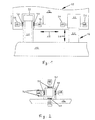
- Figure 1 shows a schematic, partially sectioned Partial view of a crawler track 10 according to the invention with a Middle part 12, on which a cross in 20 a longitudinal direction 18 extending caterpillar 14 with a caterpillar 16 is attached.
- the cross members 20 are each in guides 22 attached to the central part 12 are slidably mounted in a direction of displacement 24.
- the cross member 20 and the guides 22 are each made of one Square steel profile manufactured.
- To adjust one Track width of the crawler track 10 can the crawler 14th in the direction of displacement 24 with the help of hydraulic cylinders, not shown in Figure 1 for clarity are extended and retracted.
- Clamping cylinder 28 with clamping jaws 30.
- the clamping cylinder 28 are with the help of fasteners 32 on the guides 22 attached. This is schematic in the sectional view shown in Figure 2, for clarity only two fasteners 32 are shown. Identical components are given the same reference numerals in FIG. 2 as indicated in Fig. 1.
- the clamping cylinders 28 act from opposite one another Pages in both horizontal and vertical directions on the cross member 20, whereby a particularly stable Tension is achieved.
- a match between Cross member 20 and associated guide 22 is largely as a result avoided. This will be especially useful when working with a vibrating device considerable relief reached.
- the clamping cylinders 28 can in principle be clamped as desired and be relaxed. However, an operating mode is preferred, in which the clamping cylinders 28 are always braced, it is because the crawler carriers 14 are extended or retracted.
Landscapes
- Engineering & Computer Science (AREA)
- Mining & Mineral Resources (AREA)
- Civil Engineering (AREA)
- General Engineering & Computer Science (AREA)
- Structural Engineering (AREA)
- Chemical & Material Sciences (AREA)
- Combustion & Propulsion (AREA)
- Transportation (AREA)
- Mechanical Engineering (AREA)
- Jib Cranes (AREA)
- Body Structure For Vehicles (AREA)
- Placing Or Removing Of Piles Or Sheet Piles, Or Accessories Thereof (AREA)
- Nitrogen And Oxygen Or Sulfur-Condensed Heterocyclic Ring Systems (AREA)
Abstract
Description
- Fig. 1
- eine schematische, teilweise geschnittene Teilansicht eines erfindungsgemäßen Raupenfahrwerks; und
- Fig. 2
- eine Schnittansicht entlang der Linie 2-2 in Figur 1.
Claims (11)
- Raupenfahrwerk, insbesondere für eine Baumaschine, mit einem Mittelteil (12) und zwei Raupenträgern (14) mit je einer Raupenkette (16), wobei die Raupenträger (14) entlang einer Längsrichtung (18) zu beiden Längsseiten des Mittelteiles (12) angeordnet und an Querträgern (20) befestigt sind, die jeweils über mindestens eine Führung (22) an dem Mittelteil (12) in einer Veschieberichtung (24) verschiebbar gelagert sind,
dadurch gekennzeichnet, dass mindestens ein Spannelement (26) vorgesehen ist, mit dem ein Querträger (20) gegenüber seiner Führung (22) quer zur Verschieberichtung (24) verspannbar ist. - Raupenfahrwerk nach Anspruch 1,
dadurch gekennzeichnet, dass die Spannelemente (26) als hydraulisch betätigbare Spannzylinder (28) ausgebildet sind. - Raupenfahrwerk nach Anspruch 2,
dadurch gekennzeichnet, dass bei wenigstens einem der Querträger (20) an gegenüberliegenden Seiten Spannzylinder (26) vorgesehen sind. - Raupenfahrwerk nach einem der Ansprüche 2 oder 3,
dadurch gekennzeichnet, dass die Spannzylinder (26) in vertikaler Richtung
an einer Ober- und einer Unterseite der Querträger (20) angeordnet sind. - Raupenfahrwerk nach einem der Ansprüche 2 bis 4,
dadurch gekennzeichnet, dass pro Querträger (20) jeweils vier Spannzylinder (28) vorgesehen sind. - Raupenfahrwerk nach einem der Ansprüche 2 bis 5,
dadurch gekennzeichnet, dass bei wenigstens einem der Querträger (20) in Verschieberichtung (24) an unterschiedlichen Positionen Spannzylinder (28) vorgesehen sind. - Raupenfahrwerk nach einem der Ansprüche 2 bis 6,
dadurch gekennzeichnet, dass die Spannzylinder (28) Spannbacken (30) aufweisen. - Raupenfahrwerk nach Anspruch 7,
dadurch gekennzeichnet, dass die Spannbacken (30) und/oder die Querträger (20) mit einer Beschichtung und/oder einer Profilierung versehen sind. - Raupenfahrwerk nach einem der Ansprüche 1 bis 8,
dadurch gekennzeichnet, dass ein Führungsholm des Querträgers (20) im Querschnitt eckig, insbesondere viereckig, ausgebildet ist. - Raupenfahrwerk nach einem der Ansprüche 1 bis 9,
dadurch gekennzeichnet, dass jeder Raupenträger (14) an zwei Querträgern (20) befestigt ist. - Raupenfahrwerk nach einem der Ansprüche 1 bis 10,
dadurch gekennzeichnet, dass zum Verschieben der Raupenträger (14) Hydraulikzylinder vorgesehen sind.
Applications Claiming Priority (2)
| Application Number | Priority Date | Filing Date | Title |
|---|---|---|---|
| DE20206970U DE20206970U1 (de) | 2002-05-02 | 2002-05-02 | Raupenfahrwerk, insbesondere für eine Baumaschine |
| DE20206970U | 2002-05-02 |
Publications (2)
| Publication Number | Publication Date |
|---|---|
| EP1359086A1 true EP1359086A1 (de) | 2003-11-05 |
| EP1359086B1 EP1359086B1 (de) | 2006-12-20 |
Family
ID=7970769
Family Applications (1)
| Application Number | Title | Priority Date | Filing Date |
|---|---|---|---|
| EP03008745A Expired - Lifetime EP1359086B1 (de) | 2002-05-02 | 2003-04-17 | Raupenfahrwerk, insbesondere für eine Baumaschine |
Country Status (5)
| Country | Link |
|---|---|
| US (1) | US6796391B2 (de) |
| EP (1) | EP1359086B1 (de) |
| JP (1) | JP4394371B2 (de) |
| CN (1) | CN1251914C (de) |
| DE (2) | DE20206970U1 (de) |
Families Citing this family (2)
| Publication number | Priority date | Publication date | Assignee | Title |
|---|---|---|---|---|
| DE20206970U1 (de) * | 2002-05-02 | 2002-09-12 | Bauer Maschinen GmbH, 86529 Schrobenhausen | Raupenfahrwerk, insbesondere für eine Baumaschine |
| WO2011060824A1 (en) * | 2009-11-19 | 2011-05-26 | Caterpillar Commercial S.A.R.L. | Apparatus for a variable gauge undercarriage |
Citations (4)
| Publication number | Priority date | Publication date | Assignee | Title |
|---|---|---|---|---|
| US3712398A (en) * | 1970-03-19 | 1973-01-23 | Orenstein & Koppel Ag | Hydraulically operable device for changing the track width of track-laying vehicles |
| US5489114A (en) * | 1994-09-29 | 1996-02-06 | Kidde Industries, Inc. | Tie rod extendable and retractable telescopic axle assembly |
| WO1997031813A1 (en) * | 1996-02-29 | 1997-09-04 | Caterpillar Inc. | Apparatus for locking the movable parts of a variable gauge |
| DE20206970U1 (de) * | 2002-05-02 | 2002-09-12 | Bauer Maschinen GmbH, 86529 Schrobenhausen | Raupenfahrwerk, insbesondere für eine Baumaschine |
Family Cites Families (9)
| Publication number | Priority date | Publication date | Assignee | Title |
|---|---|---|---|---|
| US2681231A (en) * | 1952-04-16 | 1954-06-15 | Kondracki Joseph | Track-adjusting means for trench diggers and similar machines |
| US3037571A (en) * | 1959-08-17 | 1962-06-05 | Schield Bantam Company | Wide base crawler |
| DE2047480C3 (de) * | 1970-09-26 | 1979-02-08 | Harnischfeger Gmbh, 4600 Dortmund | Kranunterwagen mit Raupenfahrwerk |
| US3820616A (en) * | 1972-02-03 | 1974-06-28 | American Hoist & Derrick Co | Crawler vehicle with dual extensible side frames |
| US3840095A (en) * | 1974-02-11 | 1974-10-08 | Matson C G | Fluid-pressurizible clamp for mounting vibrators and the like |
| FR2249545A5 (de) * | 1973-10-25 | 1975-05-23 | Poclain Sa | |
| US4431074A (en) * | 1982-01-25 | 1984-02-14 | Fmc Corporation | Crane carbody and lower axle construction |
| US5598896A (en) | 1994-12-02 | 1997-02-04 | Caterpillar Inc. | Variable gage undercarriage arrangement |
| GB0103485D0 (en) * | 2001-02-13 | 2001-03-28 | Powermade Designs Ltd | Clamping system |
-
2002
- 2002-05-02 DE DE20206970U patent/DE20206970U1/de not_active Expired - Lifetime
-
2003
- 2003-04-02 US US10/404,444 patent/US6796391B2/en not_active Expired - Lifetime
- 2003-04-17 DE DE50306010T patent/DE50306010D1/de not_active Expired - Lifetime
- 2003-04-17 EP EP03008745A patent/EP1359086B1/de not_active Expired - Lifetime
- 2003-04-29 CN CN03128452.3A patent/CN1251914C/zh not_active Expired - Fee Related
- 2003-05-02 JP JP2003126849A patent/JP4394371B2/ja not_active Expired - Fee Related
Patent Citations (4)
| Publication number | Priority date | Publication date | Assignee | Title |
|---|---|---|---|---|
| US3712398A (en) * | 1970-03-19 | 1973-01-23 | Orenstein & Koppel Ag | Hydraulically operable device for changing the track width of track-laying vehicles |
| US5489114A (en) * | 1994-09-29 | 1996-02-06 | Kidde Industries, Inc. | Tie rod extendable and retractable telescopic axle assembly |
| WO1997031813A1 (en) * | 1996-02-29 | 1997-09-04 | Caterpillar Inc. | Apparatus for locking the movable parts of a variable gauge |
| DE20206970U1 (de) * | 2002-05-02 | 2002-09-12 | Bauer Maschinen GmbH, 86529 Schrobenhausen | Raupenfahrwerk, insbesondere für eine Baumaschine |
Also Published As
| Publication number | Publication date |
|---|---|
| JP2004001731A (ja) | 2004-01-08 |
| CN1454812A (zh) | 2003-11-12 |
| DE50306010D1 (de) | 2007-02-01 |
| CN1251914C (zh) | 2006-04-19 |
| EP1359086B1 (de) | 2006-12-20 |
| JP4394371B2 (ja) | 2010-01-06 |
| US6796391B2 (en) | 2004-09-28 |
| DE20206970U1 (de) | 2002-09-12 |
| US20030205416A1 (en) | 2003-11-06 |
Similar Documents
| Publication | Publication Date | Title |
|---|---|---|
| AT396097B (de) | Chassis fuer raupenfahrwerke | |
| DE69515809T2 (de) | Fahrgestell mit verstellbarer Spurbreite | |
| DE19957048C1 (de) | Gleitschalungsfertiger | |
| EP2238071B1 (de) | Fahrbare arbeitsmaschine | |
| EP1325861B1 (de) | Raupenfahrwerk | |
| EP2998264A1 (de) | Seitlich abgespannter gittermast | |
| DE102013205888A1 (de) | Fahrbare Arbeitsmaschine, insbesondere Autobetonpumpe und Herstellungsverfahren | |
| EP2088115B1 (de) | Kran | |
| EP3202985B1 (de) | Pontonlaufwerk, pontonfahrschiff und verfahren zum an- und abbauen von pontonfahrschiffen | |
| DE2840800B1 (de) | Kanalbaumaschine | |
| CH615471A5 (de) | ||
| DE102005041255A1 (de) | Transportoptimierter Kranunterwagen | |
| EP0899173B1 (de) | Fahrzeug mit Rahmenabstützung | |
| DE2727655C3 (de) | Fahrbare Grubenausbaueinheit | |
| EP1359086B1 (de) | Raupenfahrwerk, insbesondere für eine Baumaschine | |
| DE2648324A1 (de) | Fahrgestell fuer ein fahrzeug | |
| DE69601651T3 (de) | Ladefläche für Lastkraftwagen oder Anhänger | |
| DE202013001898U1 (de) | Mittel zur Verbreiterung eines Transportmittels sowie Transportmittel | |
| DE2809670C2 (de) | Vorrichtung zur Veränderung der Spurweite von Gleiskettenfahrzeugen | |
| DE102009041045B4 (de) | Fahrbare Arbeitsmaschine für den Bergbau | |
| DE2818612A1 (de) | Tragsystem fuer einen hebekran o.dgl. | |
| DE10354093A1 (de) | Hubgerüst mit Flachriemen als Kraftübertragungsmittel | |
| DE19937252B4 (de) | Abspanneinrichtung für Förder- und/oder Gewinnungsanlagen | |
| DE2417444C3 (de) | Vorrichtung zum Verschieben von Eisenbahngleisen | |
| DE202024101344U1 (de) | Anbaugerät zur Bodenverfestigung und Bagger |
Legal Events
| Date | Code | Title | Description |
|---|---|---|---|
| PUAI | Public reference made under article 153(3) epc to a published international application that has entered the european phase |
Free format text: ORIGINAL CODE: 0009012 |
|
| AK | Designated contracting states |
Kind code of ref document: A1 Designated state(s): AT BE BG CH CY CZ DE DK EE ES FI FR GB GR HU IE IT LI LU MC NL PT RO SE SI SK TR |
|
| AX | Request for extension of the european patent |
Extension state: AL LT LV MK |
|
| 17P | Request for examination filed |
Effective date: 20031230 |
|
| AKX | Designation fees paid |
Designated state(s): DE FI FR GB IT NL |
|
| GRAP | Despatch of communication of intention to grant a patent |
Free format text: ORIGINAL CODE: EPIDOSNIGR1 |
|
| GRAS | Grant fee paid |
Free format text: ORIGINAL CODE: EPIDOSNIGR3 |
|
| GRAA | (expected) grant |
Free format text: ORIGINAL CODE: 0009210 |
|
| AK | Designated contracting states |
Kind code of ref document: B1 Designated state(s): DE FI FR GB IT NL |
|
| REG | Reference to a national code |
Ref country code: GB Ref legal event code: FG4D Free format text: NOT ENGLISH |
|
| REF | Corresponds to: |
Ref document number: 50306010 Country of ref document: DE Date of ref document: 20070201 Kind code of ref document: P |
|
| GBT | Gb: translation of ep patent filed (gb section 77(6)(a)/1977) |
Effective date: 20070207 |
|
| ET | Fr: translation filed | ||
| PLBE | No opposition filed within time limit |
Free format text: ORIGINAL CODE: 0009261 |
|
| STAA | Information on the status of an ep patent application or granted ep patent |
Free format text: STATUS: NO OPPOSITION FILED WITHIN TIME LIMIT |
|
| 26N | No opposition filed |
Effective date: 20070921 |
|
| PGFP | Annual fee paid to national office [announced via postgrant information from national office to epo] |
Ref country code: GB Payment date: 20140410 Year of fee payment: 12 |
|
| GBPC | Gb: european patent ceased through non-payment of renewal fee |
Effective date: 20150417 |
|
| PG25 | Lapsed in a contracting state [announced via postgrant information from national office to epo] |
Ref country code: GB Free format text: LAPSE BECAUSE OF NON-PAYMENT OF DUE FEES Effective date: 20150417 |
|
| REG | Reference to a national code |
Ref country code: FR Ref legal event code: PLFP Year of fee payment: 14 |
|
| REG | Reference to a national code |
Ref country code: FR Ref legal event code: PLFP Year of fee payment: 15 |
|
| REG | Reference to a national code |
Ref country code: DE Ref legal event code: R082 Ref document number: 50306010 Country of ref document: DE Representative=s name: WUNDERLICH & HEIM PATENTANWAELTE PARTNERSCHAFT, DE |
|
| REG | Reference to a national code |
Ref country code: FR Ref legal event code: PLFP Year of fee payment: 16 |
|
| PGFP | Annual fee paid to national office [announced via postgrant information from national office to epo] |
Ref country code: FR Payment date: 20180424 Year of fee payment: 16 |
|
| PG25 | Lapsed in a contracting state [announced via postgrant information from national office to epo] |
Ref country code: FR Free format text: LAPSE BECAUSE OF NON-PAYMENT OF DUE FEES Effective date: 20190430 |
|
| PGFP | Annual fee paid to national office [announced via postgrant information from national office to epo] |
Ref country code: FI Payment date: 20220309 Year of fee payment: 20 |
|
| PGFP | Annual fee paid to national office [announced via postgrant information from national office to epo] |
Ref country code: NL Payment date: 20220324 Year of fee payment: 20 Ref country code: IT Payment date: 20220317 Year of fee payment: 20 |
|
| PGFP | Annual fee paid to national office [announced via postgrant information from national office to epo] |
Ref country code: DE Payment date: 20220307 Year of fee payment: 20 |
|
| REG | Reference to a national code |
Ref country code: DE Ref legal event code: R071 Ref document number: 50306010 Country of ref document: DE |
|
| REG | Reference to a national code |
Ref country code: NL Ref legal event code: MK Effective date: 20230416 |