EP1358927A1 - method and apparatus for mixing gases - Google Patents
method and apparatus for mixing gases Download PDFInfo
- Publication number
- EP1358927A1 EP1358927A1 EP20030006343 EP03006343A EP1358927A1 EP 1358927 A1 EP1358927 A1 EP 1358927A1 EP 20030006343 EP20030006343 EP 20030006343 EP 03006343 A EP03006343 A EP 03006343A EP 1358927 A1 EP1358927 A1 EP 1358927A1
- Authority
- EP
- European Patent Office
- Prior art keywords
- stream
- mixing chamber
- gas
- manifold
- passages
- Prior art date
- Legal status (The legal status is an assumption and is not a legal conclusion. Google has not performed a legal analysis and makes no representation as to the accuracy of the status listed.)
- Granted
Links
- IEDKRPNKQPPDFC-UHFFFAOYSA-N O=NCCC1CCC=CCCC1 Chemical compound O=NCCC1CCC=CCCC1 IEDKRPNKQPPDFC-UHFFFAOYSA-N 0.000 description 1
Images


Classifications
-
- B—PERFORMING OPERATIONS; TRANSPORTING
- B01—PHYSICAL OR CHEMICAL PROCESSES OR APPARATUS IN GENERAL
- B01F—MIXING, e.g. DISSOLVING, EMULSIFYING OR DISPERSING
- B01F23/00—Mixing according to the phases to be mixed, e.g. dispersing or emulsifying
- B01F23/10—Mixing gases with gases
-
- B—PERFORMING OPERATIONS; TRANSPORTING
- B01—PHYSICAL OR CHEMICAL PROCESSES OR APPARATUS IN GENERAL
- B01F—MIXING, e.g. DISSOLVING, EMULSIFYING OR DISPERSING
- B01F25/00—Flow mixers; Mixers for falling materials, e.g. solid particles
- B01F25/30—Injector mixers
- B01F25/31—Injector mixers in conduits or tubes through which the main component flows
- B01F25/313—Injector mixers in conduits or tubes through which the main component flows wherein additional components are introduced in the centre of the conduit
-
- B—PERFORMING OPERATIONS; TRANSPORTING
- B01—PHYSICAL OR CHEMICAL PROCESSES OR APPARATUS IN GENERAL
- B01F—MIXING, e.g. DISSOLVING, EMULSIFYING OR DISPERSING
- B01F25/00—Flow mixers; Mixers for falling materials, e.g. solid particles
- B01F25/30—Injector mixers
- B01F25/31—Injector mixers in conduits or tubes through which the main component flows
- B01F25/314—Injector mixers in conduits or tubes through which the main component flows wherein additional components are introduced at the circumference of the conduit
- B01F25/3142—Injector mixers in conduits or tubes through which the main component flows wherein additional components are introduced at the circumference of the conduit the conduit having a plurality of openings in the axial direction or in the circumferential direction
-
- B—PERFORMING OPERATIONS; TRANSPORTING
- B01—PHYSICAL OR CHEMICAL PROCESSES OR APPARATUS IN GENERAL
- B01F—MIXING, e.g. DISSOLVING, EMULSIFYING OR DISPERSING
- B01F25/00—Flow mixers; Mixers for falling materials, e.g. solid particles
- B01F25/40—Static mixers
- B01F25/42—Static mixers in which the mixing is affected by moving the components jointly in changing directions, e.g. in tubes provided with baffles or obstructions
- B01F25/43—Mixing tubes, e.g. wherein the material is moved in a radial or partly reversed direction
- B01F25/432—Mixing tubes, e.g. wherein the material is moved in a radial or partly reversed direction with means for dividing the material flow into separate sub-flows and for repositioning and recombining these sub-flows; Cross-mixing, e.g. conducting the outer layer of the material nearer to the axis of the tube or vice-versa
- B01F25/4323—Mixing tubes, e.g. wherein the material is moved in a radial or partly reversed direction with means for dividing the material flow into separate sub-flows and for repositioning and recombining these sub-flows; Cross-mixing, e.g. conducting the outer layer of the material nearer to the axis of the tube or vice-versa using elements provided with a plurality of channels or using a plurality of tubes which can either be placed between common spaces or collectors
-
- G—PHYSICS
- G01—MEASURING; TESTING
- G01N—INVESTIGATING OR ANALYSING MATERIALS BY DETERMINING THEIR CHEMICAL OR PHYSICAL PROPERTIES
- G01N1/00—Sampling; Preparing specimens for investigation
- G01N1/02—Devices for withdrawing samples
- G01N1/22—Devices for withdrawing samples in the gaseous state
- G01N1/2247—Sampling from a flowing stream of gas
- G01N1/2252—Sampling from a flowing stream of gas in a vehicle exhaust
-
- G—PHYSICS
- G01—MEASURING; TESTING
- G01N—INVESTIGATING OR ANALYSING MATERIALS BY DETERMINING THEIR CHEMICAL OR PHYSICAL PROPERTIES
- G01N1/00—Sampling; Preparing specimens for investigation
- G01N1/02—Devices for withdrawing samples
- G01N1/22—Devices for withdrawing samples in the gaseous state
- G01N1/2247—Sampling from a flowing stream of gas
- G01N2001/2264—Sampling from a flowing stream of gas with dilution
-
- Y—GENERAL TAGGING OF NEW TECHNOLOGICAL DEVELOPMENTS; GENERAL TAGGING OF CROSS-SECTIONAL TECHNOLOGIES SPANNING OVER SEVERAL SECTIONS OF THE IPC; TECHNICAL SUBJECTS COVERED BY FORMER USPC CROSS-REFERENCE ART COLLECTIONS [XRACs] AND DIGESTS
- Y10—TECHNICAL SUBJECTS COVERED BY FORMER USPC
- Y10T—TECHNICAL SUBJECTS COVERED BY FORMER US CLASSIFICATION
- Y10T137/00—Fluid handling
- Y10T137/8593—Systems
- Y10T137/87571—Multiple inlet with single outlet
- Y10T137/87652—With means to promote mixing or combining of plural fluids
Definitions
- the present invention is directed to a method and an apparatus for mixing streams of gases to form a combined stream.
- the exhaust gases of these engines must be tested or otherwise analyzed for undesirable combustion by-products, such as hydrocarbons, carbon monoxides, sulphates, and/or oxides of nitrogen.
- testing is accomplished by introducing exhaust gases, diluting these exhaust gases with clean air, and obtaining samples after the exhaust gases and dilution air are properly mixed.
- Dilution tunnels are one known type of device for collecting, diluting, cooling, and mixing exhaust gases with filtered, ambient, and conditioned air in a ratio of gas to air for sampling and analyzing.
- a typical dilution tunnel has one inlet for receiving exhaust gases and another inlet for receiving the filtered air.
- An orifice plate is typically placed downstream of the exhaust gas and air inlets in order to induce turbulent flow and facilitate mixing of the exhaust gas and diluting air. Downstream of the orifice plate a probe is located in the tunnel to collect a sample of the mixture for analysis.
- One problem with placing orifice plates, or other obstructions such as inlet pipes, in the stream is that they tend to collect and remove some of the particulate matter from the stream, which distorts the downstream samples.
- abrupt changes in tunnel geometry may also cause particulate matter to collect on the tunnel walls. This particulate matter may build up on the plate or walls over time and then periodically flake off, further distorting the samples taken downstream.
- Full dilution tunnels collect and dilute the entire exhaust gas flow from the engine being tested.
- Current EPA regulations recommend that the dilution tunnels be sized to permit development of turbulent flow (Reynold's number greater than 4000) and obtain a homogeneous mixture of the exhaust and dilution air at the sampling location.
- a typical full dilution tunnel diameter may be on the order of 203 to 610 mm (8 to 24 inches) and a typical tunnel length, which is usually ten times the diameter, may be on the order of 2032 to 6100 mm (80 to 240 inches).
- the tunnel diameter and length is sized to insure proper mixing of the exhaust gas with the diluting air prior to taking the sample.
- the larger the engine displacement the larger the tunnel diameter and tunnel length must be to accommodate the greater flow of exhaust gas.
- dilution tunnels for large displacement engines may be very bulky, even taking up entire rooms.
- U.S. Patent No. 5,090,258 discloses a multiple flow-dividing dilution tunnel system. Dilution air is introduced at one end of the tunnel. Further downstream, a portion of an exhaust gas stream is introduced into the tunnel via an exhaust gas inlet pipe inserted into the stream of dilution air. Further downstream, but proximate the end of the exhaust gas inlet pipe, a plurality of nozzles are inserted into the stream of dilution air/exhaust gas for introducing more dilution air, in this instance, a controlled amount of pressurized dilution air.
- This introduction of pressurized dilution air is used to properly maintain the ratio of the rate of the divided exhaust gas introduced into the dilution tunnel via the exhaust gas inlet pipe to the rate of the total gas introduced into the system, even during pressure loss fluctuations.
- One drawback of this system is that it requires a complex control system for reacting to pressure fluctuations.
- Another drawback is that it also requires a complex system of piping, both for splitting the exhaust gas stream and for introducing the pressurized dilution air.
- a further drawback is that the exhaust inlet pipe is exposed to the dilution air stream prior to the exhaust gas exiting the inlet pipe, causing undesirable cooling of the exhaust gas prior to mixing.
- the disclosed method and apparatus for mixing streams of gases solves one or more of the problems set forth above.
- One aspect of the present invention is directed to a method of mixing a first stream of gas with a second stream of gas.
- the method includes introducing the first stream of gas into a first stream manifold and directing the first stream from the first stream manifold into a mixing chamber via a plurality of first stream passages flow coupled to the mixing chamber.
- the second stream of gas is directed into the mixing chamber via at least one second stream passage flow coupled to a first end of the mixing chamber.
- a combined stream is formed from the first and second streams, gradually converged, and discharged from the mixing chamber through a mixing chamber exit port.
- the present invention is directed to an apparatus for mixing a first and second stream of gas.
- the apparatus includes a first stream manifold configured to receive the first stream of gas, and a first plurality of passages flow coupled to and extending from the first stream manifold.
- a mixing chamber having first and second ends is flow coupled to the first plurality of passages and configured to receive the second stream of gas at the first end.
- the mixing chamber has an exit port at the second end and a cross-section adjacent the second end which gradually converges as the distance to the exit port decreases.
- Fig. 1 shows an apparatus, designated generally by reference number 100, which includes a mixing chamber 30 receiving a first stream 10 and a second stream 20.
- first stream 10 may be either a stream of exhaust gas or a stream of dilution gas
- second stream 20 may be the other of the stream of exhaust gas or dilution gas.
- first stream 10 may be a stream of dilution gas
- second stream 20 may be a stream of exhaust gas.
- mixing chamber 30, which receives both first stream 10 and second stream 20, would receive, in this embodiment, both the stream of exhaust gas and the stream of dilution gas.
- the stream of exhaust gas which may be generated by an engine, such as a diesel engine, contains particulate matter and/or other emissions that are to be measured.
- the stream of dilution gas may be conditioned air, i.e., air that is filtered, heated, cooled, humidified, de-humidified, etc.
- apparatus 100 may include, among other components, first stream manifold 12, passages 14, 24, mixing chamber 30, and secondary mixing region 50.
- Each of these components may be designed and manufactured with no internal protuberances or projections that could collect particulate matter, if any, carried by the first and/or second streams 10, 20.
- the internal wall surfaces of each of these components may be made of smooth materials, such as an electro-polished, passivated, stainless steel or other smooth, relatively non-stick materials, for minimizing the amount of particulate matter that could collect on the walls.
- these components may be assembled in a manner that minimizes the number of wall surfaces upon which the first and second streams 10, 20 impinge or that minimizes the angle of impingement.
- first stream 10 travels through an inlet pipe 11 and enters first stream manifold 12.
- First stream manifold 12 is used to evenly distribute first stream 10 into a plurality of passages 14.
- Passages 14 extend from first stream manifold 12 to mixing chamber 30 and are used to evenly introduce the flow of first stream 10 into mixing chamber 30.
- passages 14 may be sized and configured to allow a well-developed flow to develop within first stream 10 as it flows through these passages.
- a well-developed flow has a steady state mean velocity profile, i.e., a mean velocity profile that does not change with distance in the flow direction. If a straight line passes through the diameter of a well-developed flow, the velocity at a each point of the line would be different.
- the velocity near the walls would be a minimum velocity, for instance, a zero velocity, while the velocity near the center of the passage would be a maximum.
- a well-developed flow generally arises in a long pipe if the flow is not subject to any protrusions, changes in cross-section, or other disturbances.
- passages 14 are depicted as being smooth-walled, relatively thin, straight tubes sufficiently long to develop a well-developed turbulent flow prior to discharging first stream 10 into mixing chamber 30.
- Second stream 20 is shown in Figs. 1 and 2 entering mixing chamber 30 through second stream passage 24. Similar to passages 14, second stream passage 24 may be sized and configured to allow a turbulent flow to form within second stream 20 as it flows through passage 24. Passage 24 may be sized and configured such that, prior to entering mixing chamber 30, the flow of second stream 20 is a well-developed turbulent flow, with no separation at the passage walls. Passage 24 may be a smooth-walled, relatively long, narrow tube having, for example, two rounded ninety-degree bends.
- First stream 10 and second stream 20 are introduced into mixing chamber 30.
- Mixing chamber 30 has a first end 31 and a second end 32 opposite first end 31.
- first end 31 may be a flat wall.
- Both first and second streams 10, 20 are introduced into mixing chamber 30 at first end 31.
- passages 14 and passage 24 do not extend or protrude into mixing chamber, but end substantially flush with the wall of first end 31. This flush configuration allows for even mixing of first stream 10 with second stream 20, and ensures that neither the first stream nor the second stream is in contact with the passages of the other prior to discharging the streams into the mixing chamber. Isolating the first stream passage from the second stream prevents the second stream from prematurely and/or unevenly heating or cooling the first stream.
- isolating the two streams from one another prior to their being discharged into mixing chamber 30 prevents the streams from becoming non-uniform or biased prior to discharge.
- the first stream was a hot exhaust gas stream and the second stream was a cool air stream
- contact between the passages of the hot exhaust gas stream and the cool air stream could cause the undesirable deposition of soot or other particulate matter on the walls of the exhaust gas stream passage due to thermophoretic effects.
- apparatus 100 or individual components of apparatus 100 may be insulated from the surrounding evironment and/or from one another to assist in minimizing thermophoretic effects.
- the plurality of passages 14, which discharge first stream 10 into mixing chamber 30, are symmetrically positioned with respect to the cross-section of mixing chamber 30 and with respect to passage 24, which discharges second stream 20 into mixing chamber 30.
- Four passages 14 are shown, but any number of a plurality of passages may be utilized.
- a single passage 24 is shown, located in the center of first end 31, for discharging second stream 20 into mixing chamber 30. In alternative embodiments, more than one passage 24 may be provided.
- the symmetrical and distributed discharge of first stream 10 into mixing chamber 30 aids in the uniform and efficient mixing of first stream 10 with second stream 20.
- Mixing chamber 30, as best shown in Fig. 2 is a smooth-walled chamber having no internal protuberances or projections, which could collect particulate matter, if any, carried by the first and/or second stream 10, 20.
- the internal wall surfaces 36 of mixing chamber 30 may be formed of a very smooth surface for minimizing the amount of particulate matter that collects on the walls.
- the internal wall surfaces 36 may be electro-polished, passivated, stainless steel or other smooth, relatively non-stick surfaces.
- first stream 10 and second stream 20 lose their separate identities and are combined into a combined stream 40.
- Combined stream 40 exits mixing chamber 30 through an exit port 34 located at second end 32.
- Combined stream 40 need not be a uniformly mixed stream by the time it exits mixing chamber 30 through exit port 34. Rather, combined stream 40 may include both first and second streams 10, 20 in a partially mixed state.
- Second end 32 of mixing chamber 30 may include a portion wherein the cross-section gradually and symmetrically converges or necks down as the distance to exit port 34 decreases.
- a cross-section "gradually converges" when the cross-section becomes smaller and smaller in a series of steps or degrees, as opposed to an abrupt transition between two differently sized openings.
- the converging portion of second end 32 has the shape of a truncated cone. This converging portion may be part of a venturi-type nozzle.
- the gradual convergence of the walls of second end 32 provides a smooth, rather than an abrupt, transition to the reduced diameter of exit port 34. This smooth, gradual convergence is intended to prevent particles from collecting on the walls of end 32.
- the symmetrical configuration of second end 32 as it converges, assists in the uniform mixing of combined stream 40.
- Secondary mixing region 50 is depicted in Fig. 1 as having a short initial section 51 located immediately downstream of mixing chamber 30 and a longer cylindrical section 52 located downstream of section 51.
- the cross-sectional diameter of section 52 is greater than the cross-sectional diameter of section 51.
- a sampling device such as any probe known to persons of ordinary skill in the art, may be located in secondary mixing region 50, such as, for example, adjacent to a downstream end thereof.
- a reservoir box 60 which may be a relatively large-volume chamber, may be flow coupled to secondary mixing region 50 at the downstream end of region 50.
- combined stream 40 exits secondary mixing region 50 and is discharged into reservoir box 60.
- Reservoir box 60 provides a pressure drop in the downstream flow and serves to reduce any flow separation effects that might be induced in combined stream 40 adjacent the downstream end of secondary mixing region 50, while at the same time directing combined stream through a turn.
- Reservoir box 60 may be any chamber, including, for instance a porous baffle (not shown), that provides a pressure drop that reduces undesirable flow separation effects.
- Combined stream 40 as shown in Fig. 1, is then discharged from the system.
- apparatus 100 includes a mixing chamber 30, a first stream manifold 12, a second stream manifold 22, and a secondary mixing region 50.
- First stream manifold 12 may be configured as an annular chamber encircling mixing chamber 30, as shown in Figs. 4 and 5.
- Fig. 4 illustrates an embodiment which is configured to receive two alternative first streams 10a, 10b.
- first stream manifold 12 may receive either first stream 10a or first stream 10b through entrance ports 13a, 13b, respectively, located on opposite sides of annular manifold 12.
- the embodiment illustrated in Fig. 5 is configured to receive only one first stream, first stream 10.
- first stream manifold 12 has only a single entrance port 13 for receiving first stream 10.
- Entrance ports 13, 13a, 13b may include diffuser sections for slowing the flow of first streams 10, 10a, 10b, respectively. Diffuser sections may inhibit the impingement of first streams 10, 10a, 10b on the wall of first stream manifold 12 opposite the entrance ports 13, 13a, 13b, thereby, for instance, inhibiting any particulate matter that may be carried by streams 10, 10a, 10b from collecting or being deposited on the wall of first stream manifold 12.
- First stream manifold 12 may be formed with smooth internal wall surfaces to assist in minimizing the deposition of particulate matter on the walls.
- a plurality of first stream passages 14 are flow coupled to and extend between first stream manifold 12 and mixing chamber 30. As shown in Figs. 4 and 5, passages 14 extend radially between annular manifold 12 and centrally located mixing chamber 30. In this configuration, passages 14 allow first stream 10 to enter mixing chamber 30 adjacent first end 31. Passages 14 need not lie in a plane perpendicular to a central, longitudinal axis of the annular manifold and the mixing chamber. Rather, as shown, passages 14 may be angled out of this perpendicular plane.
- Mixing chamber 30, as best shown in Fig. 5, may have a first end 31, having an entrance port 35 and walls which gradually diverge as the distance from entrance port 35 increases.
- Mixing chamber 30 may also have a second end 32, having an exit port 34 and walls which gradually converge as the distance from exit port 34 decreases.
- Second stream 20 enters second stream manifold 22 prior to entering mixing chamber 30 via entrance port 35.
- Second stream manifold 22 may be an annular manifold similar to annular manifold 12 as shown in Figs. 4 and 5, or second stream manifold 22 may be similar to first manifold 12 as shown in Figs. 1 and 2.
- second stream 20 is discharged from annular manifold 22, via passages 24 into a central tubular region 25, which is flow coupled to entrance port 35 of mixing chamber 30.
- first stream 10 and second stream 20 lose their separate identities and are combined into a combined stream 40, which exits mixing chamber 30 through exit port 34.
- Secondary mixing region 50 is flow coupled to mixing chamber 30 and receives combined stream 40. As shown in Fig. 4, secondary mixing region 50 gradually diverges as the distance from exit port 34 increases. This gradual divergence causes a gradual pressure drop in combined stream 40. Adjacent the downstream end of secondary mixing region 50, a sampling device (not shown) may be located in order to collect samples of a fully mixed combined stream 40.
- the Environmental Protection Agency requires transient emissions tests to be conducted for on-highway diesel engines.
- the EPA regulations (for instance, 40 CFR, Chapter 1, ⁇ 83.1310) require that the raw diesel engine exhaust be mixed or diluted with clean air in order to reduce the overall temperature of the exhaust levels.
- These EPA regulations require good mixing over the entire cross-section of the diluted flow of exhaust at the point where the emission samples are collected.
- the apparatus and method provided may be used for mixing a first gas with a second gas prior to sampling a combined stream of the gases, in order to, for example, efficiently test exhaust gas samples for compliance with the EPA pollution regulations.
- the exhaust pipe of a diesel engine could be flow coupled to passage 24 as shown in Fig. 1. Exhaust gases from the diesel engine flow through passage 24, becoming a well-developed flow, which is introduced into mixing chamber 30. Minimal wall-separation of the exhaust flow is achieved, for instance, by providing two ninety-degree bends in passage 24 in three-dimensions. These bends allow the exhaust stream to be introduced into mixing chamber 30 in a minimal space, while at the same time allowing the exhaust stream flow to straighten and become a well-developed flow very quickly.
- a source of conditioned dilution air could be flow coupled to inlet pipe 11, also as shown in Fig. 1.
- the dilution air flows into manifold 12 and then is distributed through the four passages 14 into mixing chamber 30. As the dilution air travels through passages 14, a well-developed flow is created in each passage, prior to being introduced into mixing chamber 30.
- Passage 24, which carries the exhaust gas, is never in contact with the dilution air stream. Similarly, the exhaust gas stream never contacts passages 14, which carry the dilution air. Isolating these passages from the opposing streams prevents the possibility of pre-cooling the exhaust stream prior to its discharge into mixing chamber 30, which could lead to soot deposition on the walls of passage 24, and also prevents the possibility of the streams losing their well-developed flow profiles. Moreover, isolating these passages from the opposing streams greatly simplifies insulation concerns.
- Apparatus 100 includes components, for instance, passages 14, manifold 12, passage 24, mixing chamber 30, secondary mixing region 50, etc., that have smooth internal walls, i.e., walls having surfaces that are not rough, to minimize the deposition of particulate matter on the internal wall surfaces.
- these components are free of any internal projections, such a inlet pipes, or other structures, such as baffles or orifice plates, extending from the internal walls into the flows. So, for instance, minimal particulate matter from the exhaust gas is deposited on surfaces within mixing chamber 30, because mixing chamber 30 has no projections, edges, or other structure extending into the flow stream.
- smooth, electro-polished, passivated, stainless steel is used to form the internal surfaces of mixing chamber 30 or other components of apparatus 100, the deposition of particulate matter on the internal surfaces of apparatus 100 may be minimized.
- mixing chamber 30 the exhaust gas and the dilution air begin to mix in a uniform manner into a combined stream 40.
- combined stream 40 Prior to exiting mixing chamber 30 through exit port 34, combined stream 40 travels through a converged portion of mixing chamber 30. This converged or necked down portion of mixing chamber 30 causes the velocity and the pressure of combined stream 40 to increase, and facilitates quick and uniform mixing of the combined stream.
- Downstream of mixing chamber 30, combined stream 40 travels through a cylindrical, venturi type, or similar type of secondary mixing region 50 to finalize the uniform mixing of the exhaust gas with the dilution air prior to a portion of the combined stream being collected for sampling purposes.
- apparatus 100 Even for large output engines, such as engines rated between 150 and 750 horsepower, apparatus 100, because of its compact size relative to existing full dilution tunnels, may be designed to fit into the same room that also houses the engine. For instance, apparatus 100 may be designed with pipes being no more than 0.64 meters (24 inches) in diameter. Finally, apparatus 100 may be designed to allow the use of standard pipes and standard-pipe fittings, thus, minimizing the use of specially built parts and substantially decreasing the cost of manufacture.
- a first test chamber may be located adjacent apparatus 100 and may contain a first stream source (not shown).
- a diesel engine emitting a first stream 10a of an exhaust gas may be the first stream source.
- This first stream source may be flow coupled to entrance port 13a.
- a second test chamber (not shown) with a second stream source (not shown) may be located on the other side of apparatus 100.
- Second stream source may be a second diesel engine emitting a stream of exhaust gas as alternative first stream 10b. This second exhaust gas source producing alternative first stream 10b may be flow coupled to entrance port 13b.
- the embodiment with two entrance ports may service two separate test chambers.
- entrance port 13a may be opened, allowing first stream 10a to flow into manifold 12, while entrance port 13b may be closed, blocking the flow of alternative first stream 10b into manifold 12.
- entrance port 13b may be opened and entrance port 13a may be closed.
Landscapes
- Chemical & Material Sciences (AREA)
- Chemical Kinetics & Catalysis (AREA)
- Life Sciences & Earth Sciences (AREA)
- Health & Medical Sciences (AREA)
- Physics & Mathematics (AREA)
- Engineering & Computer Science (AREA)
- Biomedical Technology (AREA)
- Molecular Biology (AREA)
- Dispersion Chemistry (AREA)
- Analytical Chemistry (AREA)
- Biochemistry (AREA)
- General Health & Medical Sciences (AREA)
- General Physics & Mathematics (AREA)
- Immunology (AREA)
- Pathology (AREA)
- Sampling And Sample Adjustment (AREA)
- Testing Of Engines (AREA)
Abstract
Description
- The present invention is directed to a method and an apparatus for mixing streams of gases to form a combined stream.
- The federal government and other authorities regulate allowable exhaust emissions from gasoline and diesel engines for automobiles, trucks, and other vehicles, such as off-road construction or agricultural vehicles, in an effort to reduce pollution. In order to ensure compliance with these regulations, the exhaust gases of these engines must be tested or otherwise analyzed for undesirable combustion by-products, such as hydrocarbons, carbon monoxides, sulphates, and/or oxides of nitrogen. In general, testing is accomplished by introducing exhaust gases, diluting these exhaust gases with clean air, and obtaining samples after the exhaust gases and dilution air are properly mixed.
- Dilution tunnels are one known type of device for collecting, diluting, cooling, and mixing exhaust gases with filtered, ambient, and conditioned air in a ratio of gas to air for sampling and analyzing. At one end, a typical dilution tunnel has one inlet for receiving exhaust gases and another inlet for receiving the filtered air. An orifice plate is typically placed downstream of the exhaust gas and air inlets in order to induce turbulent flow and facilitate mixing of the exhaust gas and diluting air. Downstream of the orifice plate a probe is located in the tunnel to collect a sample of the mixture for analysis. One problem with placing orifice plates, or other obstructions such as inlet pipes, in the stream is that they tend to collect and remove some of the particulate matter from the stream, which distorts the downstream samples. Moreover, abrupt changes in tunnel geometry may also cause particulate matter to collect on the tunnel walls. This particulate matter may build up on the plate or walls over time and then periodically flake off, further distorting the samples taken downstream.
- Full dilution tunnels collect and dilute the entire exhaust gas flow from the engine being tested. Current EPA regulations recommend that the dilution tunnels be sized to permit development of turbulent flow (Reynold's number greater than 4000) and obtain a homogeneous mixture of the exhaust and dilution air at the sampling location. Depending upon the engine displacement, in order to meet this requirement, a typical full dilution tunnel diameter may be on the order of 203 to 610 mm (8 to 24 inches) and a typical tunnel length, which is usually ten times the diameter, may be on the order of 2032 to 6100 mm (80 to 240 inches). The tunnel diameter and length is sized to insure proper mixing of the exhaust gas with the diluting air prior to taking the sample. The larger the engine displacement, the larger the tunnel diameter and tunnel length must be to accommodate the greater flow of exhaust gas. Thus, dilution tunnels for large displacement engines may be very bulky, even taking up entire rooms.
- U.S. Patent No. 5,090,258 discloses a multiple flow-dividing dilution tunnel system. Dilution air is introduced at one end of the tunnel. Further downstream, a portion of an exhaust gas stream is introduced into the tunnel via an exhaust gas inlet pipe inserted into the stream of dilution air. Further downstream, but proximate the end of the exhaust gas inlet pipe, a plurality of nozzles are inserted into the stream of dilution air/exhaust gas for introducing more dilution air, in this instance, a controlled amount of pressurized dilution air. This introduction of pressurized dilution air is used to properly maintain the ratio of the rate of the divided exhaust gas introduced into the dilution tunnel via the exhaust gas inlet pipe to the rate of the total gas introduced into the system, even during pressure loss fluctuations. One drawback of this system is that it requires a complex control system for reacting to pressure fluctuations. Another drawback is that it also requires a complex system of piping, both for splitting the exhaust gas stream and for introducing the pressurized dilution air. A further drawback is that the exhaust inlet pipe is exposed to the dilution air stream prior to the exhaust gas exiting the inlet pipe, causing undesirable cooling of the exhaust gas prior to mixing.
- The disclosed method and apparatus for mixing streams of gases solves one or more of the problems set forth above.
- One aspect of the present invention is directed to a method of mixing a first stream of gas with a second stream of gas. The method includes introducing the first stream of gas into a first stream manifold and directing the first stream from the first stream manifold into a mixing chamber via a plurality of first stream passages flow coupled to the mixing chamber. The second stream of gas is directed into the mixing chamber via at least one second stream passage flow coupled to a first end of the mixing chamber. A combined stream is formed from the first and second streams, gradually converged, and discharged from the mixing chamber through a mixing chamber exit port.
- In another aspect, the present invention is directed to an apparatus for mixing a first and second stream of gas. The apparatus includes a first stream manifold configured to receive the first stream of gas, and a first plurality of passages flow coupled to and extending from the first stream manifold. A mixing chamber having first and second ends is flow coupled to the first plurality of passages and configured to receive the second stream of gas at the first end. The mixing chamber has an exit port at the second end and a cross-section adjacent the second end which gradually converges as the distance to the exit port decreases.
- It is to be understood that both the foregoing general description and the following detailed description are exemplary and explanatory only and are not restrictive of the invention, as claimed.
- The accompanying drawings, which are incorporated in and constitute a part of this specification, illustrate exemplary embodiments of the invention and together with the description, serve to explain the principles of the invention. In the drawings:
- Fig. 1 is a schematic and diagrammatic illustration of an embodiment of an apparatus for mixing gases;
- Fig. 2 is schematic cross-sectional illustration of a portion of the
apparatus of Fig. 1 rotated 45 degrees so that at least two
passages 14 andpassage 24 lie in the viewing plane; - Fig. 3 is a cross-section of the apparatus of Fig. 2 taken at section A-A;
- Fig. 4 is a schematic and diagrammatic illustration of another embodiment of an apparatus for mixing gases; and
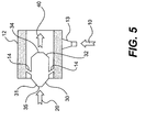
- Fig. 5 is schematic and diagrammatic illustration of a further embodiment of an apparatus for mixing gases.
-
- Fig. 1 shows an apparatus, designated generally by
reference number 100, which includes amixing chamber 30 receiving afirst stream 10 and asecond stream 20. In one embodiment,first stream 10 may be either a stream of exhaust gas or a stream of dilution gas, andsecond stream 20 may be the other of the stream of exhaust gas or dilution gas. For example,first stream 10 may be a stream of dilution gas andsecond stream 20 may be a stream of exhaust gas. Thus, mixingchamber 30, which receives bothfirst stream 10 andsecond stream 20, would receive, in this embodiment, both the stream of exhaust gas and the stream of dilution gas. The stream of exhaust gas, which may be generated by an engine, such as a diesel engine, contains particulate matter and/or other emissions that are to be measured. The stream of dilution gas may be conditioned air, i.e., air that is filtered, heated, cooled, humidified, de-humidified, etc. - In one embodiment, as shown in Fig. 1,
apparatus 100 may include, among other components,first stream manifold 12,passages mixing chamber 30, andsecondary mixing region 50. Each of these components may be designed and manufactured with no internal protuberances or projections that could collect particulate matter, if any, carried by the first and/orsecond streams second streams - As shown in Figs. 1 and 2, prior to entering
mixing chamber 30,first stream 10 travels through aninlet pipe 11 and entersfirst stream manifold 12.First stream manifold 12 is used to evenly distributefirst stream 10 into a plurality ofpassages 14.Passages 14 extend fromfirst stream manifold 12 to mixingchamber 30 and are used to evenly introduce the flow offirst stream 10 intomixing chamber 30. Additionally,passages 14 may be sized and configured to allow a well-developed flow to develop withinfirst stream 10 as it flows through these passages. A well-developed flow has a steady state mean velocity profile, i.e., a mean velocity profile that does not change with distance in the flow direction. If a straight line passes through the diameter of a well-developed flow, the velocity at a each point of the line would be different. The velocity near the walls would be a minimum velocity, for instance, a zero velocity, while the velocity near the center of the passage would be a maximum. A well-developed flow generally arises in a long pipe if the flow is not subject to any protrusions, changes in cross-section, or other disturbances. For example, in Fig. 1,passages 14 are depicted as being smooth-walled, relatively thin, straight tubes sufficiently long to develop a well-developed turbulent flow prior to dischargingfirst stream 10 into mixingchamber 30. -
Second stream 20 is shown in Figs. 1 and 2entering mixing chamber 30 throughsecond stream passage 24. Similar topassages 14,second stream passage 24 may be sized and configured to allow a turbulent flow to form withinsecond stream 20 as it flows throughpassage 24.Passage 24 may be sized and configured such that, prior to entering mixingchamber 30, the flow ofsecond stream 20 is a well-developed turbulent flow, with no separation at the passage walls.Passage 24 may be a smooth-walled, relatively long, narrow tube having, for example, two rounded ninety-degree bends. -
First stream 10 andsecond stream 20 are introduced into mixingchamber 30. Mixingchamber 30 has afirst end 31 and asecond end 32 oppositefirst end 31. As shown in Figs. 2 and 3,first end 31 may be a flat wall. Both first andsecond streams chamber 30 atfirst end 31. As best shown in Fig. 2,passages 14 andpassage 24 do not extend or protrude into mixing chamber, but end substantially flush with the wall offirst end 31. This flush configuration allows for even mixing offirst stream 10 withsecond stream 20, and ensures that neither the first stream nor the second stream is in contact with the passages of the other prior to discharging the streams into the mixing chamber. Isolating the first stream passage from the second stream prevents the second stream from prematurely and/or unevenly heating or cooling the first stream. Moreover, isolating the two streams from one another prior to their being discharged into mixingchamber 30 prevents the streams from becoming non-uniform or biased prior to discharge. For example, if the first stream was a hot exhaust gas stream and the second stream was a cool air stream, then contact between the passages of the hot exhaust gas stream and the cool air stream could cause the undesirable deposition of soot or other particulate matter on the walls of the exhaust gas stream passage due to thermophoretic effects. In addition,apparatus 100 or individual components ofapparatus 100 may be insulated from the surrounding evironment and/or from one another to assist in minimizing thermophoretic effects. - As best shown in Fig. 3, the plurality of
passages 14, which dischargefirst stream 10 into mixingchamber 30, are symmetrically positioned with respect to the cross-section of mixingchamber 30 and with respect topassage 24, which dischargessecond stream 20 into mixingchamber 30. Fourpassages 14 are shown, but any number of a plurality of passages may be utilized. Asingle passage 24 is shown, located in the center offirst end 31, for dischargingsecond stream 20 into mixingchamber 30. In alternative embodiments, more than onepassage 24 may be provided. The symmetrical and distributed discharge offirst stream 10 into mixingchamber 30 aids in the uniform and efficient mixing offirst stream 10 withsecond stream 20. - Mixing
chamber 30, as best shown in Fig. 2, is a smooth-walled chamber having no internal protuberances or projections, which could collect particulate matter, if any, carried by the first and/orsecond stream chamber 30 may be formed of a very smooth surface for minimizing the amount of particulate matter that collects on the walls. For instance, the internal wall surfaces 36 may be electro-polished, passivated, stainless steel or other smooth, relatively non-stick surfaces. - Within mixing
chamber 30,first stream 10 andsecond stream 20 lose their separate identities and are combined into a combinedstream 40. Combinedstream 40exits mixing chamber 30 through anexit port 34 located atsecond end 32. Combinedstream 40 need not be a uniformly mixed stream by the time it exits mixingchamber 30 throughexit port 34. Rather, combinedstream 40 may include both first andsecond streams -
Second end 32 of mixingchamber 30 may include a portion wherein the cross-section gradually and symmetrically converges or necks down as the distance to exitport 34 decreases. A cross-section "gradually converges" when the cross-section becomes smaller and smaller in a series of steps or degrees, as opposed to an abrupt transition between two differently sized openings. As shown in Figs. 1 and 2, the converging portion ofsecond end 32 has the shape of a truncated cone. This converging portion may be part of a venturi-type nozzle. The gradual convergence of the walls ofsecond end 32 provides a smooth, rather than an abrupt, transition to the reduced diameter ofexit port 34. This smooth, gradual convergence is intended to prevent particles from collecting on the walls ofend 32. Moreover, the symmetrical configuration ofsecond end 32, as it converges, assists in the uniform mixing of combinedstream 40. - As best shown in Fig. 1, downstream of mixing
chamber 30, combinedstream 40 may enter asecondary mixing region 50.Secondary mixing region 50 is depicted in Fig. 1 as having a shortinitial section 51 located immediately downstream of mixingchamber 30 and a longercylindrical section 52 located downstream ofsection 51. The cross-sectional diameter ofsection 52 is greater than the cross-sectional diameter ofsection 51. An abrupt enlargement of the cross-sections, as shown in Fig. 1, may be advantageous because of manufacturing considerations. The abrupt enlargement may also enhance mixing. - Within
secondary mixing region 50, uniform mixing, such as required for testing, of combinedstream 40 may be achieved. A sampling device (not shown), such as any probe known to persons of ordinary skill in the art, may be located insecondary mixing region 50, such as, for example, adjacent to a downstream end thereof. - Downstream of
secondary mixing region 50, combinedstream 40 may be directed through a turn, for example, around a corner, to minimize the total length of the system. However, turning the stream may induce undesirable separation effects in combinedstream 40 upstream of the turn, i.e., where the sampling probe may be located. Areservoir box 60, which may be a relatively large-volume chamber, may be flow coupled tosecondary mixing region 50 at the downstream end ofregion 50. As shown in Fig. 1, combinedstream 40 exitssecondary mixing region 50 and is discharged intoreservoir box 60.Reservoir box 60 provides a pressure drop in the downstream flow and serves to reduce any flow separation effects that might be induced in combinedstream 40 adjacent the downstream end ofsecondary mixing region 50, while at the same time directing combined stream through a turn.Reservoir box 60 may be any chamber, including, for instance a porous baffle (not shown), that provides a pressure drop that reduces undesirable flow separation effects. Combinedstream 40, as shown in Fig. 1, is then discharged from the system. - A second embodiment of an apparatus for mixing gases is illustrated in Fig. 4 and is also designated generally by
reference number 100. As shown in Fig. 4,apparatus 100 includes a mixingchamber 30, afirst stream manifold 12, asecond stream manifold 22, and asecondary mixing region 50. -
First stream manifold 12 may be configured as an annular chamber encircling mixingchamber 30, as shown in Figs. 4 and 5. Fig. 4 illustrates an embodiment which is configured to receive two alternativefirst streams first stream manifold 12 may receive eitherfirst stream 10a orfirst stream 10b throughentrance ports annular manifold 12. Alternatively, the embodiment illustrated in Fig. 5 is configured to receive only one first stream,first stream 10. As shown in Fig. 5,first stream manifold 12 has only asingle entrance port 13 for receivingfirst stream 10. -
Entrance ports first streams first streams first stream manifold 12 opposite theentrance ports streams first stream manifold 12.First stream manifold 12 may be formed with smooth internal wall surfaces to assist in minimizing the deposition of particulate matter on the walls. - A plurality of
first stream passages 14 are flow coupled to and extend betweenfirst stream manifold 12 and mixingchamber 30. As shown in Figs. 4 and 5,passages 14 extend radially betweenannular manifold 12 and centrally located mixingchamber 30. In this configuration,passages 14 allowfirst stream 10 to enter mixingchamber 30 adjacentfirst end 31.Passages 14 need not lie in a plane perpendicular to a central, longitudinal axis of the annular manifold and the mixing chamber. Rather, as shown,passages 14 may be angled out of this perpendicular plane. - Mixing
chamber 30, as best shown in Fig. 5, may have afirst end 31, having anentrance port 35 and walls which gradually diverge as the distance fromentrance port 35 increases. Mixingchamber 30 may also have asecond end 32, having anexit port 34 and walls which gradually converge as the distance fromexit port 34 decreases. -
Second stream 20 enterssecond stream manifold 22 prior to entering mixingchamber 30 viaentrance port 35.Second stream manifold 22 may be an annular manifold similar toannular manifold 12 as shown in Figs. 4 and 5, orsecond stream manifold 22 may be similar tofirst manifold 12 as shown in Figs. 1 and 2. As shown in Figs. 4 and 5,second stream 20 is discharged fromannular manifold 22, viapassages 24 into a centraltubular region 25, which is flow coupled toentrance port 35 of mixingchamber 30. - Within mixing
chamber 30 of Figs. 4 and 5, as with mixingchamber 30 of Figs. 1 and 2,first stream 10 andsecond stream 20 lose their separate identities and are combined into a combinedstream 40, which exits mixingchamber 30 throughexit port 34.Secondary mixing region 50 is flow coupled to mixingchamber 30 and receives combinedstream 40. As shown in Fig. 4,secondary mixing region 50 gradually diverges as the distance fromexit port 34 increases. This gradual divergence causes a gradual pressure drop in combinedstream 40. Adjacent the downstream end ofsecondary mixing region 50, a sampling device (not shown) may be located in order to collect samples of a fully mixed combinedstream 40. - The Environmental Protection Agency (EPA) requires transient emissions tests to be conducted for on-highway diesel engines. When utilizing a full dilution tunnel system, the EPA regulations (for instance, 40 CFR, Chapter 1, § 83.1310) require that the raw diesel engine exhaust be mixed or diluted with clean air in order to reduce the overall temperature of the exhaust levels. These EPA regulations require good mixing over the entire cross-section of the diluted flow of exhaust at the point where the emission samples are collected.
- The apparatus and method provided may be used for mixing a first gas with a second gas prior to sampling a combined stream of the gases, in order to, for example, efficiently test exhaust gas samples for compliance with the EPA pollution regulations. In one exemplary use, the exhaust pipe of a diesel engine could be flow coupled to
passage 24 as shown in Fig. 1. Exhaust gases from the diesel engine flow throughpassage 24, becoming a well-developed flow, which is introduced into mixingchamber 30. Minimal wall-separation of the exhaust flow is achieved, for instance, by providing two ninety-degree bends inpassage 24 in three-dimensions. These bends allow the exhaust stream to be introduced into mixingchamber 30 in a minimal space, while at the same time allowing the exhaust stream flow to straighten and become a well-developed flow very quickly. - A source of conditioned dilution air could be flow coupled to
inlet pipe 11, also as shown in Fig. 1. The dilution air flows intomanifold 12 and then is distributed through the fourpassages 14 into mixingchamber 30. As the dilution air travels throughpassages 14, a well-developed flow is created in each passage, prior to being introduced into mixingchamber 30. -
Passage 24, which carries the exhaust gas, is never in contact with the dilution air stream. Similarly, the exhaust gas stream nevercontacts passages 14, which carry the dilution air. Isolating these passages from the opposing streams prevents the possibility of pre-cooling the exhaust stream prior to its discharge into mixingchamber 30, which could lead to soot deposition on the walls ofpassage 24, and also prevents the possibility of the streams losing their well-developed flow profiles. Moreover, isolating these passages from the opposing streams greatly simplifies insulation concerns. -
Apparatus 100 includes components, for instance,passages 14,manifold 12,passage 24, mixingchamber 30,secondary mixing region 50, etc., that have smooth internal walls, i.e., walls having surfaces that are not rough, to minimize the deposition of particulate matter on the internal wall surfaces. In addition, these components are free of any internal projections, such a inlet pipes, or other structures, such as baffles or orifice plates, extending from the internal walls into the flows. So, for instance, minimal particulate matter from the exhaust gas is deposited on surfaces within mixingchamber 30, because mixingchamber 30 has no projections, edges, or other structure extending into the flow stream. Moreover, if smooth, electro-polished, passivated, stainless steel is used to form the internal surfaces of mixingchamber 30 or other components ofapparatus 100, the deposition of particulate matter on the internal surfaces ofapparatus 100 may be minimized. - Within mixing
chamber 30, the exhaust gas and the dilution air begin to mix in a uniform manner into a combinedstream 40. Prior to exiting mixingchamber 30 throughexit port 34, combinedstream 40 travels through a converged portion of mixingchamber 30. This converged or necked down portion of mixingchamber 30 causes the velocity and the pressure of combinedstream 40 to increase, and facilitates quick and uniform mixing of the combined stream. Downstream of mixingchamber 30, combinedstream 40 travels through a cylindrical, venturi type, or similar type ofsecondary mixing region 50 to finalize the uniform mixing of the exhaust gas with the dilution air prior to a portion of the combined stream being collected for sampling purposes. - Even for large output engines, such as engines rated between 150 and 750 horsepower,
apparatus 100, because of its compact size relative to existing full dilution tunnels, may be designed to fit into the same room that also houses the engine. For instance,apparatus 100 may be designed with pipes being no more than 0.64 meters (24 inches) in diameter. Finally,apparatus 100 may be designed to allow the use of standard pipes and standard-pipe fittings, thus, minimizing the use of specially built parts and substantially decreasing the cost of manufacture. - The disclosed system may also be utilized with dual test cells, thereby providing an even more compact and efficient system. As an example of the use of the embodiment shown in Fig. 4, a first test chamber (not shown) may be located
adjacent apparatus 100 and may contain a first stream source (not shown). For instance, a diesel engine emitting afirst stream 10a of an exhaust gas may be the first stream source. This first stream source may be flow coupled toentrance port 13a. A second test chamber (not shown) with a second stream source (not shown) may be located on the other side ofapparatus 100. Second stream source may be a second diesel engine emitting a stream of exhaust gas as alternativefirst stream 10b. This second exhaust gas source producing alternativefirst stream 10b may be flow coupled toentrance port 13b. Thus, the embodiment with two entrance ports, shown in Fig. 4, may service two separate test chambers. In a first test,entrance port 13a may be opened, allowingfirst stream 10a to flow intomanifold 12, whileentrance port 13b may be closed, blocking the flow of alternativefirst stream 10b intomanifold 12. In a subsequent test,entrance port 13b may be opened andentrance port 13a may be closed. - It will be apparent to persons of ordinary skill in the art that various modifications and variations can be made in the method and apparatus for mixing gases of the present invention without departing from the scope or spirit of the invention. Additionally, other embodiments of the invention may be apparent to persons of ordinary skill in the art from consideration of the specification and practice of the invention disclosed herein. It is intended that the specification and examples be considered as exemplary only, with a true scope and spirit of the invention being indicated by the following claims and their equivalents.
Claims (10)
- A method of mixing a first stream of gas with a second stream of gas, comprising:introducing a first stream (10) of gas into a first stream manifold (12);directing the first stream (10) from the first stream manifold (12) into a mixing chamber (30) via a plurality of first stream passages (14) flow coupled to the mixing chamber (30);directing a second stream (20) of gas into the mixing chamber (30) via at least one second stream passage (24) flow coupled to a first end of the mixing chamber (30);forming a combined stream (40) from the first and second streams (10, 20);gradually converging the combined stream (40); anddischarging the converged combined stream (40) from the mixing chamber (30) through a mixing chamber exit port (34).
- The method of claim 1, further including:introducing the second stream (20) into a second stream manifold (22), and wherein directing the second stream (20) includes directing the second stream (20) from the second stream manifold (22) via a plurality of second stream passages (24) flow coupled to the mixing chamber (30).
- The method of claim 1, further including:developing a substantially well-developed flow of the first stream (10) within the plurality of first stream passages (14).
- The method of claim 3, further including:developing a substantially well-developed flow of the second stream (20) within the at least one second stream passage (24).
- The method of claim 1, wherein the first stream (10) is one of a stream of dilution air and a stream of exhaust gas from an engine, and the second stream (20) is the other of the stream of dilution air and the stream of exhaust gas from an engine.
- An apparatus for mixing a first and a second stream of gas, comprising:a first stream manifold (12) configured to receive the first stream (10) of gas;a first plurality of passages (14) flow coupled to and extending from the first stream manifold (12); anda mixing chamber (30) having first and second ends (31, 32), the mixing chamber (30) flow coupled to the first plurality of passages (14) and configure to receive the second stream (20) of gas at the first end (31), the mixing chamber (30) having an exit port (34) at the second end (32) and a cross-section adjacent the second end (32) which gradually converges as the distance to the exit port (34) decreases.
- The apparatus of claim 6, further including:a secondary mixing region (50) flow coupled to the mixing chamber (30) downstream of the exit port (34); anda reservoir box (60) flow coupled to the secondary mixing region (50) at an end opposite the end which is flow coupled to the exit port (34).
- The apparatus of claim 6, wherein the mixing chamber (30) has internal wall surfaces (36) formed of electro-polished, passivated, stainless steel and no projections extending inwardly from the internal wall surfaces (36).
- The apparatus of claim 6, further including:a second stream manifold (22) flow coupled to the other of the stream of dilution gas and the stream of exhaust gas; anda second plurality of passages (24) flow coupled to and extending between the second stream manifold (22) and the mixing chamber (30), wherein the first and second stream manifolds (12, 22) are annular chambers.
- The apparatus of claim 6, wherein the first and second plurality of passages (14, 24) do not substantially extend into the mixing chamber (30).
Applications Claiming Priority (2)
| Application Number | Priority Date | Filing Date | Title |
|---|---|---|---|
| US137370 | 2002-05-03 | ||
| US10/137,370 US6684719B2 (en) | 2002-05-03 | 2002-05-03 | Method and apparatus for mixing gases |
Publications (2)
| Publication Number | Publication Date |
|---|---|
| EP1358927A1 true EP1358927A1 (en) | 2003-11-05 |
| EP1358927B1 EP1358927B1 (en) | 2005-11-16 |
Family
ID=29215696
Family Applications (1)
| Application Number | Title | Priority Date | Filing Date |
|---|---|---|---|
| EP03006343A Expired - Lifetime EP1358927B1 (en) | 2002-05-03 | 2003-03-20 | method and apparatus for mixing gases |
Country Status (4)
| Country | Link |
|---|---|
| US (3) | US6684719B2 (en) |
| EP (1) | EP1358927B1 (en) |
| JP (1) | JP2004004058A (en) |
| DE (1) | DE60302275T2 (en) |
Cited By (3)
| Publication number | Priority date | Publication date | Assignee | Title |
|---|---|---|---|---|
| CN102527217A (en) * | 2011-12-23 | 2012-07-04 | 西安航天动力研究所 | SNCR (Selective Non-Catalytic Reduction) denitration wall jet apparatus |
| EP1890125B1 (en) * | 2005-06-09 | 2018-11-28 | Horiba, Ltd. | Exhaust gas dilution device |
| CN115298531A (en) * | 2020-03-26 | 2022-11-04 | 株式会社堀场制作所 | Diluter, analysis system and analysis method |
Families Citing this family (312)
| Publication number | Priority date | Publication date | Assignee | Title |
|---|---|---|---|---|
| FR2815549B1 (en) * | 2000-10-19 | 2003-01-03 | Air Liquide | INSTALLATION AND PROCEDURE FOR DISCHARGING RESIDUAL GASES FROM AIR DISTILLATION OR LIQUEFACTION UNITS |
| US6684719B2 (en) * | 2002-05-03 | 2004-02-03 | Caterpillar Inc | Method and apparatus for mixing gases |
| US7044009B2 (en) * | 2002-05-20 | 2006-05-16 | Caterpillar Inc. | Dilution tunnel |
| GB0303470D0 (en) * | 2003-02-14 | 2003-03-19 | Malvern Instr Ltd | Dilution system and method |
| US7482705B2 (en) * | 2003-05-12 | 2009-01-27 | Piercey Iii Gerald S | Generator support plenum |
| EP1687611B1 (en) * | 2003-10-30 | 2012-05-23 | Avl North America Inc. | Particulate deposit avoidance and probe positioning |
| US20080129053A1 (en) * | 2004-05-12 | 2008-06-05 | Piercey Gerald S | Engine-generator set |
| EP1771385B1 (en) * | 2004-07-26 | 2010-09-15 | Frank Reiner Kolb | Hydrodynamic homogenization |
| GB0507349D0 (en) * | 2005-04-12 | 2005-05-18 | Malvern Instr Ltd | Dilution apparatus and method |
| US7299690B2 (en) * | 2006-04-26 | 2007-11-27 | Caterpillar Inc. | Particulate sampling system and method |
| US7669411B2 (en) * | 2006-05-10 | 2010-03-02 | Caterpillar Inc. | Cooling device |
| US7587950B2 (en) * | 2006-09-11 | 2009-09-15 | Cummins Filtration Ip Inc. | Source dilution sampling system for emissions analysis |
| KR20110046867A (en) * | 2009-10-29 | 2011-05-06 | 삼성전자주식회사 | Microfluidic device including gas providing unit, liquid mixing method and emulsion formation method using same |
| US20130023129A1 (en) | 2011-07-20 | 2013-01-24 | Asm America, Inc. | Pressure transmitter for a semiconductor processing environment |
| US9574268B1 (en) | 2011-10-28 | 2017-02-21 | Asm America, Inc. | Pulsed valve manifold for atomic layer deposition |
| DE102012102137A1 (en) * | 2012-03-14 | 2013-09-19 | Avl Emission Test Systems Gmbh | Plant for taking exhaust gas samples from internal combustion engines |
| US10232324B2 (en) * | 2012-07-12 | 2019-03-19 | Applied Materials, Inc. | Gas mixing apparatus |
| US8757133B2 (en) | 2012-08-27 | 2014-06-24 | Cummins Intellectual Property, Inc. | Gaseous fuel and intake air mixer for internal combustion engine |
| US8950383B2 (en) | 2012-08-27 | 2015-02-10 | Cummins Intellectual Property, Inc. | Gaseous fuel mixer for internal combustion engine |
| US10714315B2 (en) | 2012-10-12 | 2020-07-14 | Asm Ip Holdings B.V. | Semiconductor reaction chamber showerhead |
| JP5933429B2 (en) * | 2012-12-28 | 2016-06-08 | 株式会社堀場エステック | Fluid mixing element |
| US20160376700A1 (en) | 2013-02-01 | 2016-12-29 | Asm Ip Holding B.V. | System for treatment of deposition reactor |
| US9151495B1 (en) * | 2013-04-19 | 2015-10-06 | The Archer Company, Inc. | Method for reducing volatile organic compounds from gases with hydrocarbons |
| US10683571B2 (en) * | 2014-02-25 | 2020-06-16 | Asm Ip Holding B.V. | Gas supply manifold and method of supplying gases to chamber using same |
| US11015245B2 (en) | 2014-03-19 | 2021-05-25 | Asm Ip Holding B.V. | Gas-phase reactor and system having exhaust plenum and components thereof |
| US10858737B2 (en) | 2014-07-28 | 2020-12-08 | Asm Ip Holding B.V. | Showerhead assembly and components thereof |
| US10941490B2 (en) | 2014-10-07 | 2021-03-09 | Asm Ip Holding B.V. | Multiple temperature range susceptor, assembly, reactor and system including the susceptor, and methods of using the same |
| US10276355B2 (en) | 2015-03-12 | 2019-04-30 | Asm Ip Holding B.V. | Multi-zone reactor, system including the reactor, and method of using the same |
| KR20160147482A (en) * | 2015-06-15 | 2016-12-23 | 삼성전자주식회사 | Apparatus for manufacturing Semiconductor Devices Having a Gas Mixing Part |
| US10458018B2 (en) | 2015-06-26 | 2019-10-29 | Asm Ip Holding B.V. | Structures including metal carbide material, devices including the structures, and methods of forming same |
| US10188996B2 (en) * | 2015-10-02 | 2019-01-29 | Adamis Pharmaceuticals Corporation | Powder mixing apparatus and method of use |
| US10211308B2 (en) | 2015-10-21 | 2019-02-19 | Asm Ip Holding B.V. | NbMC layers |
| US11139308B2 (en) | 2015-12-29 | 2021-10-05 | Asm Ip Holding B.V. | Atomic layer deposition of III-V compounds to form V-NAND devices |
| US10529554B2 (en) | 2016-02-19 | 2020-01-07 | Asm Ip Holding B.V. | Method for forming silicon nitride film selectively on sidewalls or flat surfaces of trenches |
| US10343920B2 (en) | 2016-03-18 | 2019-07-09 | Asm Ip Holding B.V. | Aligned carbon nanotubes |
| US10367080B2 (en) | 2016-05-02 | 2019-07-30 | Asm Ip Holding B.V. | Method of forming a germanium oxynitride film |
| US11453943B2 (en) | 2016-05-25 | 2022-09-27 | Asm Ip Holding B.V. | Method for forming carbon-containing silicon/metal oxide or nitride film by ALD using silicon precursor and hydrocarbon precursor |
| US10662527B2 (en) * | 2016-06-01 | 2020-05-26 | Asm Ip Holding B.V. | Manifolds for uniform vapor deposition |
| US10612137B2 (en) | 2016-07-08 | 2020-04-07 | Asm Ip Holdings B.V. | Organic reactants for atomic layer deposition |
| US9859151B1 (en) | 2016-07-08 | 2018-01-02 | Asm Ip Holding B.V. | Selective film deposition method to form air gaps |
| US9812320B1 (en) | 2016-07-28 | 2017-11-07 | Asm Ip Holding B.V. | Method and apparatus for filling a gap |
| KR102532607B1 (en) | 2016-07-28 | 2023-05-15 | 에이에스엠 아이피 홀딩 비.브이. | Substrate processing apparatus and method of operating the same |
| US9887082B1 (en) | 2016-07-28 | 2018-02-06 | Asm Ip Holding B.V. | Method and apparatus for filling a gap |
| US11532757B2 (en) | 2016-10-27 | 2022-12-20 | Asm Ip Holding B.V. | Deposition of charge trapping layers |
| US10714350B2 (en) | 2016-11-01 | 2020-07-14 | ASM IP Holdings, B.V. | Methods for forming a transition metal niobium nitride film on a substrate by atomic layer deposition and related semiconductor device structures |
| KR102546317B1 (en) | 2016-11-15 | 2023-06-21 | 에이에스엠 아이피 홀딩 비.브이. | Gas supply unit and substrate processing apparatus including the same |
| KR102762543B1 (en) | 2016-12-14 | 2025-02-05 | 에이에스엠 아이피 홀딩 비.브이. | Substrate processing apparatus |
| US11447861B2 (en) | 2016-12-15 | 2022-09-20 | Asm Ip Holding B.V. | Sequential infiltration synthesis apparatus and a method of forming a patterned structure |
| US11581186B2 (en) | 2016-12-15 | 2023-02-14 | Asm Ip Holding B.V. | Sequential infiltration synthesis apparatus |
| KR102700194B1 (en) | 2016-12-19 | 2024-08-28 | 에이에스엠 아이피 홀딩 비.브이. | Substrate processing apparatus |
| US10269558B2 (en) | 2016-12-22 | 2019-04-23 | Asm Ip Holding B.V. | Method of forming a structure on a substrate |
| US11390950B2 (en) | 2017-01-10 | 2022-07-19 | Asm Ip Holding B.V. | Reactor system and method to reduce residue buildup during a film deposition process |
| US10468261B2 (en) | 2017-02-15 | 2019-11-05 | Asm Ip Holding B.V. | Methods for forming a metallic film on a substrate by cyclical deposition and related semiconductor device structures |
| US10529563B2 (en) | 2017-03-29 | 2020-01-07 | Asm Ip Holdings B.V. | Method for forming doped metal oxide films on a substrate by cyclical deposition and related semiconductor device structures |
| US10770286B2 (en) | 2017-05-08 | 2020-09-08 | Asm Ip Holdings B.V. | Methods for selectively forming a silicon nitride film on a substrate and related semiconductor device structures |
| US12040200B2 (en) | 2017-06-20 | 2024-07-16 | Asm Ip Holding B.V. | Semiconductor processing apparatus and methods for calibrating a semiconductor processing apparatus |
| US11306395B2 (en) | 2017-06-28 | 2022-04-19 | Asm Ip Holding B.V. | Methods for depositing a transition metal nitride film on a substrate by atomic layer deposition and related deposition apparatus |
| KR20190009245A (en) | 2017-07-18 | 2019-01-28 | 에이에스엠 아이피 홀딩 비.브이. | Methods for forming a semiconductor device structure and related semiconductor device structures |
| US11018002B2 (en) | 2017-07-19 | 2021-05-25 | Asm Ip Holding B.V. | Method for selectively depositing a Group IV semiconductor and related semiconductor device structures |
| US11374112B2 (en) | 2017-07-19 | 2022-06-28 | Asm Ip Holding B.V. | Method for depositing a group IV semiconductor and related semiconductor device structures |
| US10541333B2 (en) | 2017-07-19 | 2020-01-21 | Asm Ip Holding B.V. | Method for depositing a group IV semiconductor and related semiconductor device structures |
| US10590535B2 (en) | 2017-07-26 | 2020-03-17 | Asm Ip Holdings B.V. | Chemical treatment, deposition and/or infiltration apparatus and method for using the same |
| TWI815813B (en) | 2017-08-04 | 2023-09-21 | 荷蘭商Asm智慧財產控股公司 | Showerhead assembly for distributing a gas within a reaction chamber |
| US10770336B2 (en) | 2017-08-08 | 2020-09-08 | Asm Ip Holding B.V. | Substrate lift mechanism and reactor including same |
| US10692741B2 (en) | 2017-08-08 | 2020-06-23 | Asm Ip Holdings B.V. | Radiation shield |
| US11139191B2 (en) | 2017-08-09 | 2021-10-05 | Asm Ip Holding B.V. | Storage apparatus for storing cassettes for substrates and processing apparatus equipped therewith |
| US11769682B2 (en) | 2017-08-09 | 2023-09-26 | Asm Ip Holding B.V. | Storage apparatus for storing cassettes for substrates and processing apparatus equipped therewith |
| US11830730B2 (en) | 2017-08-29 | 2023-11-28 | Asm Ip Holding B.V. | Layer forming method and apparatus |
| KR102491945B1 (en) | 2017-08-30 | 2023-01-26 | 에이에스엠 아이피 홀딩 비.브이. | Substrate processing apparatus |
| US11056344B2 (en) | 2017-08-30 | 2021-07-06 | Asm Ip Holding B.V. | Layer forming method |
| US11295980B2 (en) | 2017-08-30 | 2022-04-05 | Asm Ip Holding B.V. | Methods for depositing a molybdenum metal film over a dielectric surface of a substrate by a cyclical deposition process and related semiconductor device structures |
| US10658205B2 (en) | 2017-09-28 | 2020-05-19 | Asm Ip Holdings B.V. | Chemical dispensing apparatus and methods for dispensing a chemical to a reaction chamber |
| US10403504B2 (en) | 2017-10-05 | 2019-09-03 | Asm Ip Holding B.V. | Method for selectively depositing a metallic film on a substrate |
| US10923344B2 (en) | 2017-10-30 | 2021-02-16 | Asm Ip Holding B.V. | Methods for forming a semiconductor structure and related semiconductor structures |
| US11022879B2 (en) | 2017-11-24 | 2021-06-01 | Asm Ip Holding B.V. | Method of forming an enhanced unexposed photoresist layer |
| TWI791689B (en) | 2017-11-27 | 2023-02-11 | 荷蘭商Asm智慧財產控股私人有限公司 | Apparatus including a clean mini environment |
| JP7214724B2 (en) | 2017-11-27 | 2023-01-30 | エーエスエム アイピー ホールディング ビー.ブイ. | Storage device for storing wafer cassettes used in batch furnaces |
| US10872771B2 (en) | 2018-01-16 | 2020-12-22 | Asm Ip Holding B. V. | Method for depositing a material film on a substrate within a reaction chamber by a cyclical deposition process and related device structures |
| TWI799494B (en) | 2018-01-19 | 2023-04-21 | 荷蘭商Asm 智慧財產控股公司 | Deposition method |
| KR102695659B1 (en) | 2018-01-19 | 2024-08-14 | 에이에스엠 아이피 홀딩 비.브이. | Method for depositing a gap filling layer by plasma assisted deposition |
| US11081345B2 (en) | 2018-02-06 | 2021-08-03 | Asm Ip Holding B.V. | Method of post-deposition treatment for silicon oxide film |
| US11685991B2 (en) | 2018-02-14 | 2023-06-27 | Asm Ip Holding B.V. | Method for depositing a ruthenium-containing film on a substrate by a cyclical deposition process |
| US10896820B2 (en) | 2018-02-14 | 2021-01-19 | Asm Ip Holding B.V. | Method for depositing a ruthenium-containing film on a substrate by a cyclical deposition process |
| US10731249B2 (en) | 2018-02-15 | 2020-08-04 | Asm Ip Holding B.V. | Method of forming a transition metal containing film on a substrate by a cyclical deposition process, a method for supplying a transition metal halide compound to a reaction chamber, and related vapor deposition apparatus |
| KR102636427B1 (en) | 2018-02-20 | 2024-02-13 | 에이에스엠 아이피 홀딩 비.브이. | Substrate processing method and apparatus |
| US10975470B2 (en) | 2018-02-23 | 2021-04-13 | Asm Ip Holding B.V. | Apparatus for detecting or monitoring for a chemical precursor in a high temperature environment |
| US11473195B2 (en) | 2018-03-01 | 2022-10-18 | Asm Ip Holding B.V. | Semiconductor processing apparatus and a method for processing a substrate |
| US11629406B2 (en) | 2018-03-09 | 2023-04-18 | Asm Ip Holding B.V. | Semiconductor processing apparatus comprising one or more pyrometers for measuring a temperature of a substrate during transfer of the substrate |
| US11114283B2 (en) | 2018-03-16 | 2021-09-07 | Asm Ip Holding B.V. | Reactor, system including the reactor, and methods of manufacturing and using same |
| KR102646467B1 (en) | 2018-03-27 | 2024-03-11 | 에이에스엠 아이피 홀딩 비.브이. | Method of forming an electrode on a substrate and a semiconductor device structure including an electrode |
| US11088002B2 (en) | 2018-03-29 | 2021-08-10 | Asm Ip Holding B.V. | Substrate rack and a substrate processing system and method |
| US11230766B2 (en) | 2018-03-29 | 2022-01-25 | Asm Ip Holding B.V. | Substrate processing apparatus and method |
| KR102600229B1 (en) | 2018-04-09 | 2023-11-10 | 에이에스엠 아이피 홀딩 비.브이. | Substrate supporting device, substrate processing apparatus including the same and substrate processing method |
| TWI843623B (en) | 2018-05-08 | 2024-05-21 | 荷蘭商Asm Ip私人控股有限公司 | Methods for depositing an oxide film on a substrate by a cyclical deposition process and related device structures |
| US12025484B2 (en) | 2018-05-08 | 2024-07-02 | Asm Ip Holding B.V. | Thin film forming method |
| US12272527B2 (en) | 2018-05-09 | 2025-04-08 | Asm Ip Holding B.V. | Apparatus for use with hydrogen radicals and method of using same |
| KR102596988B1 (en) | 2018-05-28 | 2023-10-31 | 에이에스엠 아이피 홀딩 비.브이. | Method of processing a substrate and a device manufactured by the same |
| US11718913B2 (en) | 2018-06-04 | 2023-08-08 | Asm Ip Holding B.V. | Gas distribution system and reactor system including same |
| TWI840362B (en) | 2018-06-04 | 2024-05-01 | 荷蘭商Asm Ip私人控股有限公司 | Wafer handling chamber with moisture reduction |
| US11286562B2 (en) | 2018-06-08 | 2022-03-29 | Asm Ip Holding B.V. | Gas-phase chemical reactor and method of using same |
| US10797133B2 (en) | 2018-06-21 | 2020-10-06 | Asm Ip Holding B.V. | Method for depositing a phosphorus doped silicon arsenide film and related semiconductor device structures |
| KR102568797B1 (en) | 2018-06-21 | 2023-08-21 | 에이에스엠 아이피 홀딩 비.브이. | Substrate processing system |
| US11499222B2 (en) | 2018-06-27 | 2022-11-15 | Asm Ip Holding B.V. | Cyclic deposition methods for forming metal-containing material and films and structures including the metal-containing material |
| TWI871083B (en) | 2018-06-27 | 2025-01-21 | 荷蘭商Asm Ip私人控股有限公司 | Cyclic deposition processes for forming metal-containing material |
| US10612136B2 (en) | 2018-06-29 | 2020-04-07 | ASM IP Holding, B.V. | Temperature-controlled flange and reactor system including same |
| US10755922B2 (en) | 2018-07-03 | 2020-08-25 | Asm Ip Holding B.V. | Method for depositing silicon-free carbon-containing film as gap-fill layer by pulse plasma-assisted deposition |
| US10388513B1 (en) | 2018-07-03 | 2019-08-20 | Asm Ip Holding B.V. | Method for depositing silicon-free carbon-containing film as gap-fill layer by pulse plasma-assisted deposition |
| KR102154808B1 (en) * | 2018-07-10 | 2020-09-11 | 한국기계연구원 | Apparatus for diluting exhaust gas |
| US11053591B2 (en) | 2018-08-06 | 2021-07-06 | Asm Ip Holding B.V. | Multi-port gas injection system and reactor system including same |
| US11430674B2 (en) | 2018-08-22 | 2022-08-30 | Asm Ip Holding B.V. | Sensor array, apparatus for dispensing a vapor phase reactant to a reaction chamber and related methods |
| KR102707956B1 (en) | 2018-09-11 | 2024-09-19 | 에이에스엠 아이피 홀딩 비.브이. | Method for deposition of a thin film |
| US11024523B2 (en) | 2018-09-11 | 2021-06-01 | Asm Ip Holding B.V. | Substrate processing apparatus and method |
| US11049751B2 (en) | 2018-09-14 | 2021-06-29 | Asm Ip Holding B.V. | Cassette supply system to store and handle cassettes and processing apparatus equipped therewith |
| CN110970344B (en) | 2018-10-01 | 2024-10-25 | Asmip控股有限公司 | Substrate holding device, system including the same and method of using the same |
| US11232963B2 (en) | 2018-10-03 | 2022-01-25 | Asm Ip Holding B.V. | Substrate processing apparatus and method |
| KR102592699B1 (en) | 2018-10-08 | 2023-10-23 | 에이에스엠 아이피 홀딩 비.브이. | Substrate support unit and apparatuses for depositing thin film and processing the substrate including the same |
| KR102546322B1 (en) | 2018-10-19 | 2023-06-21 | 에이에스엠 아이피 홀딩 비.브이. | Substrate processing apparatus and substrate processing method |
| KR102605121B1 (en) | 2018-10-19 | 2023-11-23 | 에이에스엠 아이피 홀딩 비.브이. | Substrate processing apparatus and substrate processing method |
| USD948463S1 (en) | 2018-10-24 | 2022-04-12 | Asm Ip Holding B.V. | Susceptor for semiconductor substrate supporting apparatus |
| US12378665B2 (en) | 2018-10-26 | 2025-08-05 | Asm Ip Holding B.V. | High temperature coatings for a preclean and etch apparatus and related methods |
| US11087997B2 (en) | 2018-10-31 | 2021-08-10 | Asm Ip Holding B.V. | Substrate processing apparatus for processing substrates |
| KR102748291B1 (en) | 2018-11-02 | 2024-12-31 | 에이에스엠 아이피 홀딩 비.브이. | Substrate support unit and substrate processing apparatus including the same |
| US11572620B2 (en) | 2018-11-06 | 2023-02-07 | Asm Ip Holding B.V. | Methods for selectively depositing an amorphous silicon film on a substrate |
| US11031242B2 (en) | 2018-11-07 | 2021-06-08 | Asm Ip Holding B.V. | Methods for depositing a boron doped silicon germanium film |
| US10847366B2 (en) | 2018-11-16 | 2020-11-24 | Asm Ip Holding B.V. | Methods for depositing a transition metal chalcogenide film on a substrate by a cyclical deposition process |
| US10818758B2 (en) | 2018-11-16 | 2020-10-27 | Asm Ip Holding B.V. | Methods for forming a metal silicate film on a substrate in a reaction chamber and related semiconductor device structures |
| US12040199B2 (en) | 2018-11-28 | 2024-07-16 | Asm Ip Holding B.V. | Substrate processing apparatus for processing substrates |
| US11217444B2 (en) | 2018-11-30 | 2022-01-04 | Asm Ip Holding B.V. | Method for forming an ultraviolet radiation responsive metal oxide-containing film |
| KR102636428B1 (en) | 2018-12-04 | 2024-02-13 | 에이에스엠 아이피 홀딩 비.브이. | A method for cleaning a substrate processing apparatus |
| US11158513B2 (en) | 2018-12-13 | 2021-10-26 | Asm Ip Holding B.V. | Methods for forming a rhenium-containing film on a substrate by a cyclical deposition process and related semiconductor device structures |
| JP7504584B2 (en) | 2018-12-14 | 2024-06-24 | エーエスエム・アイピー・ホールディング・ベー・フェー | Method and system for forming device structures using selective deposition of gallium nitride - Patents.com |
| WO2020131214A1 (en) * | 2018-12-20 | 2020-06-25 | Applied Materials, Inc. | Method and apparatus for supplying improved gas flow to a processing volume of a processing chamber |
| TWI866480B (en) | 2019-01-17 | 2024-12-11 | 荷蘭商Asm Ip 私人控股有限公司 | Methods of forming a transition metal containing film on a substrate by a cyclical deposition process |
| KR102727227B1 (en) | 2019-01-22 | 2024-11-07 | 에이에스엠 아이피 홀딩 비.브이. | Semiconductor processing device |
| CN111524788B (en) | 2019-02-01 | 2023-11-24 | Asm Ip私人控股有限公司 | Method for forming topologically selective films of silicon oxide |
| TWI873122B (en) | 2019-02-20 | 2025-02-21 | 荷蘭商Asm Ip私人控股有限公司 | Method of filling a recess formed within a surface of a substrate, semiconductor structure formed according to the method, and semiconductor processing apparatus |
| TWI845607B (en) | 2019-02-20 | 2024-06-21 | 荷蘭商Asm Ip私人控股有限公司 | Cyclical deposition method and apparatus for filling a recess formed within a substrate surface |
| KR102626263B1 (en) | 2019-02-20 | 2024-01-16 | 에이에스엠 아이피 홀딩 비.브이. | Cyclical deposition method including treatment step and apparatus for same |
| KR20200102357A (en) | 2019-02-20 | 2020-08-31 | 에이에스엠 아이피 홀딩 비.브이. | Apparatus and methods for plug fill deposition in 3-d nand applications |
| TWI842826B (en) | 2019-02-22 | 2024-05-21 | 荷蘭商Asm Ip私人控股有限公司 | Substrate processing apparatus and method for processing substrate |
| KR102762833B1 (en) | 2019-03-08 | 2025-02-04 | 에이에스엠 아이피 홀딩 비.브이. | STRUCTURE INCLUDING SiOCN LAYER AND METHOD OF FORMING SAME |
| KR102782593B1 (en) | 2019-03-08 | 2025-03-14 | 에이에스엠 아이피 홀딩 비.브이. | Structure Including SiOC Layer and Method of Forming Same |
| KR102858005B1 (en) | 2019-03-08 | 2025-09-09 | 에이에스엠 아이피 홀딩 비.브이. | Method for Selective Deposition of Silicon Nitride Layer and Structure Including Selectively-Deposited Silicon Nitride Layer |
| US12516414B2 (en) | 2019-03-19 | 2026-01-06 | Asm Ip Holding B.V. | Reactor manifolds |
| US11492701B2 (en) | 2019-03-19 | 2022-11-08 | Asm Ip Holding B.V. | Reactor manifolds |
| JP2020167398A (en) | 2019-03-28 | 2020-10-08 | エーエスエム・アイピー・ホールディング・ベー・フェー | Door openers and substrate processing equipment provided with door openers |
| KR102809999B1 (en) | 2019-04-01 | 2025-05-19 | 에이에스엠 아이피 홀딩 비.브이. | Method of manufacturing semiconductor device |
| KR102897355B1 (en) | 2019-04-19 | 2025-12-08 | 에이에스엠 아이피 홀딩 비.브이. | Layer forming method and apparatus |
| KR20200125453A (en) | 2019-04-24 | 2020-11-04 | 에이에스엠 아이피 홀딩 비.브이. | Gas-phase reactor system and method of using same |
| KR102929471B1 (en) | 2019-05-07 | 2026-02-20 | 에이에스엠 아이피 홀딩 비.브이. | Chemical source vessel with dip tube |
| KR102869364B1 (en) | 2019-05-07 | 2025-10-10 | 에이에스엠 아이피 홀딩 비.브이. | Method for Reforming Amorphous Carbon Polymer Film |
| KR102929472B1 (en) | 2019-05-10 | 2026-02-20 | 에이에스엠 아이피 홀딩 비.브이. | Method of depositing material onto a surface and structure formed according to the method |
| JP7612342B2 (en) | 2019-05-16 | 2025-01-14 | エーエスエム・アイピー・ホールディング・ベー・フェー | Wafer boat handling apparatus, vertical batch furnace and method |
| JP7598201B2 (en) | 2019-05-16 | 2024-12-11 | エーエスエム・アイピー・ホールディング・ベー・フェー | Wafer boat handling apparatus, vertical batch furnace and method |
| USD947913S1 (en) | 2019-05-17 | 2022-04-05 | Asm Ip Holding B.V. | Susceptor shaft |
| USD975665S1 (en) | 2019-05-17 | 2023-01-17 | Asm Ip Holding B.V. | Susceptor shaft |
| USD935572S1 (en) | 2019-05-24 | 2021-11-09 | Asm Ip Holding B.V. | Gas channel plate |
| USD922229S1 (en) | 2019-06-05 | 2021-06-15 | Asm Ip Holding B.V. | Device for controlling a temperature of a gas supply unit |
| KR20200141002A (en) | 2019-06-06 | 2020-12-17 | 에이에스엠 아이피 홀딩 비.브이. | Method of using a gas-phase reactor system including analyzing exhausted gas |
| KR102918757B1 (en) | 2019-06-10 | 2026-01-28 | 에이에스엠 아이피 홀딩 비.브이. | Method for cleaning quartz epitaxial chambers |
| KR20200143254A (en) | 2019-06-11 | 2020-12-23 | 에이에스엠 아이피 홀딩 비.브이. | Method of forming an electronic structure using an reforming gas, system for performing the method, and structure formed using the method |
| USD944946S1 (en) | 2019-06-14 | 2022-03-01 | Asm Ip Holding B.V. | Shower plate |
| USD931978S1 (en) | 2019-06-27 | 2021-09-28 | Asm Ip Holding B.V. | Showerhead vacuum transport |
| KR102911421B1 (en) | 2019-07-03 | 2026-01-12 | 에이에스엠 아이피 홀딩 비.브이. | Temperature control assembly for substrate processing apparatus and method of using same |
| JP7499079B2 (en) | 2019-07-09 | 2024-06-13 | エーエスエム・アイピー・ホールディング・ベー・フェー | Plasma device using coaxial waveguide and substrate processing method |
| CN112216646B (en) | 2019-07-10 | 2026-02-10 | Asmip私人控股有限公司 | Substrate support assembly and substrate processing apparatus including the thereof |
| KR102895115B1 (en) | 2019-07-16 | 2025-12-03 | 에이에스엠 아이피 홀딩 비.브이. | Substrate processing apparatus |
| KR102860110B1 (en) | 2019-07-17 | 2025-09-16 | 에이에스엠 아이피 홀딩 비.브이. | Methods of forming silicon germanium structures |
| TWI826704B (en) | 2019-07-17 | 2023-12-21 | 荷蘭商Asm Ip私人控股有限公司 | Radical assist ignition plasma system and method |
| US11643724B2 (en) | 2019-07-18 | 2023-05-09 | Asm Ip Holding B.V. | Method of forming structures using a neutral beam |
| KR102903090B1 (en) | 2019-07-19 | 2025-12-19 | 에이에스엠 아이피 홀딩 비.브이. | Method of Forming Topology-Controlled Amorphous Carbon Polymer Film |
| TWI839544B (en) | 2019-07-19 | 2024-04-21 | 荷蘭商Asm Ip私人控股有限公司 | Method of forming topology-controlled amorphous carbon polymer film |
| CN112309843B (en) | 2019-07-29 | 2026-01-23 | Asmip私人控股有限公司 | Selective deposition method for achieving high dopant incorporation |
| KR20210015655A (en) | 2019-07-30 | 2021-02-10 | 에이에스엠 아이피 홀딩 비.브이. | Substrate processing apparatus and method |
| CN112309899B (en) | 2019-07-30 | 2025-11-14 | Asmip私人控股有限公司 | Substrate processing equipment |
| CN112309900B (en) | 2019-07-30 | 2025-11-04 | Asmip私人控股有限公司 | Substrate processing equipment |
| US11587815B2 (en) | 2019-07-31 | 2023-02-21 | Asm Ip Holding B.V. | Vertical batch furnace assembly |
| US11587814B2 (en) | 2019-07-31 | 2023-02-21 | Asm Ip Holding B.V. | Vertical batch furnace assembly |
| US11227782B2 (en) | 2019-07-31 | 2022-01-18 | Asm Ip Holding B.V. | Vertical batch furnace assembly |
| KR20210018759A (en) | 2019-08-05 | 2021-02-18 | 에이에스엠 아이피 홀딩 비.브이. | Liquid level sensor for a chemical source vessel |
| KR20210018761A (en) | 2019-08-09 | 2021-02-18 | 에이에스엠 아이피 홀딩 비.브이. | heater assembly including cooling apparatus and method of using same |
| USD965524S1 (en) | 2019-08-19 | 2022-10-04 | Asm Ip Holding B.V. | Susceptor support |
| USD965044S1 (en) | 2019-08-19 | 2022-09-27 | Asm Ip Holding B.V. | Susceptor shaft |
| JP7810514B2 (en) | 2019-08-21 | 2026-02-03 | エーエスエム・アイピー・ホールディング・ベー・フェー | Film-forming raw material mixed gas generating device and film-forming device |
| USD940837S1 (en) | 2019-08-22 | 2022-01-11 | Asm Ip Holding B.V. | Electrode |
| USD949319S1 (en) | 2019-08-22 | 2022-04-19 | Asm Ip Holding B.V. | Exhaust duct |
| USD979506S1 (en) | 2019-08-22 | 2023-02-28 | Asm Ip Holding B.V. | Insulator |
| KR20210024423A (en) | 2019-08-22 | 2021-03-05 | 에이에스엠 아이피 홀딩 비.브이. | Method for forming a structure with a hole |
| USD930782S1 (en) | 2019-08-22 | 2021-09-14 | Asm Ip Holding B.V. | Gas distributor |
| US11286558B2 (en) | 2019-08-23 | 2022-03-29 | Asm Ip Holding B.V. | Methods for depositing a molybdenum nitride film on a surface of a substrate by a cyclical deposition process and related semiconductor device structures including a molybdenum nitride film |
| KR102928101B1 (en) | 2019-08-23 | 2026-02-13 | 에이에스엠 아이피 홀딩 비.브이. | Method for depositing silicon oxide film having improved quality by peald using bis(diethylamino)silane |
| KR102868968B1 (en) | 2019-09-03 | 2025-10-10 | 에이에스엠 아이피 홀딩 비.브이. | Methods and apparatus for depositing a chalcogenide film and structures including the film |
| KR102806450B1 (en) | 2019-09-04 | 2025-05-12 | 에이에스엠 아이피 홀딩 비.브이. | Methods for selective deposition using a sacrificial capping layer |
| KR102733104B1 (en) | 2019-09-05 | 2024-11-22 | 에이에스엠 아이피 홀딩 비.브이. | Substrate processing apparatus |
| US12469693B2 (en) | 2019-09-17 | 2025-11-11 | Asm Ip Holding B.V. | Method of forming a carbon-containing layer and structure including the layer |
| US11562901B2 (en) | 2019-09-25 | 2023-01-24 | Asm Ip Holding B.V. | Substrate processing method |
| CN112593212B (en) | 2019-10-02 | 2023-12-22 | Asm Ip私人控股有限公司 | Method for forming topologically selective silicon oxide film through cyclic plasma enhanced deposition process |
| TWI846953B (en) | 2019-10-08 | 2024-07-01 | 荷蘭商Asm Ip私人控股有限公司 | Substrate processing device |
| TW202128273A (en) | 2019-10-08 | 2021-08-01 | 荷蘭商Asm Ip私人控股有限公司 | Gas injection system, reactor system, and method of depositing material on surface of substratewithin reaction chamber |
| KR102948143B1 (en) | 2019-10-08 | 2026-04-07 | 에이에스엠 아이피 홀딩 비.브이. | Reactor system including a gas distribution assembly for use with activated species and method of using same |
| TWI846966B (en) | 2019-10-10 | 2024-07-01 | 荷蘭商Asm Ip私人控股有限公司 | Method of forming a photoresist underlayer and structure including same |
| US12009241B2 (en) | 2019-10-14 | 2024-06-11 | Asm Ip Holding B.V. | Vertical batch furnace assembly with detector to detect cassette |
| TWI834919B (en) | 2019-10-16 | 2024-03-11 | 荷蘭商Asm Ip私人控股有限公司 | Method of topology-selective film formation of silicon oxide |
| US11637014B2 (en) | 2019-10-17 | 2023-04-25 | Asm Ip Holding B.V. | Methods for selective deposition of doped semiconductor material |
| US11772058B2 (en) | 2019-10-18 | 2023-10-03 | Taiwan Semiconductor Manufacturing Company Limited | Gas mixing system for semiconductor fabrication |
| KR102845724B1 (en) | 2019-10-21 | 2025-08-13 | 에이에스엠 아이피 홀딩 비.브이. | Apparatus and methods for selectively etching films |
| KR20210048408A (en) | 2019-10-22 | 2021-05-03 | 에이에스엠 아이피 홀딩 비.브이. | Semiconductor deposition reactor manifolds |
| US11996292B2 (en) | 2019-10-25 | 2024-05-28 | Asm Ip Holding B.V. | Methods for filling a gap feature on a substrate surface and related semiconductor structures |
| US11646205B2 (en) | 2019-10-29 | 2023-05-09 | Asm Ip Holding B.V. | Methods of selectively forming n-type doped material on a surface, systems for selectively forming n-type doped material, and structures formed using same |
| KR102890638B1 (en) | 2019-11-05 | 2025-11-25 | 에이에스엠 아이피 홀딩 비.브이. | Structures with doped semiconductor layers and methods and systems for forming same |
| US11501968B2 (en) | 2019-11-15 | 2022-11-15 | Asm Ip Holding B.V. | Method for providing a semiconductor device with silicon filled gaps |
| KR102861314B1 (en) | 2019-11-20 | 2025-09-17 | 에이에스엠 아이피 홀딩 비.브이. | Method of depositing carbon-containing material on a surface of a substrate, structure formed using the method, and system for forming the structure |
| CN112951697B (en) | 2019-11-26 | 2025-07-29 | Asmip私人控股有限公司 | Substrate processing apparatus |
| KR20210065848A (en) | 2019-11-26 | 2021-06-04 | 에이에스엠 아이피 홀딩 비.브이. | Methods for selectivley forming a target film on a substrate comprising a first dielectric surface and a second metallic surface |
| CN120432376A (en) | 2019-11-29 | 2025-08-05 | Asm Ip私人控股有限公司 | Substrate processing equipment |
| CN112885692B (en) | 2019-11-29 | 2025-08-15 | Asmip私人控股有限公司 | Substrate processing apparatus |
| JP7527928B2 (en) | 2019-12-02 | 2024-08-05 | エーエスエム・アイピー・ホールディング・ベー・フェー | Substrate processing apparatus and substrate processing method |
| KR20210070898A (en) | 2019-12-04 | 2021-06-15 | 에이에스엠 아이피 홀딩 비.브이. | Substrate processing apparatus |
| US11885013B2 (en) | 2019-12-17 | 2024-01-30 | Asm Ip Holding B.V. | Method of forming vanadium nitride layer and structure including the vanadium nitride layer |
| KR102943768B1 (en) | 2019-12-19 | 2026-03-26 | 에이에스엠 아이피 홀딩 비.브이. | Methods for filling a gap feature on a substrate and related semiconductor structures |
| JP7730637B2 (en) | 2020-01-06 | 2025-08-28 | エーエスエム・アイピー・ホールディング・ベー・フェー | Gas delivery assembly, components thereof, and reactor system including same |
| TWI887322B (en) | 2020-01-06 | 2025-06-21 | 荷蘭商Asm Ip私人控股有限公司 | Reactor system, lift pin, and processing method |
| US11993847B2 (en) | 2020-01-08 | 2024-05-28 | Asm Ip Holding B.V. | Injector |
| KR102882467B1 (en) | 2020-01-16 | 2025-11-05 | 에이에스엠 아이피 홀딩 비.브이. | Method of forming high aspect ratio features |
| KR102675856B1 (en) | 2020-01-20 | 2024-06-17 | 에이에스엠 아이피 홀딩 비.브이. | Method of forming thin film and method of modifying surface of thin film |
| TWI889744B (en) | 2020-01-29 | 2025-07-11 | 荷蘭商Asm Ip私人控股有限公司 | Contaminant trap system, and baffle plate stack |
| TW202513845A (en) | 2020-02-03 | 2025-04-01 | 荷蘭商Asm Ip私人控股有限公司 | Semiconductor structures and methods for forming the same |
| KR20210100010A (en) | 2020-02-04 | 2021-08-13 | 에이에스엠 아이피 홀딩 비.브이. | Method and apparatus for transmittance measurements of large articles |
| US11776846B2 (en) | 2020-02-07 | 2023-10-03 | Asm Ip Holding B.V. | Methods for depositing gap filling fluids and related systems and devices |
| KR20210103953A (en) | 2020-02-13 | 2021-08-24 | 에이에스엠 아이피 홀딩 비.브이. | Gas distribution assembly and method of using same |
| KR102916725B1 (en) | 2020-02-13 | 2026-01-23 | 에이에스엠 아이피 홀딩 비.브이. | Substrate processing apparatus including light receiving device and calibration method of light receiving device |
| US11781243B2 (en) | 2020-02-17 | 2023-10-10 | Asm Ip Holding B.V. | Method for depositing low temperature phosphorous-doped silicon |
| TWI895326B (en) | 2020-02-28 | 2025-09-01 | 荷蘭商Asm Ip私人控股有限公司 | System dedicated for parts cleaning |
| KR102943116B1 (en) | 2020-03-04 | 2026-03-23 | 에이에스엠 아이피 홀딩 비.브이. | Alignment fixture for a reactor system |
| KR20210116240A (en) | 2020-03-11 | 2021-09-27 | 에이에스엠 아이피 홀딩 비.브이. | Substrate handling device with adjustable joints |
| US11876356B2 (en) | 2020-03-11 | 2024-01-16 | Asm Ip Holding B.V. | Lockout tagout assembly and system and method of using same |
| KR102775390B1 (en) | 2020-03-12 | 2025-02-28 | 에이에스엠 아이피 홀딩 비.브이. | Method for Fabricating Layer Structure Having Target Topological Profile |
| US12173404B2 (en) | 2020-03-17 | 2024-12-24 | Asm Ip Holding B.V. | Method of depositing epitaxial material, structure formed using the method, and system for performing the method |
| KR102755229B1 (en) | 2020-04-02 | 2025-01-14 | 에이에스엠 아이피 홀딩 비.브이. | Thin film forming method |
| TWI887376B (en) | 2020-04-03 | 2025-06-21 | 荷蘭商Asm Ip私人控股有限公司 | Method for manufacturing semiconductor device |
| TWI888525B (en) | 2020-04-08 | 2025-07-01 | 荷蘭商Asm Ip私人控股有限公司 | Apparatus and methods for selectively etching silcon oxide films |
| US11821078B2 (en) | 2020-04-15 | 2023-11-21 | Asm Ip Holding B.V. | Method for forming precoat film and method for forming silicon-containing film |
| KR20210128343A (en) | 2020-04-15 | 2021-10-26 | 에이에스엠 아이피 홀딩 비.브이. | Method of forming chromium nitride layer and structure including the chromium nitride layer |
| US11996289B2 (en) | 2020-04-16 | 2024-05-28 | Asm Ip Holding B.V. | Methods of forming structures including silicon germanium and silicon layers, devices formed using the methods, and systems for performing the methods |
| KR102901748B1 (en) | 2020-04-21 | 2025-12-17 | 에이에스엠 아이피 홀딩 비.브이. | Method for processing a substrate |
| KR102934380B1 (en) | 2020-04-24 | 2026-03-05 | 에이에스엠 아이피 홀딩 비.브이. | Methods of forming structures including vanadium boride and vanadium phosphide layers |
| TW202539998A (en) | 2020-04-24 | 2025-10-16 | 荷蘭商Asm Ip私人控股有限公司 | Compositions and vessels including vanadium compounds, and methods and systems for stabilizing vanadium compounds |
| KR102866804B1 (en) | 2020-04-24 | 2025-09-30 | 에이에스엠 아이피 홀딩 비.브이. | Vertical batch furnace assembly comprising a cooling gas supply |
| KR20210132600A (en) | 2020-04-24 | 2021-11-04 | 에이에스엠 아이피 홀딩 비.브이. | Methods and systems for depositing a layer comprising vanadium, nitrogen, and a further element |
| CN113555279A (en) | 2020-04-24 | 2021-10-26 | Asm Ip私人控股有限公司 | Methods of forming vanadium nitride-containing layers and structures comprising the same |
| KR102783898B1 (en) | 2020-04-29 | 2025-03-18 | 에이에스엠 아이피 홀딩 비.브이. | Solid source precursor vessel |
| KR20210134869A (en) | 2020-05-01 | 2021-11-11 | 에이에스엠 아이피 홀딩 비.브이. | Fast FOUP swapping with a FOUP handler |
| JP7726664B2 (en) | 2020-05-04 | 2025-08-20 | エーエスエム・アイピー・ホールディング・ベー・フェー | Substrate processing system for processing a substrate |
| JP7736446B2 (en) | 2020-05-07 | 2025-09-09 | エーエスエム・アイピー・ホールディング・ベー・フェー | Reactor system with tuned circuit |
| KR102788543B1 (en) | 2020-05-13 | 2025-03-27 | 에이에스엠 아이피 홀딩 비.브이. | Laser alignment fixture for a reactor system |
| KR102936676B1 (en) | 2020-05-15 | 2026-03-10 | 에이에스엠 아이피 홀딩 비.브이. | Methods for silicon germanium uniformity control using multiple precursors |
| KR102905441B1 (en) | 2020-05-19 | 2025-12-30 | 에이에스엠 아이피 홀딩 비.브이. | Substrate processing apparatus |
| KR20210145079A (en) | 2020-05-21 | 2021-12-01 | 에이에스엠 아이피 홀딩 비.브이. | Flange and apparatus for processing substrates |
| KR102795476B1 (en) | 2020-05-21 | 2025-04-11 | 에이에스엠 아이피 홀딩 비.브이. | Structures including multiple carbon layers and methods of forming and using same |
| TWI873343B (en) | 2020-05-22 | 2025-02-21 | 荷蘭商Asm Ip私人控股有限公司 | Reaction system for forming thin film on substrate |
| KR20210146802A (en) | 2020-05-26 | 2021-12-06 | 에이에스엠 아이피 홀딩 비.브이. | Method for depositing boron and gallium containing silicon germanium layers |
| TWI876048B (en) | 2020-05-29 | 2025-03-11 | 荷蘭商Asm Ip私人控股有限公司 | Substrate processing device |
| TW202212620A (en) | 2020-06-02 | 2022-04-01 | 荷蘭商Asm Ip私人控股有限公司 | Apparatus for processing substrate, method of forming film, and method of controlling apparatus for processing substrate |
| KR20210156219A (en) | 2020-06-16 | 2021-12-24 | 에이에스엠 아이피 홀딩 비.브이. | Method for depositing boron containing silicon germanium layers |
| TWI908816B (en) | 2020-06-24 | 2025-12-21 | 荷蘭商Asm Ip私人控股有限公司 | Method for forming a layer provided with silicon |
| TWI873359B (en) | 2020-06-30 | 2025-02-21 | 荷蘭商Asm Ip私人控股有限公司 | Substrate processing method |
| US12431354B2 (en) | 2020-07-01 | 2025-09-30 | Asm Ip Holding B.V. | Silicon nitride and silicon oxide deposition methods using fluorine inhibitor |
| KR102707957B1 (en) | 2020-07-08 | 2024-09-19 | 에이에스엠 아이피 홀딩 비.브이. | Method for processing a substrate |
| KR20220010438A (en) | 2020-07-17 | 2022-01-25 | 에이에스엠 아이피 홀딩 비.브이. | Structures and methods for use in photolithography |
| TWI878570B (en) | 2020-07-20 | 2025-04-01 | 荷蘭商Asm Ip私人控股有限公司 | Method and system for depositing molybdenum layers |
| KR20220011092A (en) | 2020-07-20 | 2022-01-27 | 에이에스엠 아이피 홀딩 비.브이. | Method and system for forming structures including transition metal layers |
| TW202219303A (en) | 2020-07-27 | 2022-05-16 | 荷蘭商Asm Ip私人控股有限公司 | Thin film deposition process |
| EP4189228A4 (en) | 2020-07-28 | 2024-08-07 | Cummins, Inc. | AIR-FUEL GAS MIXER WITH HIGHER MIXING UNIFORMITY |
| KR20220020210A (en) | 2020-08-11 | 2022-02-18 | 에이에스엠 아이피 홀딩 비.브이. | Methods for Depositing a Titinum Aluminun Carbide Film Structuru on a Substrate and Releated Semiconductor Structures |
| KR102915124B1 (en) | 2020-08-14 | 2026-01-19 | 에이에스엠 아이피 홀딩 비.브이. | Method for processing a substrate |
| US12040177B2 (en) | 2020-08-18 | 2024-07-16 | Asm Ip Holding B.V. | Methods for forming a laminate film by cyclical plasma-enhanced deposition processes |
| TWI911263B (en) | 2020-08-25 | 2026-01-11 | 荷蘭商Asm Ip私人控股有限公司 | Method for cleaning a substrate, method for selectively depositing, and reaction system |
| TW202534193A (en) | 2020-08-26 | 2025-09-01 | 荷蘭商Asm Ip私人控股有限公司 | Method of forming metal silicon oxide layer and metal silicon oxynitride layer |
| TWI911265B (en) | 2020-08-27 | 2026-01-11 | 荷蘭商Asm Ip私人控股有限公司 | Method of forming patterned structures, method of manipulating mechanical property, and device structure |
| TWI904232B (en) | 2020-09-10 | 2025-11-11 | 荷蘭商Asm Ip私人控股有限公司 | Methods for depositing gap filing fluids and related systems and devices |
| USD990534S1 (en) | 2020-09-11 | 2023-06-27 | Asm Ip Holding B.V. | Weighted lift pin |
| KR20220036866A (en) | 2020-09-16 | 2022-03-23 | 에이에스엠 아이피 홀딩 비.브이. | Silicon oxide deposition method |
| USD1012873S1 (en) | 2020-09-24 | 2024-01-30 | Asm Ip Holding B.V. | Electrode for semiconductor processing apparatus |
| TWI889903B (en) | 2020-09-25 | 2025-07-11 | 荷蘭商Asm Ip私人控股有限公司 | Semiconductor processing method |
| US12009224B2 (en) | 2020-09-29 | 2024-06-11 | Asm Ip Holding B.V. | Apparatus and method for etching metal nitrides |
| KR20220045900A (en) | 2020-10-06 | 2022-04-13 | 에이에스엠 아이피 홀딩 비.브이. | Deposition method and an apparatus for depositing a silicon-containing material |
| TW202229612A (en) | 2020-10-06 | 2022-08-01 | 荷蘭商Asm Ip私人控股有限公司 | Method and system for forming silicon nitride on a sidewall of a feature |
| CN114293174A (en) | 2020-10-07 | 2022-04-08 | Asm Ip私人控股有限公司 | Gas supply unit and substrate processing apparatus including the same |
| KR102855834B1 (en) | 2020-10-14 | 2025-09-04 | 에이에스엠 아이피 홀딩 비.브이. | Method of Depositing Material on Stepped Structure |
| KR102873665B1 (en) | 2020-10-15 | 2025-10-17 | 에이에스엠 아이피 홀딩 비.브이. | Method of manufacturing semiconductor device, and substrate treatment apparatus using ether-cat |
| TW202217037A (en) | 2020-10-22 | 2022-05-01 | 荷蘭商Asm Ip私人控股有限公司 | Method of depositing vanadium metal, structure, device and a deposition assembly |
| TW202223136A (en) | 2020-10-28 | 2022-06-16 | 荷蘭商Asm Ip私人控股有限公司 | Method for forming layer on substrate, and semiconductor processing system |
| TW202229620A (en) | 2020-11-12 | 2022-08-01 | 特文特大學 | Deposition system, method for controlling reaction condition, method for depositing |
| TW202229795A (en) | 2020-11-23 | 2022-08-01 | 荷蘭商Asm Ip私人控股有限公司 | A substrate processing apparatus with an injector |
| TW202235649A (en) | 2020-11-24 | 2022-09-16 | 荷蘭商Asm Ip私人控股有限公司 | Methods for filling a gap and related systems and devices |
| TW202235675A (en) | 2020-11-30 | 2022-09-16 | 荷蘭商Asm Ip私人控股有限公司 | Injector, and substrate processing apparatus |
| KR20220077875A (en) | 2020-12-02 | 2022-06-09 | 에이에스엠 아이피 홀딩 비.브이. | Cleaning fixture for showerhead assemblies |
| US12255053B2 (en) | 2020-12-10 | 2025-03-18 | Asm Ip Holding B.V. | Methods and systems for depositing a layer |
| US12159788B2 (en) | 2020-12-14 | 2024-12-03 | Asm Ip Holding B.V. | Method of forming structures for threshold voltage control |
| CN114639631A (en) | 2020-12-16 | 2022-06-17 | Asm Ip私人控股有限公司 | Fixing device for measuring jumping and swinging |
| TW202232639A (en) | 2020-12-18 | 2022-08-16 | 荷蘭商Asm Ip私人控股有限公司 | Wafer processing apparatus with a rotatable table |
| KR20220090438A (en) | 2020-12-22 | 2022-06-29 | 에이에스엠 아이피 홀딩 비.브이. | Transition metal deposition method |
| KR20220090435A (en) | 2020-12-22 | 2022-06-29 | 에이에스엠 아이피 홀딩 비.브이. | Precursor capsule, vessel and method |
| TW202226899A (en) | 2020-12-22 | 2022-07-01 | 荷蘭商Asm Ip私人控股有限公司 | Plasma treatment device having matching box |
| USD1023959S1 (en) | 2021-05-11 | 2024-04-23 | Asm Ip Holding B.V. | Electrode for substrate processing apparatus |
| USD981973S1 (en) | 2021-05-11 | 2023-03-28 | Asm Ip Holding B.V. | Reactor wall for substrate processing apparatus |
| USD980814S1 (en) | 2021-05-11 | 2023-03-14 | Asm Ip Holding B.V. | Gas distributor for substrate processing apparatus |
| USD980813S1 (en) | 2021-05-11 | 2023-03-14 | Asm Ip Holding B.V. | Gas flow control plate for substrate processing apparatus |
| USD990441S1 (en) | 2021-09-07 | 2023-06-27 | Asm Ip Holding B.V. | Gas flow control plate |
| USD1099184S1 (en) | 2021-11-29 | 2025-10-21 | Asm Ip Holding B.V. | Weighted lift pin |
| USD1060598S1 (en) | 2021-12-03 | 2025-02-04 | Asm Ip Holding B.V. | Split showerhead cover |
| CN114849510A (en) * | 2022-07-05 | 2022-08-05 | 拓荆科技(北京)有限公司 | Gas mixing device |
Citations (5)
| Publication number | Priority date | Publication date | Assignee | Title |
|---|---|---|---|---|
| US2353865A (en) * | 1940-11-28 | 1944-07-18 | Leslie R Armstrong | Gas burner |
| GB2077127A (en) * | 1980-05-31 | 1981-12-16 | Okregowa Spoldzielnia Mleczars | Method of and apparatus for the deep aeration of sewage |
| US4398827A (en) * | 1980-11-10 | 1983-08-16 | Dietrich David E | Swirl mixing device |
| SU1408004A1 (en) * | 1986-07-11 | 1988-07-07 | Производственное Объединение "Сыктывкарский Лесопромышленный Комплекс" Им.Ленинского Комсомола | Apparatus for treating slurry with agent |
| US5129412A (en) * | 1991-05-08 | 1992-07-14 | Saes Pure Gas, Inc. | Aerodynamic blender |
Family Cites Families (16)
| Publication number | Priority date | Publication date | Assignee | Title |
|---|---|---|---|---|
| US3699814A (en) | 1972-03-09 | 1972-10-24 | Philco Ford Corp | Gas sampler |
| DE7242602U (en) * | 1972-11-20 | 1976-04-29 | Hoogovens Ijmuiden B.V., Ijmuiden (Niederlande) | |
| US4660408A (en) | 1984-03-19 | 1987-04-28 | Horiba Instruments Incorporated | Proportional exhaust sampler system and control means |
| US4647212A (en) * | 1986-03-11 | 1987-03-03 | Act Laboratories, Inc. | Continuous, static mixing apparatus |
| DE69021836T2 (en) | 1989-09-29 | 1996-02-29 | Mitsubishi Motors Corp | Dilution system with multi-tube flow divider. |
| US5419178A (en) * | 1990-05-14 | 1995-05-30 | Siemens Aktiengesellschaft | Exhaust-gas analyzer |
| US5058440A (en) | 1990-09-04 | 1991-10-22 | Caterpillar Inc. | Gas sampling device and dilution tunnel used therewith |
| US5184501A (en) | 1991-05-03 | 1993-02-09 | Horiba Instruments Incorporated | Exhaust sampler and control means |
| US5450749A (en) | 1993-08-25 | 1995-09-19 | Wci Outdoor Products, Inc. | Gas sampling method and dilution tunnel therefor |
| US5410907A (en) | 1993-08-25 | 1995-05-02 | White Consolidated Ind Inc | Gas sampling method and dilution tunnel therefor |
| JPH07260644A (en) * | 1994-03-26 | 1995-10-13 | Horiba Ltd | Sampler for gas analysis |
| JP3284058B2 (en) * | 1996-08-30 | 2002-05-20 | 株式会社ケーヒン | Vehicle heating system |
| FR2765338B1 (en) * | 1997-06-25 | 1999-07-23 | Inst Francais Du Petrole | DEVICE FOR SAMPLING AND/OR INJECTING A FLUID SAMPLE TO PRESERVE THE CHEMICAL AND/OR THERMODYNAMIC EQUILIBRIUM |
| JP3374077B2 (en) * | 1998-05-12 | 2003-02-04 | 株式会社堀場製作所 | Exhaust gas sampling device |
| US6293161B1 (en) * | 1998-05-12 | 2001-09-25 | Honda Giken Kogyo Kabushiki Kaisha | Exhaust gas sampling apparatus |
| US6684719B2 (en) * | 2002-05-03 | 2004-02-03 | Caterpillar Inc | Method and apparatus for mixing gases |
-
2002
- 2002-05-03 US US10/137,370 patent/US6684719B2/en not_active Expired - Fee Related
-
2003
- 2003-03-20 DE DE2003602275 patent/DE60302275T2/en not_active Expired - Lifetime
- 2003-03-20 EP EP03006343A patent/EP1358927B1/en not_active Expired - Lifetime
- 2003-04-24 JP JP2003120571A patent/JP2004004058A/en not_active Withdrawn
- 2003-11-07 US US10/702,731 patent/US6928890B2/en not_active Expired - Fee Related
- 2003-11-07 US US10/702,444 patent/US7100459B2/en not_active Expired - Fee Related
Patent Citations (5)
| Publication number | Priority date | Publication date | Assignee | Title |
|---|---|---|---|---|
| US2353865A (en) * | 1940-11-28 | 1944-07-18 | Leslie R Armstrong | Gas burner |
| GB2077127A (en) * | 1980-05-31 | 1981-12-16 | Okregowa Spoldzielnia Mleczars | Method of and apparatus for the deep aeration of sewage |
| US4398827A (en) * | 1980-11-10 | 1983-08-16 | Dietrich David E | Swirl mixing device |
| SU1408004A1 (en) * | 1986-07-11 | 1988-07-07 | Производственное Объединение "Сыктывкарский Лесопромышленный Комплекс" Им.Ленинского Комсомола | Apparatus for treating slurry with agent |
| US5129412A (en) * | 1991-05-08 | 1992-07-14 | Saes Pure Gas, Inc. | Aerodynamic blender |
Cited By (6)
| Publication number | Priority date | Publication date | Assignee | Title |
|---|---|---|---|---|
| EP1890125B1 (en) * | 2005-06-09 | 2018-11-28 | Horiba, Ltd. | Exhaust gas dilution device |
| CN102527217A (en) * | 2011-12-23 | 2012-07-04 | 西安航天动力研究所 | SNCR (Selective Non-Catalytic Reduction) denitration wall jet apparatus |
| CN102527217B (en) * | 2011-12-23 | 2014-04-30 | 西安航天动力研究所 | SNCR (Selective Non-Catalytic Reduction) denitration wall jet apparatus |
| CN115298531A (en) * | 2020-03-26 | 2022-11-04 | 株式会社堀场制作所 | Diluter, analysis system and analysis method |
| EP4130706A4 (en) * | 2020-03-26 | 2024-03-27 | HORIBA, Ltd. | Diluter, analysis system, and analysis method |
| US12523581B2 (en) | 2020-03-26 | 2026-01-13 | Horiba, Ltd. | Diluter, analysis system, and analysis method |
Also Published As
| Publication number | Publication date |
|---|---|
| EP1358927B1 (en) | 2005-11-16 |
| US20030205096A1 (en) | 2003-11-06 |
| JP2004004058A (en) | 2004-01-08 |
| US6928890B2 (en) | 2005-08-16 |
| US20040089078A1 (en) | 2004-05-13 |
| US7100459B2 (en) | 2006-09-05 |
| DE60302275T2 (en) | 2006-06-29 |
| DE60302275D1 (en) | 2005-12-22 |
| US20040093963A1 (en) | 2004-05-20 |
| US6684719B2 (en) | 2004-02-03 |
Similar Documents
| Publication | Publication Date | Title |
|---|---|---|
| US6684719B2 (en) | Method and apparatus for mixing gases | |
| US7966899B2 (en) | Source dilution sampling system for emissions analysis | |
| US6857327B2 (en) | Particulate sampling probe and dilution tunnel | |
| US7340940B2 (en) | Particulate deposit avoidance and probe positioning | |
| US5693295A (en) | Catalytic converter | |
| CN104220860B (en) | Equipment for obtaining exhaust sample from internal combustion engine | |
| CN107655799A (en) | A kind of Portable movable discharge of pollutant sources particle sampling measuring system and method | |
| CN102378906A (en) | Device for taking exhaust gas samples from an internal combustion engine | |
| US7587951B2 (en) | Thermophoresis-resistant gas dilution apparatus for use in emissions analysis | |
| US7413716B2 (en) | Muffler with catalytic converter | |
| KR101320218B1 (en) | Exhaust gas dilution device | |
| CN115753319B (en) | Air duct aerosol mixing device | |
| WO2008131432A1 (en) | Multi-point injection mixer | |
| JPH10314565A (en) | Fluid mixer | |
| JPH09325102A (en) | Extractor, exhaust gas dilution device and exhaust gas measurement system | |
| JPH0734164Y2 (en) | Exhaust gas introduction device | |
| JP2509353Y2 (en) | Exhaust gas splitter | |
| JPH09145563A (en) | Piping structure for reducing adhesion of particulate | |
| AU6652200A (en) | Sampling manifold | |
| JPH0634576Y2 (en) | Exhaust gas introduction device |
Legal Events
| Date | Code | Title | Description |
|---|---|---|---|
| PUAI | Public reference made under article 153(3) epc to a published international application that has entered the european phase |
Free format text: ORIGINAL CODE: 0009012 |
|
| AK | Designated contracting states |
Kind code of ref document: A1 Designated state(s): AT BE BG CH CY CZ DE DK EE ES FI FR GB GR HU IE IT LI LU MC NL PT RO SE SI SK TR |
|
| AX | Request for extension of the european patent |
Extension state: AL LT LV MK |
|
| 17P | Request for examination filed |
Effective date: 20040503 |
|
| 17Q | First examination report despatched |
Effective date: 20040602 |
|
| AKX | Designation fees paid |
Designated state(s): DE GB |
|
| GRAP | Despatch of communication of intention to grant a patent |
Free format text: ORIGINAL CODE: EPIDOSNIGR1 |
|
| GRAS | Grant fee paid |
Free format text: ORIGINAL CODE: EPIDOSNIGR3 |
|
| GRAA | (expected) grant |
Free format text: ORIGINAL CODE: 0009210 |
|
| AK | Designated contracting states |
Kind code of ref document: B1 Designated state(s): DE GB |
|
| REG | Reference to a national code |
Ref country code: GB Ref legal event code: FG4D |
|
| REF | Corresponds to: |
Ref document number: 60302275 Country of ref document: DE Date of ref document: 20051222 Kind code of ref document: P |
|
| PLBE | No opposition filed within time limit |
Free format text: ORIGINAL CODE: 0009261 |
|
| STAA | Information on the status of an ep patent application or granted ep patent |
Free format text: STATUS: NO OPPOSITION FILED WITHIN TIME LIMIT |
|
| 26N | No opposition filed |
Effective date: 20060817 |
|
| PGFP | Annual fee paid to national office [announced via postgrant information from national office to epo] |
Ref country code: GB Payment date: 20090206 Year of fee payment: 7 |
|
| GBPC | Gb: european patent ceased through non-payment of renewal fee |
Effective date: 20100320 |
|
| PG25 | Lapsed in a contracting state [announced via postgrant information from national office to epo] |
Ref country code: GB Free format text: LAPSE BECAUSE OF NON-PAYMENT OF DUE FEES Effective date: 20100320 |
|
| PGFP | Annual fee paid to national office [announced via postgrant information from national office to epo] |
Ref country code: DE Payment date: 20120330 Year of fee payment: 10 |
|
| REG | Reference to a national code |
Ref country code: DE Ref legal event code: R119 Ref document number: 60302275 Country of ref document: DE Effective date: 20131001 |
|
| PG25 | Lapsed in a contracting state [announced via postgrant information from national office to epo] |
Ref country code: DE Free format text: LAPSE BECAUSE OF NON-PAYMENT OF DUE FEES Effective date: 20131001 |