EP1358505B1 - Störechounterdrückung in einem passiven radarempfänger für ofdm signale - Google Patents
Störechounterdrückung in einem passiven radarempfänger für ofdm signale Download PDFInfo
- Publication number
- EP1358505B1 EP1358505B1 EP02708403A EP02708403A EP1358505B1 EP 1358505 B1 EP1358505 B1 EP 1358505B1 EP 02708403 A EP02708403 A EP 02708403A EP 02708403 A EP02708403 A EP 02708403A EP 1358505 B1 EP1358505 B1 EP 1358505B1
- Authority
- EP
- European Patent Office
- Prior art keywords
- signals
- signal
- spectral lines
- symbols
- radar receiver
- Prior art date
- Legal status (The legal status is an assumption and is not a legal conclusion. Google has not performed a legal analysis and makes no representation as to the accuracy of the status listed.)
- Expired - Lifetime
Links
- 239000000969 carrier Substances 0.000 claims abstract description 17
- 230000002596 correlated effect Effects 0.000 claims abstract description 16
- 238000001914 filtration Methods 0.000 claims abstract description 13
- 238000012545 processing Methods 0.000 claims abstract description 10
- 230000003595 spectral effect Effects 0.000 claims description 43
- 238000012546 transfer Methods 0.000 claims description 14
- 230000000875 corresponding effect Effects 0.000 claims description 7
- 238000001514 detection method Methods 0.000 claims description 3
- 230000001419 dependent effect Effects 0.000 claims description 2
- 230000000694 effects Effects 0.000 abstract description 10
- 238000001228 spectrum Methods 0.000 abstract description 7
- 239000011159 matrix material Substances 0.000 abstract description 4
- 230000005540 biological transmission Effects 0.000 abstract description 2
- 230000006870 function Effects 0.000 description 17
- 238000004458 analytical method Methods 0.000 description 8
- 238000010586 diagram Methods 0.000 description 5
- 238000000034 method Methods 0.000 description 5
- 230000006835 compression Effects 0.000 description 4
- 238000007906 compression Methods 0.000 description 4
- 230000002452 interceptive effect Effects 0.000 description 4
- 238000012935 Averaging Methods 0.000 description 3
- 230000002123 temporal effect Effects 0.000 description 3
- 241001644893 Entandrophragma utile Species 0.000 description 2
- 244000045947 parasite Species 0.000 description 2
- 230000003071 parasitic effect Effects 0.000 description 2
- 230000005855 radiation Effects 0.000 description 2
- 238000007493 shaping process Methods 0.000 description 2
- 230000003044 adaptive effect Effects 0.000 description 1
- 238000006243 chemical reaction Methods 0.000 description 1
- 230000001934 delay Effects 0.000 description 1
- 239000000284 extract Substances 0.000 description 1
- 230000000306 recurrent effect Effects 0.000 description 1
- 230000010076 replication Effects 0.000 description 1
- 230000000717 retained effect Effects 0.000 description 1
- 238000013519 translation Methods 0.000 description 1
Images


Classifications
-
- G—PHYSICS
- G01—MEASURING; TESTING
- G01S—RADIO DIRECTION-FINDING; RADIO NAVIGATION; DETERMINING DISTANCE OR VELOCITY BY USE OF RADIO WAVES; LOCATING OR PRESENCE-DETECTING BY USE OF THE REFLECTION OR RERADIATION OF RADIO WAVES; ANALOGOUS ARRANGEMENTS USING OTHER WAVES
- G01S13/00—Systems using the reflection or reradiation of radio waves, e.g. radar systems; Analogous systems using reflection or reradiation of waves whose nature or wavelength is irrelevant or unspecified
- G01S13/003—Bistatic radar systems; Multistatic radar systems
-
- G—PHYSICS
- G01—MEASURING; TESTING
- G01S—RADIO DIRECTION-FINDING; RADIO NAVIGATION; DETERMINING DISTANCE OR VELOCITY BY USE OF RADIO WAVES; LOCATING OR PRESENCE-DETECTING BY USE OF THE REFLECTION OR RERADIATION OF RADIO WAVES; ANALOGOUS ARRANGEMENTS USING OTHER WAVES
- G01S13/00—Systems using the reflection or reradiation of radio waves, e.g. radar systems; Analogous systems using reflection or reradiation of waves whose nature or wavelength is irrelevant or unspecified
- G01S13/02—Systems using reflection of radio waves, e.g. primary radar systems; Analogous systems
- G01S13/50—Systems of measurement based on relative movement of target
- G01S13/52—Discriminating between fixed and moving objects or between objects moving at different speeds
- G01S13/522—Discriminating between fixed and moving objects or between objects moving at different speeds using transmissions of interrupted pulse modulated waves
- G01S13/524—Discriminating between fixed and moving objects or between objects moving at different speeds using transmissions of interrupted pulse modulated waves based upon the phase or frequency shift resulting from movement of objects, with reference to the transmitted signals, e.g. coherent MTi
-
- G—PHYSICS
- G01—MEASURING; TESTING
- G01S—RADIO DIRECTION-FINDING; RADIO NAVIGATION; DETERMINING DISTANCE OR VELOCITY BY USE OF RADIO WAVES; LOCATING OR PRESENCE-DETECTING BY USE OF THE REFLECTION OR RERADIATION OF RADIO WAVES; ANALOGOUS ARRANGEMENTS USING OTHER WAVES
- G01S7/00—Details of systems according to groups G01S13/00, G01S15/00, G01S17/00
- G01S7/02—Details of systems according to groups G01S13/00, G01S15/00, G01S17/00 of systems according to group G01S13/00
- G01S7/41—Details of systems according to groups G01S13/00, G01S15/00, G01S17/00 of systems according to group G01S13/00 using analysis of echo signal for target characterisation; Target signature; Target cross-section
- G01S7/414—Discriminating targets with respect to background clutter
Definitions
- the present invention relates to a passive radar receiver receiving a radio signal composed of frames of symbols each transmitted on coded orthogonal carriers.
- the invention is more particularly directed to the rejection of the set of null Doppler paths in the clutter picked up by a passive radar receiver of particular OFDM (Orthogonal Frequency Division Multiplex) type signals.
- OFDM Orthogonal Frequency Division Multiplex
- the OFDM signals are characterized by the simultaneous emission of a large number of orthogonal subcarriers coded with several phase states or in amplitude, that is to say by a spectrum of orthogonal lines in the Fourier transform sense. over a finite duration T, equidistant in l / T.
- a bistatic radar processes digital radiocommunication signals in COFDM (Coded OFDM) format in the framework of broadcasting and broadcasting of programs according to European standards DAB (Digital Audio Broadcasting) and DVB (Digital Video Broadcasting).
- COFDM Coded OFDM
- DAB Digital Audio Broadcasting
- DVB Digital Video Broadcasting
- the radar receiver comprises several receiving antennas for detecting these signals. Radar processing is based on the Doppler-distance correlation of the received signals with an emitted signal time reference.
- the time reference is obtained by decoding the recorded signals in accordance with the operations performed in radio telecommunications.
- the power of the direct path signal is high relative to that of the useful signal reflected by a target.
- the direct path should be rejected before performing the Doppler-distance correlation.
- the energy contained in the distance-Doppler side lobes of the direct path is generally much greater than the level of thermal noise, so that targets near the direct path are hardly detectable.
- the patent application EP 0 681 190 discloses a synchronization channel in a radar receiver of a received signal with OFDM orthogonal carriers.
- the synchronization channel includes a sliding average calculating circuit between an analog-to-digital converter and a digital-to-analog converter connected to a subtracter preceding a distance and Doppler processing circuit.
- the sliding average computing circuit comprises a battery of filters operating in the time domain and a parallel-to-serial converter at the output of the filters for effecting a sliding average over periods of the transmitted signal so as to keep only the direct path and "eliminate" the contribution of non-zero Doppler targets.
- This retained signal is, after digital-to-analog conversion, then subtracted from the received signal to minimize the direct path in the target channels.
- this subtraction being performed in analog and moreover from temporally estimated coefficients and shifted in time can only have a lower efficiency than digital outputs.
- the aim of the invention is to reduce, or even eliminate, in the frequency domain, the contribution of the direct path and, more generally, of null Doppler effect signals in the processing of the signals received before the Doppler-distance correlation.
- a radar receiver processing a radio signal received through a propagation channel and composed of frames of symbols each transmitted on coded orthogonal carriers, comprises means as defined in the claim. 1.
- This first embodiment eliminates the spurious signals with zero Doppler effect, that is to say essentially the signals due to the direct and multiple paths from a given transmitter.
- the spectral lines of the parasitic signals are estimated for each symbol and averaged over each frame in the means for detecting, before being subtracted from the signals. spectral lines of the digital signal of symbols.
- a radar receiver comprises a plurality of reception means for putting a plurality of received signals in the form of digital symbol signals, and comprises means as defined in claim 4.
- This second embodiment also eliminates interfering signals. other than COFDM encoded correlated signals.
- the spectral line products on which the covariance matrices depend depend on spectral lines of symbols and are averaged over each frame.
- the second embodiment is further provided means for estimating a replica of transmitted signal as a function of the spectral lines of one of the symbol signals by estimating coefficients of the transfer function of the propagation channel in the spurious signals Doppler effect zero, the estimated replica being correlated to the digital filtered symbol signals in the correlation means.
- These baseband signals are transmitted per symbol period T S ' .
- a message contained in each of these emitted symbols is carried by a large number of sinusoids emitted simultaneously.
- These sinusoids constitute sub-carriers, hereinafter referred to as “carriers” for the sake of simplicity, and are coded in phase or in amplitude.
- the carrier frequencies f 1 to f K are equidistant from 1 / T S.
- ⁇ T S ' - T S denotes the guard interval.
- COFDM signals thus constitute a band signal K / T S composed of a spectrum of K lines equidistant from the frequency step 1 / T S and each of width 1 / T S.
- the carriers are modulated individually using, for example, a four-phase code expressed by the complex coefficients C k, i belonging to the alphabet (1 + j, 1-j, -1 + j, -1-j).
- a data message can occupy only a few frequencies f k over a few symbol periods T S ' in the time and frequency multiplex of K frequencies and I time intervals.
- Each frame shown at figure 2 comprises I symbols S 1 to S I.
- the first symbol S 1 of the frame is a "null" symbol carrying no information and consists of the modulation carrier frequency F 0 of the transmitted signal.
- the symbol S 1 serves as a frame synchronization, that is to say a time reference.
- the second symbol S 2 of the frame serves in particular to learn the propagation channel in the radar receiver and contains the carrier K or sinusoid taken at frequencies f 1 to f K having predetermined phases in the transmitter.
- These K carriers in the symbol S 1 are used in the radar receiver, to estimate the transmitted signal, each carrier f k serving as reference in frequency and phase. Thanks to the first two symbols can thus be acquired at least the emission parameters F 0 , T S and f 1 to f K.
- the other symbols S 3 to S I are intended to support one or more data messages occupying partially or not each symbol.
- the symbols are recovered by means of a frequency analysis of the COFDM signals received over the duration T S. Since the transmitted frequencies are orthogonal in the sense of an FFT Fourier transform, each of the carriers is demodulated in order to restore the information.
- interferences are related to the multiple paths in the propagation channel between the transmitter and the receiver.
- each symbol period T S ' makes it possible to overcome all the interferences, when the guard interval ⁇ is greater than the time spread of the propagation channel due to the multiple paths: there then exists for each duration T S ' a range of length T S in which all the signals received from the multipath are coded identically.
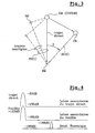
- the processing of the received signals comprising a Doppler-distance correlation, the ambiguity function of the COFDM signals and in particular its side lobes must be studied.
- the sidelobes of the ambiguity function associated with the COFDM waveform are relatively uniform in the distance-Doppler plane, and their level relative to the main lobe is -10.log 10 (IK).
- the secondary lobes are lower at the foot of the main peak.
- the link budget between the EM transmitter and the RE receiver is shown in FIG. figure 4 .
- the energy contained in the side lobes attached to the direct path and to clutter (clutter) due to multiple paths is preponderant compared to the thermal noise.
- a passive radar receiver REa for OFDM signals comprises a received signal shaping circuit 1, a correlated signal filtering circuit 2, a correlated signal detector 3, a target determination circuit 4 and a signal detection circuit 4. transmitter signal replication estimator 5.
- the circuit 13 estimates the parameters of the transmitted signal, such as the carrier frequency F 0 and the symbol duration T S as a function of an analysis of the first two symbols S 1 and S 2 of a frame ( figure 2 ) in order to constitute a temporal reference. Knowing the period T S ' of the transmitted signal and the duration duration T S of each symbol, the temporal length of the channel is deduced from the synchronization process of the previous time reference, by analyzing the signal received within each guard interval ⁇ which is greater than the channel time length.
- the received signal is truncated periodically in a truncation circuit 14.
- the stationary part of the received symbols of duration T S is recovered by removing the received signal portion in the guard interval ⁇ of each period T S ' and particularly by removing the deduced channel length in each period.
- Each portion of duration T S in the received digital baseband signal is then applied to a Fourier analyzer 21 at the input of the filter circuit 2.
- the analyzer produces the real and imaginary components of the received signal for each duration T S by Hilbert transform and FFT fast Fourier transform analysis to provide the frequency spectrum of each symbol S i delivered by the truncation circuit 14.
- the spectral K lines SP 1 to SP K of the symbol relating to the frequencies f 1 to f K are applied to the detector 3 and to the first inputs of a subtractor 22.
- the information carried by each spectral line SP k relating to a frequency transmitted independently of the other frequencies is linked firstly to the coding of the corresponding spectral line and secondly to the transfer function H k of the propagation channel.
- H k is the average of the I-1 coefficients of the propagation channel transfer function for the line SP k during the symbols S 2 to S I of the frame, that is to say almost
- the noise signal b (t) denotes an average of jammers received during the frame, essentially composed of a thermal noise with a variance lower than that of the jammers B (t).
- the detector 3 After memorizing the transfer function coefficients H 1 to H K averaged over one frame, the detector 3 applies the spectral lines of the correlated signals with zero Doppler effect averaged on a frame, i.e., the averaged lines of the signal SR (t) depending on the coefficients H 1 to H K to K second inputs of the subtractor 22.
- the subtractor subtracts the lines of the signal SR (t) from the received signal spectral lines SP 1 to SP K , relative to each symbol S 2 to S I of the frame.
- the lines of the signal X '(t) are synthesized by inverse fast Fourier transform FFT -1 in a synthesizer 23 which restores the symbol train of the digital signal X' (t) mainly comprising the signal of SC target backscattering (t).
- This signal X '(t) is applied to the target discrimination circuit 4.
- the target discrimination circuit 4 comprises a Doppler-distance correlator 41.
- Doppler channels in the correlator 41 are assigned a predetermined frequency deviation from each other due to the Doppler effect.
- the Doppler channels constitute several boxes of the speed of the filtered signal X '(t) by frequency changes and are each correlated, for each carrier f 1 to f K , to the replica of the transmitted signal Re ( ⁇ ).
- an angular focusing circuit 42 determines angular boxes positioning moving targets.
- TFAC Constant False Alarm Processing circuit
- this first embodiment has been described for a bistatic radar, it can be applied to a monostatic radar. It can also be implemented in a radar with several reception antennas and therefore several filtering by spectral line subtraction depending on the transfer function coefficients.
- H 1 to H K for the K spectral lines relating to each receiving antenna in the filter circuit 2 which produces as many filtered signals X '(t) as antennas to be processed in parallel in Doppler channels of the circuit 4, as in the circuit 4b shown in the figure 6 .
- the received signal X (t) was processed to eliminate the contribution of the direct path and multiple paths between at least one COFDM emitter EM and the receiver REa.
- the interferers such as interference signals and thermal noise in the useful frequency band, were not eliminated in the signal X '(t) processed by the correlator 41.
- the REb Radar receiver aims to eliminate all interfering signals interfering and interfering.
- the receiver REb comprises several receiving antennas 11 1 to 11 N respectively connected to several receivers 12 1 to 12 N for COFDM signals with N ⁇ 2.
- the radar receiver REb has a structure similar to that REa shown in FIG. figure 5 , but with N parallel reception channels between the circuits 13b, 14b, 2b and 4b respectively associated with the antennas 11 1 to 11 N.
- the detector 3 and the replica estimator 5 are not modified.
- the detector 3 produces a reference signal SR (t) relative to one of the antennas 11 1 to 11 N , for example as a function of the K spectral lines SP 11 to SP K1 of the first channel connected to the antenna 11 1 , which are delivered by the spectrum analyzer 21b which analyzes N received symbol trains provided by the truncation circuit 14b.
- the estimator 5 produces a replica of the narrowband transmitted signal Re (t) applied to N Doppler-distance correlators 41b in the target discrimination circuit 4.
- the REb receiver Compared to the REa receiver, the REb receiver essentially differs from it by the narrow-band filtering circuit 2b which suppresses the zero Doppler spurious signals TD (t) and the scramblers B (t).
- the filter circuit 2b comprises, between the spectrum analyzer 21b producing in parallel K spectral lines for each symbol of the received signals X 1 (t) to X N (t) and the Fourier synthesizer 23b providing N filtered signals.
- the module 24b estimates a covariance matrix R k of dimensions NxN in which a line of given rank n is composed of the products of the spectral line SP kn received relative to a given antenna 11 n by the conjugates of received spectral lines SP k1 to SP kN received relative to the N antennas 11 1 to 11 N , the products being averaged for symbols for a predetermined duration, with 1 ⁇ n ⁇ N.
- the predetermined duration for averaging said products is significantly longer than the symbol duration T S , and is typically the duration of one frame, ie products averaged over I-1 symbols S 2 to S I.
- the orthogonality of the spectral lines between them makes it possible to make the covariance matrices R 1 to R K independent of the coding.
- the module 25b deduces the inverse matrices R 1 - 1 at R K - 1 K matrices of covariance and memorizes them.
- K inverse matrices of dimensions NxN act as K filters in the module 26b respectively to filter K groups of N spectral lines each SP 11 - SP 1N to SP K1 - SP KN delivered by the analyzer 21b.
- Each group of N received spectral lines SP k1 to SP kN for a given frequency f k is thus filtered by a filter which at each symbol provides the product of the column vector composed of the N received spectral lines SP k1 - SP kN for this symbol and the frequency f k by the inverse matrix R k - 1 .
- the N groups with K filtering signals each supplied by the filtering module 26b are then applied to the synthesizer 23b which delivers N symbol time signals.
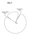
- X 1 ' t at X NOT ' t in the correlators 41b are followed by angular focusing circuits 42b and a TFAC circuit 43b.
- the signal radiation pattern X 1 ' t at X NOT ' t has blind axes, ie "holes" according to the directions of reception of the OFDM correlated signals and jammers, as shown in FIG. figure 7 .
Landscapes
- Engineering & Computer Science (AREA)
- Radar, Positioning & Navigation (AREA)
- Remote Sensing (AREA)
- Computer Networks & Wireless Communication (AREA)
- Physics & Mathematics (AREA)
- General Physics & Mathematics (AREA)
- Radar Systems Or Details Thereof (AREA)
Claims (6)
- Radarempfänger zum Verarbeiten eines Funksignals, das über einen Ausbreitungskanal (EM-RE) empfangen wird, und sich aus Symbolrastern zusammensetzt, die jeweils auf codierten orthogonalen Trägern (f1-fk) ausgesandt werden, umfassend eine Empfangsvorrichtung (11, 12), um das empfangene Signal in die Form eines digitalen Symbolsignals zu bringen und eine Doppler-Entfernung (4) Korrelationsvorrichtung zum Unterscheiden der beweglichen Ziele, dadurch gekennzeichnet, dass er eine Vorrichtung (13) zum Einschätzen der Parameter des ausgesandten digitalen Signals (X, S1-SI) in zwei Symbolen (S1, S2) des Rasters umfasst, eine Vorrichtung (21), die die besagten Parameter verwendet, um Spektrallinien (SP1 - SPk) aus dem digitalen Symbolsignal (X) entsprechend den orthogonalen Trägern (f1-fk) herzustellen, und eine Vorrichtung zur Frequenzfilterung (2) unter Verwendung der besagten Parameter zum Eliminieren zumindest der Parasitensignale mit Null Dopplereffekt (TD) aus den Spektrallinien (SP1 - SPk), um ein gefiltertes digitales Signal (X') anzuwenden, das im Wesentlichen Signale (SC) umfasst, die von den Zielen (CB) über die Korrelationsvorrichtung (4) zurückgestrahlt werden,
wobei die Vorrichtung zur Frequenzfilterung (2) eine Vorrichtung (3) zum Erfassen von Parasitensignalen mit Null Dopplereffekt (TD) durch die Einschätzung von Koeffizienten der Transferfunktion (H1 - Hk) des Ausbreitungskanals jeweils in den Spektrallinien umfasst, sowie eine Vorrichtung (22) zum Subtrahieren der Spektrallinien der Parasitensignale mit Null Dopplereffekt (TD), die von den Koeffizienten der eingeschätzten Transferfunktion abgeleitet werden, von den Spektrallinien des Symbolsignals (SP1 - SPk), und eine Vorrichtung (23) zum synthetischen Erzeugen der Spektrallinien, die von der Vorrichtung (22) zum Subtrahieren im gefilterten digitalen Signal (X') erzeugt werden. - Radarempfänger nach Anspruch 1, bei dem die Spektrallinien der Parasitensignale (TD) für jedes Symbol eingeschätzt werden, und auf jedem Raster in der Erfassungsvorrichtung (3) gemittelt werden, bevor sie von den Spektrallinien (SP1 - SPk) des digitalen Symbolsignals subtrahiert werden.
- Radarempfänger nach Anspruch 1 oder 2, umfassend eine Vorrichtung (5) zum Einschätzen einer Replik eines ausgesandten Signals (Re) in Abhängigkeit von den Spektrallinien der Parasitensignale mit Null Dopplereffekt (TD), wobei die eingeschätzte Replik in der Doppler-Entfernung (4) Korrelationsvorrichtung mit dem gefilterten Signal (X') korreliert wird.
- Radarempfänger zum Verarbeiten eines Funksignals, das über einen Ausbreitungskanal (EM-RE) empfangen wird, und sich aus Symbolrastern zusammensetzt, die jeweils auf codierten orthogonalen Trägern (f1-fk) ausgesandt werden, umfassend mehrere Empfangsvorrichtungen (111, 121 bis 11N, 12N), um mehrere empfangene Signale in die Form von digitalen Symbolsignalen (X1 - XN) zu bringen und eine Doppler-Distanz (4b) Korrelationsvorrichtung zum Unterscheiden der beweglichen Ziele, dadurch gekennzeichnet, dass er eine Vorrichtung (13b) zum Einschätzen der Parameter des ausgesandten digitalen Signals (X, S1-SI) in zwei Symbolen (S1, S2) des Rasters umfasst, eine Vorrichtung (21 b), die die besagten Parameter verwendet, um Spektrallinien (SP11 - SP1N bis SPK1 - SPKN) aus den digitalen Symbolsignalen (X1 - XN) jeweils entsprechend den orthogonalen Trägern (f1-fk) herzustellen, und eine Vorrichtung zur Frequenzfilterung (2) unter Verwendung der besagten Parameter zum Eliminieren zumindest der Parasitensignale mit Null Dopplereffekt (TD) aus den Spektrallinien (SP11 - SP1N bis SPK1 - SPKN), um gefilterte digitale Signale (X'1 - X'N) anzuwenden, die im Wesentlichen Signale (SC) umfassen, die von den Zielen (CB) Korrelationsvorrichtungen (4b) zurückgestrahlt werden,
wobei die Vorrichtung zur Frequenzfilterung (2b) eine Vorrichtung (24b) zum Einschätzen von Kovarianz-Matrizen (R1-RK) umfasst, die jeweils paarweise in einer Gruppe in Bezug auf einen jeweiligen Träger (fK) von Produkten der Spektrallinien (SPk1 - SPkN) abhängen, eine Vorrichtung (25b) zum Ableiten der Umkehrmatrizen (R-1 1-R-1 k) der Kovarianz-Matrizen, eine Vorrichtung (26b) zum Filtern der Spektralliniengruppen jeweils in Bezug auf die Träger (f1-fk) durch das Multiplizieren der Liniengruppen mit den jeweiligen Umkehrmatrizen zum Erzeugen von gefilterten Spektralliniengruppen und eine Vorrichtung (23b) zum synthetischen Erzeugen der gefilterten Spektralliniengruppen in gefilterten digitalen Symbolsignalen (X'1-X'N), die im Wesentlichen Signale (SC) umfassen, die von den Zielen (CB) über die Korrelationsvorrichtung (4b) zurückgestrahlt werden. - Radarempfänger nach Anspruch 4, bei dem die Spektrallinienprodukte, von denen die Kovarianz-Matrizen (R1-RK) abhängen, von Symbolspektrallinien abhängen und auf jeder Matrize gemittelt werden.
- Radarempfänger nach Anspruch 4 oder 5, umfassend eine Vorrichtung (3, 5) zum Einschätzen einer Replik eines ausgesandten Signals (Re) in Abhängigkeit von den Spektrallinien (SP11 - SPk1) eines der Symbolsignale (X1) durch die Einschätzung von Koeffizienten der Transferfunktion des Ausbreitungskanals in den Parasitensignalen mit Null Dopplereffekt, wobei die eingeschätzte Replik in der Korrelationsvorrichtung (4b) mit den gefilterten digitalen Symbolsignalen (X'1-X'N) korreliert wird.
Applications Claiming Priority (3)
| Application Number | Priority Date | Filing Date | Title |
|---|---|---|---|
| FR0101695A FR2820507B1 (fr) | 2001-02-07 | 2001-02-07 | Rejection de fouillis dans un recepteur radar passif de signaux ofdm |
| FR0101695 | 2001-02-07 | ||
| PCT/FR2002/000224 WO2002063335A1 (fr) | 2001-02-07 | 2002-01-18 | Rejection de fouillis dans un recepteur radar passif de signaux ofdm |
Publications (2)
| Publication Number | Publication Date |
|---|---|
| EP1358505A1 EP1358505A1 (de) | 2003-11-05 |
| EP1358505B1 true EP1358505B1 (de) | 2012-05-30 |
Family
ID=8859762
Family Applications (1)
| Application Number | Title | Priority Date | Filing Date |
|---|---|---|---|
| EP02708403A Expired - Lifetime EP1358505B1 (de) | 2001-02-07 | 2002-01-18 | Störechounterdrückung in einem passiven radarempfänger für ofdm signale |
Country Status (6)
| Country | Link |
|---|---|
| US (1) | US6924763B2 (de) |
| EP (1) | EP1358505B1 (de) |
| JP (1) | JP3918735B2 (de) |
| ES (1) | ES2387264T3 (de) |
| FR (1) | FR2820507B1 (de) |
| WO (1) | WO2002063335A1 (de) |
Families Citing this family (37)
| Publication number | Priority date | Publication date | Assignee | Title |
|---|---|---|---|---|
| US7952511B1 (en) | 1999-04-07 | 2011-05-31 | Geer James L | Method and apparatus for the detection of objects using electromagnetic wave attenuation patterns |
| FR2834072B1 (fr) | 2001-12-26 | 2006-08-04 | Onera (Off Nat Aerospatiale) | Rejection de fouillis dans un recepteur radar passif de sign aux ofdm a reseau d'antennes |
| ATE483172T1 (de) * | 2003-05-21 | 2010-10-15 | Ericsson Telefon Ab L M | Verfahren und system zur unzweideutigen winkelauflösung einer spärlichen breitbandantennengruppe |
| JP4555656B2 (ja) * | 2003-10-16 | 2010-10-06 | 日本放送協会 | 電波到来方向推定装置 |
| US7852259B2 (en) | 2004-01-23 | 2010-12-14 | Telefonaktiebolaget Lm Ericsson (Publ) | Clutter filtering |
| US7864884B2 (en) * | 2006-04-27 | 2011-01-04 | Nokia Corporation | Signal detection in OFDM system |
| US8045927B2 (en) * | 2006-04-27 | 2011-10-25 | Nokia Corporation | Signal detection in multicarrier communication system |
| US8212717B2 (en) * | 2006-10-26 | 2012-07-03 | Raytheon Company | Radar imaging system and method using second moment spatial variance |
| US8054217B2 (en) * | 2006-10-26 | 2011-11-08 | Raytheon Company | Radar imaging system and method using gradient magnitude second moment spatial variance detection |
| FR2915288B1 (fr) * | 2007-04-17 | 2009-06-05 | Thales Sa | Procede de depollution de signaux pour un antibrouillage centralise. |
| US7646332B2 (en) * | 2007-08-09 | 2010-01-12 | Raytheon Company | Method and apparatus for interleaved gridding in distributed multiple computing for real-time RCS prediction |
| US7652620B2 (en) * | 2007-08-09 | 2010-01-26 | Raytheon Company | RCS signature generation for closely spaced multiple objects using N-point models |
| DE602008002813D1 (de) * | 2008-02-22 | 2010-11-11 | Thales Nederland Bv | Verfahren zur Messung der Radialgeschwindigkeit eines Ziels mit einem Doppler-Radar |
| TWI475847B (zh) * | 2008-04-16 | 2015-03-01 | Koninkl Philips Electronics Nv | 存在及移動偵測之被動雷達 |
| DE602008002824D1 (de) * | 2008-05-23 | 2010-11-11 | Thales Nederland Bv | Verfahren zur Schätzung der Position und der Geschwindigkeit eines Ziels mit einem Radar, der eine OFDM-Welle aussendet |
| US7602332B1 (en) | 2008-06-13 | 2009-10-13 | Raytheon Company | Reducing scattering center data using multi-volume aggregation |
| US7616151B1 (en) * | 2008-06-13 | 2009-11-10 | Raytheon Company | Reducing scattering center data using magnitude-based reduction |
| US7750842B2 (en) * | 2008-09-18 | 2010-07-06 | Raytheon Company | Parallel processing to generate radar signatures for multiple objects |
| US7592947B1 (en) | 2008-09-18 | 2009-09-22 | Raytheon Company | Generating radar signatures for multiple objects |
| US7880671B2 (en) * | 2008-09-18 | 2011-02-01 | Raytheon Company | Electromagnetic (EM) solver using a shooting bouncing ray (SBR) technique |
| KR100971773B1 (ko) * | 2009-11-13 | 2010-07-21 | 엘아이지넥스원 주식회사 | 전자 정보 수신기의 신호 식별 방법 |
| US8390508B1 (en) | 2010-04-05 | 2013-03-05 | Raytheon Company | Generating radar cross-section signatures |
| CN102621538B (zh) * | 2012-04-20 | 2013-10-16 | 西安电子科技大学 | 雷达信号处理机中的截位电路及其截位方法 |
| FR3034274B1 (fr) | 2015-03-27 | 2017-03-24 | Stmicroelectronics Rousset | Procede de traitement d'un signal analogique issu d'un canal de transmission, en particulier un signal vehicule par courant porteur en ligne |
| FR3038800A1 (fr) | 2015-07-09 | 2017-01-13 | Stmicroelectronics Rousset | Procede de traitement d'un signal issu d'un canal de transmission, en particulier un signal vehicule par courant porteur en ligne, et notamment l'estimation du canal, et recepteur correspondant |
| US9838077B2 (en) | 2015-07-09 | 2017-12-05 | Stmicroelectronics (Rousset) Sas | Method for estimating a cyclostationary transmission channel, and corresponding receiver |
| FR3038801B1 (fr) | 2015-07-09 | 2017-07-21 | Stmicroelectronics Rousset | Procede d'estimation d'un canal de transmission temporellement invariant, et recepteur correspondant |
| CN105785331B (zh) * | 2016-03-02 | 2018-05-29 | 河海大学 | 一种采用盲源分离的外辐射源雷达直达波恢复方法 |
| CN106291502B (zh) * | 2016-08-30 | 2018-11-09 | 北京航空航天大学 | 目标rcs测量中背景提取与抵消的最大概率时域处理方法 |
| SG11201909685RA (en) | 2017-05-12 | 2019-11-28 | Locata Corp | Methods and apparatus for characterising the environment of a user platform |
| FI131680B1 (en) * | 2018-02-14 | 2025-09-10 | Teknologian Tutkimuskeskus Vtt Oy | Radar |
| CN108549048B (zh) * | 2018-03-23 | 2021-10-22 | 武汉大学 | 一种多频WiFi外辐射源雷达相参处理方法 |
| JP6587199B1 (ja) * | 2018-07-03 | 2019-10-09 | パナソニックIpマネジメント株式会社 | 推定装置および推定方法 |
| CN111077515B (zh) * | 2019-12-20 | 2023-02-10 | 西安电子科技大学 | 一种基于模拟电视外辐射源雷达的目标检测方法 |
| CN114660553B (zh) * | 2022-03-28 | 2025-09-26 | 北京理工大学 | 基于原子范数的外辐射源雷达多径杂波的时延估计方法 |
| CN114859313B (zh) * | 2022-04-28 | 2023-04-28 | 长沙祥云瑞风信息技术有限公司 | 一种基于基带跳频实现的距离解模糊方法、系统及设备 |
| CN116755044A (zh) * | 2023-05-06 | 2023-09-15 | 北京理工大学 | 一种外辐射源雷达频域滑动扩展对消方法 |
Family Cites Families (10)
| Publication number | Priority date | Publication date | Assignee | Title |
|---|---|---|---|---|
| US3972041A (en) * | 1971-03-17 | 1976-07-27 | International Telephone And Telegraph Corporation | Adaptive clutter velocity cancellation system for pulsed digital MTI system |
| US3831174A (en) * | 1973-02-05 | 1974-08-20 | Hughes Aircraft Co | Automatic target acquisition in mti radar system |
| US3987442A (en) * | 1974-06-24 | 1976-10-19 | Raytheon Company | Digital MTI radar system |
| US4137533A (en) * | 1977-10-12 | 1979-01-30 | United Technologies Corporation | Angle/vector processed, phase-accumulated single vector rotation, variable order adaptive MTI processor |
| JPS60379A (ja) * | 1983-06-16 | 1985-01-05 | Mitsubishi Electric Corp | 移動目標指示レ−ダ装置 |
| US4618864A (en) * | 1984-01-31 | 1986-10-21 | Westinghouse Electric Corp. | Radar channel including an orthogonal MTI filter pair |
| FR2719382B1 (fr) * | 1994-05-02 | 1996-05-31 | Thomson Csf | Procédé de détection radar discrète et système de mise en Óoeuvre. |
| FR2776438B1 (fr) * | 1996-04-30 | 2000-05-05 | Dassault Electronique | Systeme de detection de mobiles, utilisant les emissions de telediffusion numerique d'un reseau d'emetteurs terrestres |
| US5973642A (en) * | 1998-04-01 | 1999-10-26 | At&T Corp. | Adaptive antenna arrays for orthogonal frequency division multiplexing systems with co-channel interference |
| US6400306B1 (en) * | 1999-12-17 | 2002-06-04 | Sicom Systems, Ltd | Multi-channel moving target radar detection and imaging apparatus and method |
-
2001
- 2001-02-07 FR FR0101695A patent/FR2820507B1/fr not_active Expired - Fee Related
-
2002
- 2002-01-18 WO PCT/FR2002/000224 patent/WO2002063335A1/fr not_active Ceased
- 2002-01-18 EP EP02708403A patent/EP1358505B1/de not_active Expired - Lifetime
- 2002-01-18 JP JP2002563026A patent/JP3918735B2/ja not_active Expired - Fee Related
- 2002-01-18 US US10/470,713 patent/US6924763B2/en not_active Expired - Fee Related
- 2002-01-18 ES ES02708403T patent/ES2387264T3/es not_active Expired - Lifetime
Also Published As
| Publication number | Publication date |
|---|---|
| US6924763B2 (en) | 2005-08-02 |
| JP2004531701A (ja) | 2004-10-14 |
| FR2820507A1 (fr) | 2002-08-09 |
| US20040066331A1 (en) | 2004-04-08 |
| JP3918735B2 (ja) | 2007-05-23 |
| FR2820507B1 (fr) | 2003-03-28 |
| WO2002063335A1 (fr) | 2002-08-15 |
| ES2387264T3 (es) | 2012-09-19 |
| EP1358505A1 (de) | 2003-11-05 |
Similar Documents
| Publication | Publication Date | Title |
|---|---|---|
| EP1358505B1 (de) | Störechounterdrückung in einem passiven radarempfänger für ofdm signale | |
| EP1476768B1 (de) | Störechobeseitigung in einem passiven radarempfänger für ofdm signale mit einem antennennetzwerk | |
| EP0441730B1 (de) | Verfahren zur Datenverbreitung mit Zeit-Frequenzverschachtelung mit Verwendung von Bezugsfrequenzsignalen | |
| EP1214608B1 (de) | Anordnung zur erkennung von mobilen die die sendungen eines digitalen rundfunks eines netzes irdischen senders verwendet | |
| EP0441731A1 (de) | Verfahren zur Datenverbreitung mit Zeit-Frequenzverschachtelung und kohärenter Demodulation | |
| EA002611B1 (ru) | Структура кадра и синхронизация частоты для систем с множеством несущих | |
| EP1260071B1 (de) | Verfahren und vorrichtung für kanalschäztung | |
| EP3232626A1 (de) | Sender für fbmc-system mit raum-zeit-blockkodierverfahren vom typ alamouti | |
| EP1446927B1 (de) | Schätzen eines übertragungskanals mit in einer verbandstruktur verteilten pilotsymbolen | |
| FR2877786A1 (fr) | Procede de reception d'un signal multiporteuse mettant en oeuvre au moins deux estimations d'un canal de propagation et dispositif de reception correspondant | |
| EP1972068B1 (de) | Verfahren zur symboldetektion sowie entsprechender empfänger | |
| FR2790344A1 (fr) | Demodulateur cofdm avec compensation de deplacement de fenetre d'analyse fft | |
| FR3011425A1 (fr) | Procede de determination des imperfections d'une voie d'emission et d'une voie de reception d'un equipement, equipement et poste radio associe | |
| EP4105673B1 (de) | Methode zur einschätzung der eigenschaften eines gepulsten ultrabreitbandsignals, das von mehreren antennen ausgesendet wird | |
| CN114397649B (zh) | 一种基于子载波的目标匹配方法 | |
| Weiler et al. | The effect of cosine phased BOC modulation on the GNSS receiver search process | |
| EP2201735B1 (de) | Synchronisierung von datenübertragungsrahmen in einem ofdm-kommunikationssystem | |
| EP2517038B1 (de) | Verfahren und vorrichtung zur goniometrie von mit einem von mehreren trägern modulierten nützlichen signal interferierenden signalen | |
| EP0574282B1 (de) | Einrichtung zur Kodierung und Dekodierung zur Übertragung in Frequenzteilbändern | |
| WO1998059475A1 (fr) | Procede et dispositif de correction frequentielle en modulation a frequence porteuse variable et plusieurs sous-porteuses |
Legal Events
| Date | Code | Title | Description |
|---|---|---|---|
| PUAI | Public reference made under article 153(3) epc to a published international application that has entered the european phase |
Free format text: ORIGINAL CODE: 0009012 |
|
| 17P | Request for examination filed |
Effective date: 20030719 |
|
| AK | Designated contracting states |
Kind code of ref document: A1 Designated state(s): AT BE CH CY DE DK ES FI FR GB GR IE IT LI LU MC NL PT SE TR |
|
| AX | Request for extension of the european patent |
Extension state: AL LT LV MK RO SI |
|
| RIN1 | Information on inventor provided before grant (corrected) |
Inventor name: POULLIN, DOMINIQUE |
|
| 17Q | First examination report despatched |
Effective date: 20090331 |
|
| GRAP | Despatch of communication of intention to grant a patent |
Free format text: ORIGINAL CODE: EPIDOSNIGR1 |
|
| GRAC | Information related to communication of intention to grant a patent modified |
Free format text: ORIGINAL CODE: EPIDOSCIGR1 |
|
| GRAS | Grant fee paid |
Free format text: ORIGINAL CODE: EPIDOSNIGR3 |
|
| GRAA | (expected) grant |
Free format text: ORIGINAL CODE: 0009210 |
|
| AK | Designated contracting states |
Kind code of ref document: B1 Designated state(s): AT BE CH CY DE DK ES FI FR GB GR IE IT LI LU MC NL PT SE TR |
|
| REG | Reference to a national code |
Ref country code: GB Ref legal event code: FG4D Free format text: NOT ENGLISH |
|
| REG | Reference to a national code |
Ref country code: CH Ref legal event code: EP |
|
| REG | Reference to a national code |
Ref country code: AT Ref legal event code: REF Ref document number: 560304 Country of ref document: AT Kind code of ref document: T Effective date: 20120615 |
|
| REG | Reference to a national code |
Ref country code: IE Ref legal event code: FG4D Free format text: LANGUAGE OF EP DOCUMENT: FRENCH |
|
| REG | Reference to a national code |
Ref country code: DE Ref legal event code: R096 Ref document number: 60243029 Country of ref document: DE Effective date: 20120802 |
|
| REG | Reference to a national code |
Ref country code: NL Ref legal event code: VDEP Effective date: 20120530 Ref country code: ES Ref legal event code: FG2A Ref document number: 2387264 Country of ref document: ES Kind code of ref document: T3 Effective date: 20120919 |
|
| PG25 | Lapsed in a contracting state [announced via postgrant information from national office to epo] |
Ref country code: FI Free format text: LAPSE BECAUSE OF FAILURE TO SUBMIT A TRANSLATION OF THE DESCRIPTION OR TO PAY THE FEE WITHIN THE PRESCRIBED TIME-LIMIT Effective date: 20120530 Ref country code: CY Free format text: LAPSE BECAUSE OF FAILURE TO SUBMIT A TRANSLATION OF THE DESCRIPTION OR TO PAY THE FEE WITHIN THE PRESCRIBED TIME-LIMIT Effective date: 20120530 Ref country code: SE Free format text: LAPSE BECAUSE OF FAILURE TO SUBMIT A TRANSLATION OF THE DESCRIPTION OR TO PAY THE FEE WITHIN THE PRESCRIBED TIME-LIMIT Effective date: 20120530 |
|
| REG | Reference to a national code |
Ref country code: AT Ref legal event code: MK05 Ref document number: 560304 Country of ref document: AT Kind code of ref document: T Effective date: 20120530 |
|
| PG25 | Lapsed in a contracting state [announced via postgrant information from national office to epo] |
Ref country code: GR Free format text: LAPSE BECAUSE OF FAILURE TO SUBMIT A TRANSLATION OF THE DESCRIPTION OR TO PAY THE FEE WITHIN THE PRESCRIBED TIME-LIMIT Effective date: 20120831 |
|
| PG25 | Lapsed in a contracting state [announced via postgrant information from national office to epo] |
Ref country code: NL Free format text: LAPSE BECAUSE OF FAILURE TO SUBMIT A TRANSLATION OF THE DESCRIPTION OR TO PAY THE FEE WITHIN THE PRESCRIBED TIME-LIMIT Effective date: 20120530 Ref country code: AT Free format text: LAPSE BECAUSE OF FAILURE TO SUBMIT A TRANSLATION OF THE DESCRIPTION OR TO PAY THE FEE WITHIN THE PRESCRIBED TIME-LIMIT Effective date: 20120530 Ref country code: DK Free format text: LAPSE BECAUSE OF FAILURE TO SUBMIT A TRANSLATION OF THE DESCRIPTION OR TO PAY THE FEE WITHIN THE PRESCRIBED TIME-LIMIT Effective date: 20120530 |
|
| PG25 | Lapsed in a contracting state [announced via postgrant information from national office to epo] |
Ref country code: PT Free format text: LAPSE BECAUSE OF FAILURE TO SUBMIT A TRANSLATION OF THE DESCRIPTION OR TO PAY THE FEE WITHIN THE PRESCRIBED TIME-LIMIT Effective date: 20121001 |
|
| PLBE | No opposition filed within time limit |
Free format text: ORIGINAL CODE: 0009261 |
|
| STAA | Information on the status of an ep patent application or granted ep patent |
Free format text: STATUS: NO OPPOSITION FILED WITHIN TIME LIMIT |
|
| 26N | No opposition filed |
Effective date: 20130301 |
|
| REG | Reference to a national code |
Ref country code: DE Ref legal event code: R097 Ref document number: 60243029 Country of ref document: DE Effective date: 20130301 |
|
| BERE | Be: lapsed |
Owner name: ONERA (OFFICE NATIONAL D'ETUDES ET DE RECHERCHES Effective date: 20130131 |
|
| PG25 | Lapsed in a contracting state [announced via postgrant information from national office to epo] |
Ref country code: MC Free format text: LAPSE BECAUSE OF NON-PAYMENT OF DUE FEES Effective date: 20130131 |
|
| REG | Reference to a national code |
Ref country code: CH Ref legal event code: PL |
|
| REG | Reference to a national code |
Ref country code: IE Ref legal event code: MM4A |
|
| PG25 | Lapsed in a contracting state [announced via postgrant information from national office to epo] |
Ref country code: LI Free format text: LAPSE BECAUSE OF NON-PAYMENT OF DUE FEES Effective date: 20130131 Ref country code: CH Free format text: LAPSE BECAUSE OF NON-PAYMENT OF DUE FEES Effective date: 20130131 Ref country code: BE Free format text: LAPSE BECAUSE OF NON-PAYMENT OF DUE FEES Effective date: 20130131 |
|
| PG25 | Lapsed in a contracting state [announced via postgrant information from national office to epo] |
Ref country code: IE Free format text: LAPSE BECAUSE OF NON-PAYMENT OF DUE FEES Effective date: 20130118 |
|
| PG25 | Lapsed in a contracting state [announced via postgrant information from national office to epo] |
Ref country code: TR Free format text: LAPSE BECAUSE OF FAILURE TO SUBMIT A TRANSLATION OF THE DESCRIPTION OR TO PAY THE FEE WITHIN THE PRESCRIBED TIME-LIMIT Effective date: 20120530 |
|
| PG25 | Lapsed in a contracting state [announced via postgrant information from national office to epo] |
Ref country code: LU Free format text: LAPSE BECAUSE OF NON-PAYMENT OF DUE FEES Effective date: 20130118 |
|
| REG | Reference to a national code |
Ref country code: FR Ref legal event code: PLFP Year of fee payment: 15 |
|
| PGFP | Annual fee paid to national office [announced via postgrant information from national office to epo] |
Ref country code: GB Payment date: 20151224 Year of fee payment: 15 |
|
| PGFP | Annual fee paid to national office [announced via postgrant information from national office to epo] |
Ref country code: FR Payment date: 20151222 Year of fee payment: 15 |
|
| PGFP | Annual fee paid to national office [announced via postgrant information from national office to epo] |
Ref country code: IT Payment date: 20160111 Year of fee payment: 15 Ref country code: DE Payment date: 20151217 Year of fee payment: 15 Ref country code: ES Payment date: 20160114 Year of fee payment: 15 |
|
| REG | Reference to a national code |
Ref country code: DE Ref legal event code: R119 Ref document number: 60243029 Country of ref document: DE |
|
| GBPC | Gb: european patent ceased through non-payment of renewal fee |
Effective date: 20170118 |
|
| REG | Reference to a national code |
Ref country code: FR Ref legal event code: ST Effective date: 20170929 |
|
| PG25 | Lapsed in a contracting state [announced via postgrant information from national office to epo] |
Ref country code: FR Free format text: LAPSE BECAUSE OF NON-PAYMENT OF DUE FEES Effective date: 20170131 |
|
| PG25 | Lapsed in a contracting state [announced via postgrant information from national office to epo] |
Ref country code: GB Free format text: LAPSE BECAUSE OF NON-PAYMENT OF DUE FEES Effective date: 20170118 Ref country code: DE Free format text: LAPSE BECAUSE OF NON-PAYMENT OF DUE FEES Effective date: 20170801 |
|
| PG25 | Lapsed in a contracting state [announced via postgrant information from national office to epo] |
Ref country code: IT Free format text: LAPSE BECAUSE OF NON-PAYMENT OF DUE FEES Effective date: 20170118 |
|
| REG | Reference to a national code |
Ref country code: ES Ref legal event code: FD2A Effective date: 20180507 |
|
| PG25 | Lapsed in a contracting state [announced via postgrant information from national office to epo] |
Ref country code: ES Free format text: LAPSE BECAUSE OF NON-PAYMENT OF DUE FEES Effective date: 20170119 |