Technical Field
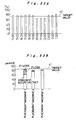
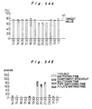
The present invention relates to: a service receiving
device for deriving a service from a production facility
manufacturing supplier, the service being for realizing high-efficiency
and high-quality production of a production line
where a plurality of production facilities including a
component mounting apparatus are connected in order of steps;
a service providing device for providing a service from a
manufacturer side that supplies the production facility; and a
method for providing a service from the production facility
manufacturing supplier. The present invention also relates to
a service receiving program for operating the service
receiving device and a service providing program for operating
the service providing device.
Background Art
A large number of electronic appliances have been reduced
in size as well as in weight, while a circuit board
constituting the electronic appliance has been more and more
highly integrated and mounted at a higher density. On such a
circuit board, components are mounted by the above-mentioned
component mounting apparatus or component mounting line.
This component mounting line is a type of production line
for automatically mounting components on a circuit board. An
example of the production line is constituted by: a board
supplying device for supplying circuit boards in a one-by-one
manner; a cream solder printer for printing a cream solder
onto the circuit board; a cream solder print inspection
machine for inspecting a state of the printed cream solder; an
applicator for applying an adhesive for adhering components
onto the board; a high-speed placement machine for placing the
components onto the circuit board at high speed; a
multifunctional placement machine for placing various kinds of
components including an odd-shaped component onto the circuit
board; a placed component inspection machine for inspecting a
missing component or a positional offset of a component on the
circuit board after placement of the components; a reflow
device for melting the cream solder so as to solder an
electrode of the component and a land on the circuit board to
each other to obtain a mounted state of the components; a
visual inspection machine for visually inspecting a state of
soldering, a placed state of the component or the like; and a
board housing device for housing the mounted circuit board
therein. A plurality of types of these production facilities
are connected in series to each other. Circuit boards
sequentially pass through these devices in a one-by-one manner
so as to achieve the mount production.
Moreover, depending on the kind of electronic component,
equipment in other forms such as a component insertion machine
for inserting a radial lead, an axial lead, or a jumper wire,
a component mounting apparatus for achieving the mounting with
a joint between metals by friction, diffusion due to friction,
or fusion can be used for fabricating a circuit board.
In component mounting apparatus manufacturers supplying a
component mounting apparatus or a component mounting line as
described above, the destination of delivery of a component
mounting apparatus or a component mounting line has been
expanded not only on a domestic scale but also on a global
scale. In this context, a conventional servicing status while
the component mounting apparatus is running upon and after
delivery to the destination of delivery is as follows.
When a component mounting apparatus or a component
mounting line is to be delivered to the destination of
delivery, an operation for installing the component mounting
line and an adjustment operation for setting up the component
mounting line are performed by an operator dispatched from a
component mounting apparatus manufacturer. At this time, an
instructor dispatched from the component mounting apparatus
manufacturer describes the operation of the component mounting
apparatus and offers the training for an operator of the
apparatus at a factory of the destination of delivery, with
reference to an instruction manual delivered along with the
component mounting apparatus.
In a case where the component mounting apparatus is shut
down due to a trouble, or quality defect of products, or the
like occurs during production in the component mounting line
after its delivery, the operator, who has received
instructions for the operation and the training, analyses its
cause at the factory of the destination of delivery so as to
eliminate the trouble or the quality defect. In a case where
the trouble or the quality defect still remains, the component
mounting apparatus manufacturer is requested to dispatch a
service person. The service person is asked to analyze the
cause so as to eliminate the trouble or the quality defect of
products.
Such a service will be specifically described, taking a
component mounting apparatus 450 illustrated in Fig. 67 as an
example. The component mounting apparatus 450 includes: a data
storage section 451 for recording and storing operation
information and error information of the component mounting
apparatus for trouble recovery or maintenance; an output
device 452 (a printer, a floppy disk drive, a display screen,
or the like) for outputting the information stored in the data
storage section 451; and a communication device 454 for
outputting the information to an external personal computer
453 or the like. Moreover, as shown in Fig. 68, a service
point 172 for repairing the trouble occurring in the component
mounting apparatus 450 and performing maintenance for a
customer factory 171 where the apparatus 450 is delivered to
be operated is provided on the manufacturer side.
When a trouble occurs on the customer side, the trouble
is conventionally recovered as in an example of a procedure
shown in a flow chart of Fig. 69. First, in a case where a
trouble occurs in the component mounting apparatus 450 present
in the customer factory 171 (Step S601), an operator on the
customer side outputs the contents of the trouble occurrence,
for example, the operation information and the error
information of the component mounting apparatus and the like,
through the output device 452 of the component mounting
apparatus 450 (Step S602). The output information is
communicated to the service point 172 by using information
transfer means such as a telephone, a facsimile, or the like
(Step S603). Thereafter, a service person who has received the
communication at the service point 172 receives the contents
of the trouble (the operation information, the error
information, and the like of the component mounting apparatus)
so as to check if all data necessary for analysis have been
completed (Step S604). In a case where all data have not been
completed, the service person makes contact with the operator
at the customer factory 171 again so as to collect the
information. In a case where all data have been completed, the
analysis is carried out (Step S605) so that the service person
visits the customer to recover the trouble (Step S606).
The operation of the component mounting apparatus has
been significantly complicated in these days with the
diversification of circuit boards or components to be mounted
and the corresponding sophistication of component mounting
apparatuses. Accordingly, in spite of the service as described
above, shutdown due to a trouble or quality defect of products
is frequently caused by a faulty operation of the operator who
operates a component mounting apparatus.
Moreover, the operators at the destinations of delivery
of component mounting apparatuses have varied levels. From a
global point of view, in particular, the operators at the
destinations of delivery of apparatuses have infinitely varied
levels for the respective zones of the world. Thus, the
quality of component mount production is varied depending on
the level of the operator. As a result, it becomes difficult
to ensure the uniform quality over all factories at the
destinations of delivery.
Particularly, it is difficult for the operator at the
destination of delivery to learn know-how of component
mounting, that is, to select a component mounting condition
depending on the type of a circuit board or a component to be
mounted. Nevertheless, the description of operation or the
training for an operator at the time of delivery of the
apparatus is normally made on the operation for a particular
test circuit board. In many cases, the description or the
training does not cover the learning of selection of a
component mounting condition depending on the type of a
circuit board or a component to be mounted. Thus, it takes
considerable time for an operator at the destination of
delivery to learn such know-how.
For example, an operator for operating the component
mounting apparatus 450 is required to create NC data which is
necessary for the component mounting apparatus to perform an
operation for mounting components. For creation of such data,
it is necessary to search and input a significant amount of
information for an individual component to be mounted, as is
illustrated in Fig. 23. Nonetheless, the utilization of a
system for automatically creating NC data from a component
database has an advantage in that it is no more necessary to
perform any research and input for a component which is once
used and registered in the component database. However, there
may sometimes be a trial and error process during production
to confirm if the input contents are really suitable or not.
Moreover, the number of types of components to be mounted,
used in the component mount industry, is estimated to be
100,000 or more in total. In the field of mounting such
various kinds of components, the number of components to be
newly mounted is hardly reduced in an actual condition. Thus,
the contents are likely to be misinput upon creation of NC
data. An error in the input contents leads to a trouble of a
component mounting apparatus or quality defect of products.
What is worse, as the workload of creating the NC data is
increased to be enormous, there is an increased possibility
that the misinput might occur.
In addition to this, the workload is similarly high in
teaching of component recognition data, setting of a squeegee
operating condition in screen printing of a cream solder,
setting of a heating temperature profile in a reflow device,
and the like, which results in an increased possibility that
the misinput might occur.
In a case where the shutdown of a component mounting
apparatus caused by a trouble or quality defect of products
occurs due to a faulty operation by the operator, the support
is hardly provided in a timely manner under a servicing
condition as conventional. In many cases, it is only after the
analysis of the cause by a service person dispatched from a
component mounting apparatus manufacturer that the cause of
the trouble is proved to be a faulty operation. In some cases,
it is even after several days' stay of the service person at
the mounting field for grasping the phenomenon that the cause
is found. Consequently, it takes several days to recover a
component mounting line, resulting in a considerable amount of
production loss or quality loss.
A main object of the present invention is to provide a
component mounting apparatus, a service providing device, and
a servicing method, in which a component mounting apparatus
side can receive or be provided with a customer service
related to production including the productivity and the
quality maintenance from a manufacturer side supplying the
component mounting apparatus or a service person side through
all communications including the Internet according to the
needs so as to facilitate the implementation of production.
Disclosure of the Invention
In order to achieve the above object, a component
mounting apparatus according to the present invention is an
apparatus for mounting a component on a circuit board, the
apparatus including a communication device which is
connectable to the Internet line and is capable of receiving a
service necessary for mount production through communication
via the Internet line. Furthermore, the communication device:
is used for monitoring an operating status of the component
mounting apparatus by the service person side; notifies the
contents of trouble occurrence to the service person side so
as to allow the reception of a service; is used for a remote
operation during component mounting from the service person
side; is used to collect data for analysis of a trouble,
including production mount data or device operation data
accumulated in the component mounting apparatus, by the
service person side; or allows a software for running the
component mounting apparatus to be installed, or allows a
component library for operating the component mounting
apparatus or other services to be derived from the service
person side. Moreover, the communication device derives a
service from the service information database provided for the
service person side, in which the service information is
accumulated.
A servicing method according to the present invention is
for a component mounting apparatus for mounting a component
onto a circuit board, wherein the component mounting apparatus
is connected to a service person side for providing a service
of the component mounting apparatus via the Internet line, so
that an operating status of the apparatus is monitored by the
service person side via the Internet line.
A service providing device according to the present
invention is for providing a service necessary for mount
production, the device which is provided for a supplier side
or a service person side of a component mounting apparatus
including: a component supplying device for supplying a
component; and component holding means for holding the
component from the component supplying device so as to mount
the component onto a circuit board, or a component mounting
line including the component mounting apparatuses which are
connected to each other, wherein the service providing device
includes: a transmitting/receiving section for
transmitting/receiving information to/from a service receiving
device provided for a user side for effectuating the mount
production using the component mounting apparatus or the
component mounting line, via communication means including the
Internet; and a control section used for derivation of a
service by the service receiving device via the
transmitting/receiving section. Furthermore, the control
section is used for derivation of the service data or a
service software from the service information database by the
service receiving device via the transmitting/receiving
section, or for derivation of a service for analyzing a
problem arising in the component mounting apparatus or a
service for monitoring a production status.
A component mounting apparatus of the present invention
includes a cream solder printer for printing a cream solder on
a circuit board so as to mount a component thereon. The
component mounting apparatus includes: a
transmitting/receiving section for transmitting/receiving
information to a service providing device provided for a
supplier or a service person side of the component mounting
apparatus via communication means including the Internet; an
input section for inputting instructions for deriving a
service; and a control section, in response to the
instructions from the input section, for performing control so
as to derive a service necessary for printing of the cream
solder from the service providing device via the
transmitting/receiving section. Furthermore, the control
section allows the service person side to receive a service
for retrieving information related to characteristics of
various cream solders or a printing condition, or notifies the
service person side of a printing condition or a printing
state or status which is selected to be practically used for
printing of the cream solder by the cream solder printer so
that the service person receives a service, through the
Internet line via the transmitting/receiving section with the
service person side who provides a service of the component
mounting apparatus including the cream solder printer.
A servicing method according to the present invention is
a method for providing a service of a component mounting
apparatus including a cream solder printer for printing a
cream solder onto a circuit board, wherein the servicing
method allows the component mounting apparatus to derive
information related to cream solder printing from a service
person side who provides a service of the component mounting
apparatus via the Internet with the service person side.
A service providing device according to the present
invention is for providing a service necessary for cream
solder printing, which is provided for a provider or a service
person side of a component mounting apparatus including a
cream solder printer for printing a cream solder onto a
circuit board so as to mount a component thereon, wherein the
service providing device includes a service information
database, in which characteristic information of a cream
solder, performance information obtained by accumulating
information related to a printing condition, state or status
which is selected to be practically used by a user side
receiving the service from the service providing device or a
provider or a service person side of a component mounting line,
and/or information which is rendered adequate by using at
least one of monitoring, evaluation, a countermeasure, and
improvement for the accumulated information, is registered as
data to be derived by the service receiving device. In this
case, for a printing condition database for registering the
printing condition of the cream solder among the service
information databases, the control section can intend to
converge the database while accumulating the evaluated
performance of the printing condition as the needs.
The solder characteristic information includes a solder
manufacturer, a product number, a particle size, a viscosity
and other items. When the control section fails to retrieve
the data as a result of retrieval of a product number, the
control section performs the retrieval by a particle size
and/or a viscosity. It is suitable that, in the retrieved
solder characteristic information, characteristic information
close to that of a desired solder product number is treated as
the result.
The printing condition database suitably includes: a new
database containing newly input data; and a basic database to
be retrieved from the service receiving device, to which the
transition is made when the data registered in the new
database is determined to be adequate or stable. It is
suitable that even data related to the same solder product
number, particle size and viscosity are separately accumulated
in the new database, so that the optimal data is selected from
the accumulated data to make the transition to the basic
database.
Other objects and features of the present invention will
be apparent from the following detailed description and the
drawings. The features of the invention can be used alone or
in combinations varied as much as possible.
Brief Description of Drawings
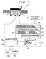
Fig. 1 is a block diagram showing a component mounting
apparatus according to a first embodiment of the present
invention;
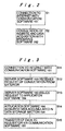
Fig. 2 is a flow chart for connection from the component
mounting apparatus to the Internet in the first embodiment;
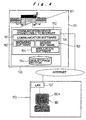
Fig. 3 is a flow chart for connection from the exterior
via the Internet line to the component mounting apparatus in
the first embodiment;
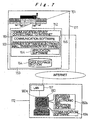
Fig. 4 is a general configuration view showing a customer
servicing method and a device thereof according to a second
embodiment of the present invention;
Fig. 5 is a view showing a specific example of a
monitoring state for the component mounting apparatus through
the Internet line from a remote location in the second
embodiment;
Fig. 6 is a flow chart showing a processing in Fig. 5;
Fig. 7 shows a specific example of a state where trouble
or error information of the component mounting apparatus is
notified to a remote location through the Internet line in the
second embodiment;
Fig. 8 shows a specific example of a state where the
component mounting apparatus is operated from a remote
location through the Internet line in the second embodiment;
Fig. 9 is a flow chart showing a processing in Fig. 8;
Fig. 10 shows a specific example of a state where
production result data and device operation data stored in the
component mounting apparatus are collected from a remote
location through the Internet line in the second embodiment;
Fig. 11 is a flow chart showing a processing in Fig. 10;
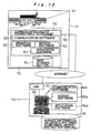
Fig. 12 shows a specific example of a state where a
software in the component mounting apparatus is updated
through the Internet line in the second embodiment;
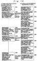
Fig. 13 is a flow chart showing a processing in Fig. 12;
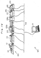
Fig. 14 is a configuration view of a component mounting
system in a third embodiment of the present invention;
Fig. 15 is a general configuration view of a service
system in the third embodiment;
Fig. 16 is a general configuration view of another
service system in the third embodiment;
Figs. 17A and 17B show a configuration of a main part of
a cream solder printer in the third embodiment, where Fig. 17A
is a plan view and Fig. 17B is a front view thereof;
Fig. 18A is a configuration view showing a main part of
one type of placement machine in the third embodiment, and Fig.
18B is a configuration view showing a main part of another
type of placement machine in the third embodiment;
Fig. 19 is a control configuration view of a placement
machine in the third embodiment;
Fig. 20 is a control configuration view of a management
device in the third embodiment;
Fig. 21 is a memory configuration view of a data memory
section of the management device in the third embodiment;
Fig. 22 is a configuration view of facility information
in the third embodiment;
Fig. 23 is a configuration view of NC data in the third
embodiment;
Fig. 24 shows a WEB screen of a service receiving-device
in the third embodiment;
Fig. 25 is a control configuration view of a service
providing device in the third embodiment;
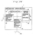
Fig. 26 is a control configuration view of a service
receiving device in the third embodiment;
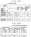
Fig. 27A is a data configuration view of a speed master
in the third embodiment, and Fig. 27B is a data configuration
view of a tact simulation parameter in the third embodiment;
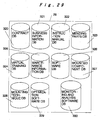
Fig. 28 is a configuration view of an operation quality
information DB in the third embodiment;
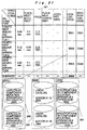
Fig. 29 is a configuration view of a service information
DB in the third embodiment;
Fig. 30 is a configuration view of a contract DB in the
third embodiment;
Fig. 31 is a configuration view of a business information
DB in the third embodiment;
Fig. 32 is a configuration view of an instruction manual
DB in the third embodiment;
Fig. 33 is a configuration view of a a mending part DB in
the third embodiment;
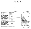
Fig. 34 is a configuration view of a virtual training DB
in the third embodiment;
Fig. 35 is a configuration view of a maintenance
information DB in the third embodiment;
Fig. 36 is a configuration view of a software DB in the
third embodiment;
Fig. 37 is a configuration view of a mounted component DB
in the third embodiment;
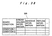
Fig. 38 is a configuration view of a mounting technique
DB in the third embodiment;
Fig. 39 is a configuration view of an optimization
software DB in the third embodiment;
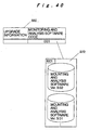
Fig. 40 is a configuration view of a monitoring and
analyzing software DB in the third embodiment;
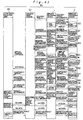
Fig. 41 is a schematic data flow chart of the entire
service system in the third embodiment;
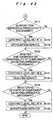
Fig. 42 is the first half of a flow chart showing a
contract and a service in the third embodiment;
Fig. 43 is the second half of the flow chart showing the
contract and the service in the third embodiment;
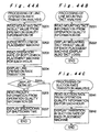
Fig. 44A is a flow chart showing an operation of graph
display for a line operation rate transition analysis
processing related to monitoring and analysis in the third
embodiment, Fig. 44B is a flow chart showing an operation of
graph display for a line mounting tact analysis processing
related to monitoring and analysis in the third embodiment,
and Fig. 44C is a flow chart showing an operation of graph
display for a suction rate transition analysis processing
related to monitoring and analysis in the third embodiment;
Fig. 45 is a flow chart in the case where an operation
rate indicating an operation of monitoring and analysis is a
target value or higher in the third embodiment;
Fig. 46 is a flow chart in the case where the operation
rate is lower than a target value in the third embodiment;
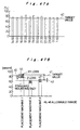
Fig. 47A is a view showing a display screen of line
operation rate transition analysis in the third embodiment,
and Fig. 47B is a view showing a display screen of line tact
analysis corresponding to Fig. 47A;
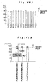
Fig. 48A is a view showing another display screen of line
operation rate transition analysis in the third embodiment,
and Fig. 48B is a view showing a display screen of line tact
analysis corresponding to Fig. 48A;
Fig. 49A is a view showing a further display screen of
line operation rate transition analysis in the third
embodiment, and Fig. 49B is a view showing a display screen of
line mounting tact analysis corresponding to Fig. 49A;
Fig. 50A is a view showing a further display screen of
line operation rate transition analysis in the third
embodiment, and Fig. 50B is a view showing a display screen of
line mounting tact analysis corresponding to Fig. 50A;
Fig. 51A is a view showing a further display screen of
line operation rate transition analysis in the third
embodiment, and Fig. 51B is a view showing a display screen of
shutdown time transition analysis corresponding to Fig. 51A;
Fig. 52A is a view showing a further display screen of
line operation rate transition analysis in the third
embodiment, and Fig. 52B is a view showing a display screen of
component suction rate transition analysis corresponding to
Fig. 52A;
Fig. 53A is a view showing a further display screen of
line operation rate transition analysis in the third
embodiment, and Fig. 53B is a view showing a display screen of
line mounting tact analysis corresponding to Fig. 53A;
Fig. 54A is a view showing a further display screen of
line operation rate transition analysis in the third
embodiment, and Fig. 54B is a view showing a display screen of
shutdown time transition analysis corresponding to Fig. 54A;
Fig. 55A is a view showing a further display screen of
line operation rate transition analysis in the third
embodiment, and Fig. 55B is a view showing a display screen of
shutdown time transition analysis corresponding to Fig. 55A;
Fig. 56 is a flow chart showing an optimization
processing for a placement machine alone in the third
embodiment;
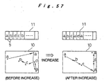
Fig. 57 is an image view showing the relation between the
division of a component supplying device and the component
mounting order in the third embodiment;
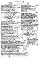
Fig. 58 is a flow chart showing an optimization
processing for revising the optimization processing for the
placement machine alone and the arrangement of common
components in the third embodiment;
Fig. 59A is an image view showing the relation with a
fixed mounting order of the component supplying device in the
third embodiment, and Fig. 59B is an image view showing the
relation when the fixed mounting order shown in Fig. 59A is
replaced by a free mounting order;
Fig. 60A is a view showing an example of simulation of
the arrangement of common components and a production tact in
the third embodiment, and Fig. 60B is a view showing an
example of simulation of type switching time corresponding to
Fig. 60A;
Fig. 61A is a view showing an example of simulation of
the arrangement of partially common components and a
production tact in the third embodiment, and Fig. 61B is a
view showing an example of simulation of type switching time
corresponding to Fig. 61A;
Fig. 62A is a view showing an example of simulation of
the optimal arrangement of individual components and a
production tact in the third embodiment, and Fig. 62B is a
view showing an example of simulation of type switching time
corresponding to Fig. 62A;
Fig. 63 is a flow chart showing a component distribution
correction processing in the third embodiment;
Fig. 64 is a flow chart showing the optimization
processing for the placement machine alone and the component
distribution correction processing in the third embodiment;
Fig. 65 is a flow chart showing the placement machine
unit optimization processing for restraining the vibration of
the component supplying device in the third embodiment;
Fig. 66 is a flow chart showing an expanded optimization
processing of the component supplying device in the third
embodiment;
Fig. 67 is a block diagram showing a conventional
component mounting apparatus;
Fig. 68 is a configuration view of a conventional
customer servicing method and a device thereof;
Fig. 69 is a flow chart showing a conventional procedure
of a trouble recovery method;
Fig. 70 is a configuration view showing an example of a
solder characteristic DB relating to solder characteristics in
cream solder information in the mounting technique DB in the
third embodiment;
Fig. 71 is a configuration view showing an example of a
printing condition DB of a cream solder in the cream solder
information in the mounting technique DB in the third
embodiment;
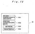
Fig. 72 is a menu screen for handling the cream solder
information on the service receiving device side in the third
embodiment;
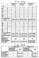
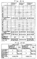
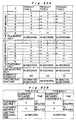
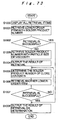
Fig. 73 is a flow chart showing a retrieval operation of
the solder characteristic DB; and
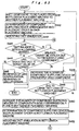
Fig. 74 is a flow chart showing a procedure of creating
the printing condition DB.
Best Mode for Carrying Out the Invention
Hereinafter, some embodiments of the present invention
will be described in detail with reference to the drawings for
understanding of the invention. The embodiments described
below merely show representative specific examples in the case
of a component mounting apparatus for mounting components such
as an electronic component onto a circuit board such as a
printed board so as to fabricate an electronic circuit board,
and therefore do not limit the recitation of the present
invention within the scope of claims.
Hereinafter, a first embodiment of the present invention
will be described.
A component mounting apparatus 151 shown in Fig. 1
according to the first embodiment includes a communication
device 152 that is connectable to the Internet line, and a
group of softwares. The communication device 152 is, for
example, a computer; it may be an internal function of a
control device 153 of a computer or the like for controlling
an operation of the component mounting apparatus 151 as in
this embodiment, or may be dedicated equipment. The
communication device 152 may be a host computer for managing a
plurality of component mounting apparatuses 151, or may be a
computer which can communicate with all the component mounting
apparatuses 151 in the entire factory. The group of softwares
includes: a communication software 161, which runs on the
communication device 152 to be connected to the Internet line
(for example, a provider) for communication via the Internet;
a browsing software 162, which runs on the communication
device 152 to allow the consultation of a website on the
Internet; a server software 163, which runs on the
communication device 152 so as to respond to a request through
communication via the Internet line; and an application
software 164, which runs on the communication device 152 to
perform the transmission and the reception of information with
the server software 163 so as to transmit data accumulated in
a data storage section 154 to the Internet line or to update a
software or the setting within the device. The group of these
softwares run in the communication device 152. The
communication device 152 is incorporated into the component
mounting apparatus 151.
The control device 153 including the data storage section
154 controls the operation of an output device 155 including a
display 155a so as to input and store operation data including
a trouble or an error of the component mounting apparatus 151,
production result data, and the like into the data storage
section 154. The control device can output data, which is
input to or stored in the data storage section 154, to the
exterior by the output device 155 so that the data can be used.
The output is performed by recording on a recording medium
168a such as a floppy disk, printing on a recording chart 168b,
screen display on the display 155a, or the like. The output
device 155 also outputs communication data from the server
software 163 in response to a request via the communication by
the communication device 152.
A procedure of connection from the above-described
component mounting apparatus 151 to the Internet line will be
described with reference to a flow chart shown in Fig. 2.
First, the communication software 161 for connection to the
Internet line is activated so as to establish a connection to
the Internet by means of a communication medium such as a
telephone line 156 or a LAN 157 (Step S1). Next, the browsing
software 162 is activated so as to consult a website of a
server connected on the Internet or to acquire data (Step S2).
Naturally, for this data acquisition, the security is intended
to be ensured by ID management or the like.
Next, a connection procedure from the exterior via the
Internet line to the component mounting apparatus 151 will be
described with reference to a flow chart shown in Fig. 3.
First, the communication software 161 is activated so as to
establish a connection to the Internet by means of a
communication medium such as the telephone line 156 or the LAN
157 (Step S11). When there is a request for consultation from
the Internet, the server software 163 receives the request
(Step S12). Based on the contents of the request, the server
software 163 issues a request to the application software 164
(Step S13). The application software 164 acquires data
accumulated in the data storage section 154 (operation
information, trouble or error information or the like of the
component mounting apparatus 151) (Step S14), and then
transfers the acquired data via the communication software 161
to a requestor (Step S15).
In this manner, the component mounting apparatus 151 is
always capable of performing the communication via the
Internet line so that a customer service such as daily
monitoring, regular check, recovery or maintenance at the
occurrence of a trouble, and updating of a software is
received from the destination of communication. It does not
take long time to receive a service, and the cost is reduced
because the cost resulting from a transfer of a service person
and the cost resulting from a dedicated line facility for each
customer are not required. Thus, this procedure is
particularly advantageous when a customer is remotely located
from a service person.
Hereinafter, a second embodiment of the present invention
will be described.
A customer servicing method and a device thereof
according to the second embodiment use, as shown in Fig. 4,
the component mounting apparatus 151 which is not particularly
different from that shown in the first embodiment, and, in
addition to this, include a service point 172 of a service
person for offering a service to a customer. Regarding the
component mounting apparatus 151, the common parts are denoted
by the same reference numerals and the overlapping description
thereof is omitted. The component mounting apparatus 151 is
delivered to and installed in a customer factory 171. The
communication device 152 is connected to the Internet line via
the telephone line 156, the LAN 157, or the like. The
communication device 152 can be constituted as an internal
function of the control device 153 of the component mounting
apparatus 151. The communication device may be the above-described
computer for managing a plurality of component
mounting apparatuses, or may be a computer which communicates
with each of the component mounting apparatuses 151 in the
customer factory so as to receive a service. The service point
172 is located at the position different from the customer
factory 171, for example, at a remote location. Within the
service point 172, a communication device 180 such as a
computer, connected to the Internet via the telephone line 156,
the LAN 157, or the like, is placed. The communication device
180 may be an internal function of a computer for performing
customer management, or may be dedicated equipment.
Fig. 5 shows a specific example of monitoring a state of
the component mounting apparatus 151 via the Internet line
from a remote location at the service point 172 shown in Fig.
4. Fig. 6 shows a processing flow thereof. In order to
monitor the component mounting apparatus 151, in the state
where the communication devices 152 and 180 are both connected
to the Internet (Steps S21 and S22), a browsing software 162a
running on the communication device 180 within the service
point 172 and the server software 163 running on the
communication device 152 within the component mounting
apparatus 151 communicate with each other (Steps S23 and S24).
The server software 163 activates the application software 164
(Step S25). The application software 164 passes the operation
information held in the data storage section 154 of the
component mounting apparatus 151 to the server software 163
(Steps S26 and S27). Furthermore, the browsing software 162a
within the service point 172 receives that information (Step
S28), so that a service person can consult the operation
information of the component mounting apparatus 151 in the
customer factory 171 without leaving the service point 172. By
automatically or manually repeating this processing, a state
of the component mounting apparatus 151 is monitored.
In this case, the operation information is information
indicating an operating status of the component mounting
apparatus 151, and includes, for example, the total of an
operation rate, operating time or shutdown time, real time
information indicating if the component mounting apparatus is
currently in operation, under suspension, or in trouble, and
the like.
Fig. 7 shows a specific example for notifying trouble or
error information of the component mounting apparatus 151 to
the service point 172 at a remote location via the Internet
line. When an error such as a trouble occurs in the state
where the communication devices 152 and 180 are both being
connected to the Internet, the component mounting apparatus
151 notifies the service point 172 of error information via
the Internet line by using communication means such as an
electronic mail with an electronic mail software of the
browsing software 162a.
Fig. 8 shows a specific example of operating the
component mounting apparatus 151 via the Internet line from a
remote location at the service point 172. Fig. 9 shows a
processing flow thereof. In the state where the communication
devices 152 and 180 are both connected to the Internet (Steps
S31 and S32), in response to a request received by the server
software 163 (Steps S34 and S35), the application software 164
in the component mounting apparatus 151 transmits information
currently displayed on a screen by the display 155a of the
component mounting apparatus 151, to the browsing software
162a of the computer within the service point 172 via the
server software 163 (Steps S36 and S37). The application
software 164 also receives a screen operation (an operation of
a mouse, an input through a keyboard, or the like) of the
browsing software 162a on the communication device 180 side so
as to display it on the display 155a of the component mounting
apparatus 151 (Steps S39 and S40). As a result, a screen
operation is performed on a display 180a of the computer
serving as the communication device 180 in the service point
172 so as to realize an operation, which is equivalent to a
screen operation on the display 155a of the component mounting
apparatus 151 in the customer factory 171. In this manner, a
recovery operation is performed. Instead of or in addition to
this operation, instructions for operation can be issued so as
to deal with an operation which is hard or impossible to
automatically perform.
Fig. 10 shows a specific example for collecting
production result data and device operation data of the
component mounting apparatus 151 accumulated in the data
storage section 154 from a remote location at the service
point 172 via the Internet line. Fig. 11 shows a processing
flow thereof. When a trouble occurs in the component mounting
apparatus 151 in the state where the communication devices 152
and 180 are both connected to the Internet (Steps S41 and S42),
a service person at the service point 172 activates the
browsing software 162a running on the communication device 180
in the service point 172. As a result, the browsing software
162a running on the communication device 180 in the service
point 172 and the server software 163 in the component
mounting apparatus 151 communicate with each other (Steps S43
and S44), so that the server software 163 activates the
application software 164 (Step S45). The application software
164 passes the production result data and the device operation
data in the component mounting apparatus 151 to the server
software 163 (Steps S46 and S47). Furthermore, the browsing
software 162a in the service point 172 receives that
information (Steps S48). Thereby, a service person consults
information necessary for trouble analysis of the component
mounting apparatus 151 at the customer factory 171 without
leaving the service point 172 so as to perform an analysis
operation with the analysis software 165 (Step S49). The
result of analysis is reflected into the component mounting
apparatus 151 by a remote operation as indicated in the flow
chart of Fig. 9 so as to be used for a recovery operation of a
trouble or the like.
Herein, the production mount data is the totaled data
such as the number of produced circuit boards, the number of
errors, and the like. The device operation data is log
information such as the contents and time of error occurrence
and the like during operation of the component mounting
apparatus 151. With these data, the cause of a trouble can be
analyzed.
Fig. 12 shows a specific example of updating a software
in the communication device 152 included in the component
mounting apparatus 151 via the Internet line from a remote
location at the service point 172. In the communication device
180, a software of the component mounting apparatus 151, a
component library corresponding to data for each component for
operating the component mounting apparatus 151, an instruction
manual for operating the component mounting apparatus 151, and
the like are accumulated in a service information database 26.
Fig. 13 shows a processing flow thereof. In the state where
the communication devices 152 and 180 are both connected to
the Internet (Steps S51 and S52), an operator in the customer
factory 171 uses the browsing software 162 in the
communication device 152 included in the component mounting
apparatus 151 to output a request for consultation to the
communication device 180 in the service point 172 (Step S53).
The application software 164a, which is activated by the
server software 163a on the side of the communication device
180 receiving that request, acquires a list of corresponding
softwares from the service information DB 26 (Steps S54 to
S56). The acquired list is transferred to the browsing
software 162 of the communication device 152 via the server
software of the communication device 180, so that the operator
at the customer factory can consult it (Steps S57 and S58). In
the case where there is a software of the updated version
among the softwares relating to the component mounting
apparatus 151, the browsing software 162 in the component
mounting apparatus 151 and the server software 163a in the
service point 172 are allowed to communicate with each other
so as to download and update the updated software, which is
acquired from the service information database 26 present on
the communication device 180 side in the service point 172,
into the component mounting apparatus 151 (Steps S59 to S64).
Besides the softwares of the component mounting apparatus
151, for example, even the component library and the
instruction manual can be acquired and consulted from the
service information DB 26 of the service point 172 in the same
procedure as described above.
Although the implementation of at least one of the
specific examples shown in Figs. 7, 8, 10, and 12 in the
second embodiment described above is even effective, it is
suitable to carry out all the specific examples with the
device shown in Fig. 4.
Hereinafter, a third embodiment of the present invention
will be described.
This embodiment relates to a service system for a
component mounting system 120 as shown in Fig. 14, including a
component mounting line 100 and a management device 101 for
receiving/transmitting information from/to the component
mounting line 100 so as to manage the component mounting line
100. Fig. 15 shows the entire system configuration of a
service system 380 of this embodiment. This service system 380
shows an example of the case where each factory of the
destination of delivery of a component mounting apparatus,
which possesses the component mounting system 120, and the
service receiving device 1 at the destination company of
delivery are connected to each other through a network 3,
whereas the service receiving device 1 and the service
providing device 2 at a component mounting apparatus
manufacturing supplier are connected to each other through a
network 60.
In Fig. 15, the service providing device 2 includes a
service information database 26 (hereinafter, referred to as a
service information DB). The service receiving device 1 at the
destination company of delivery fetches the service
information from the service providing device 2 via the
network 60. With the fetched service information, the service
providing device provides a service to component mounting
lines 100a, 100b, and 100c of the respective factories A, B, C,
and the like which are under the umbrella of the destination
company of delivery via the management device 101.
Herein, the network 60 may be any communication means
including, for example, the Internet as long as it is capable
of performing the communication. However, the network is the
Internet in this embodiment because the Internet is suitable
for transmitting/receiving information at high speed. Although
similar communication means may be used as the network 3, the
intranet for connecting global points in the company is used
in this embodiment. Although it is assumed that each of the
factories A, B, and C of the destination company of delivery
is present at each global point, it is not limited thereto;
all factories may be present at domestic points.
The service providing device 2 may be placed at a
location other than at the component mounting apparatus
manufacturing supplier or may be placed in a service provider
for providing a service for the component mounting apparatus.
In this manner, for a user in any zone of the world, the
same service is provided to the service receiving device 1
provided for the user side via the network 60. As a result,
regardless of the operational level learned by the operator of
the component mounting apparatus in each zone, it is possible
to provide a service which results from the accumulation of
know-how concerning the selection of a condition for mounting
a component depending on the type of a circuit board or a
component to be mounted. Thereby, uniform high-efficiency and
high-quality mount production is realized all over the world.
Moreover, since a service is derived independently from the
user side, the service is derived at any timing necessary for
the user side. Thus, each user does not suffer from any damage
caused by a delay in taking action to maintain the efficiency
of the mount production and the quality of the products.
The contents of disclosure of a service that the service
receiving device 1 derives from the service providing device 2
vary depending on the level of a contract that the destination
company of delivery made with the component mounting apparatus
manufacturing supplier. If the level of a contract is low,
only the latest instruction manual information and the
inventory information of mending parts can be disclosed so as
to derive these information. However, as the level of a
contract is elevated, the range of disclosure is expanded so
as to sequentially cover the virtual training for offering the
training via a network, information on component to be mounted,
a mounting order optimization software, and the like. An
adequate service which meets the level of a user is thereby
provided. Moreover, a service to be provided for each user is
easily managed, and a service is prevented from being
needlessly derived from a user who is not under contract.
It is desirable to determine the level of a contract
depending on the level of an operator of the component
mounting apparatus or the difficulty level of a mounting
technique used for production at a factory, and further on the
demand of the destination of delivery. In this manner, an
appropriate level of a contract is easily determined from
various points of view. Alternatively, the service providing
device 1 and an operator interact with each other in a
dialogical manner, or the service receiving device 1 or the
service providing device 2 automatically judges to allow an
appropriate level of a contract to be determined. Based on
this level of a contract, a user at the destination of
delivery is charged. The accounting is regularly made, for
example, by the month. The accounting is regularly made, for
example, by the month in a collective manner depending on the
level of a contract of a service, instead of charging for each
provided service. An accounting processing is facilitated both
for a user and for a manufacturer. Moreover, for a user, there
is not any more inconvenience that the user might select an
unnecessary service to be wrongly charged.
When the level of a contract is elevated, it is possible
to provide a service in which the service providing device 2
of the component mounting apparatus manufacturing supplier
monitors the quality and an operating status of the component
mounting line 100 via the network 60 and further, when
something wrong happens during monitoring, a service for
giving feedback as a countermeasure against it.
In order to provide the above-mentioned monitoring
service, as shown in Fig. 14, in the component mounting line
100 where the individual component mounting apparatuses 105 to
111 are connected, facility information such as an operation
rate, shutdown time, type switching time, and the like, tact
information such as a mounting tact corresponding to time
required for the mounting of one circuit board, a tact loss,
and the like, and further quality information such as the
presence/absence of a quality defect, the contents of a defect,
and the like of each of the component mounting apparatuses 105
to 111 are collected to the management device 101 via a
network 102. In Fig. 15, the management devices 101a to 101c
of the respective factories A to C which include the component
mounting lines 100a to 100c shown in Fig. 14, and the service
receiving device 1 at the company, to which a component
mounting apparatus is to be delivered, are connected to each
other via the network 3. The facility information, the tact
information, and the quality information collected in the
management devices 101a to 101c are collected in the service
receiving device 1, which are in turn transmitted to the
service providing device 2 at the component mounting apparatus
manufacturing supplier via the network 60. These facility
information, tact information, and quality information are
converted so as to have a data structure that is easy to
analyze for operation, and is then accumulated in an operation
quality information database 51 (hereinafter, referred to as
an operation quality information DB) provided for the service
providing device 2.
The service providing device 2 monitors if the operation
rate, the mounting tact, and the ratio of defective products
reach their targets; if not, its factor is analyzed. If the
factor of failing to reach the targets is found as a result of
factor analysis, a service for eliminating the factor is
provided for the service receiving device 1. The service
receiving device 1 feedbacks the provided service to the
component mounting lines 100a to 100c via the management
devices 101a to 101c at the respective factories.
In this manner, when a trouble such as shutdown of the
component mounting apparatus, quality defect of products, or
the like occurs at the mounting factory of a user, a user side
can derive the service for analyzing the trouble to provide a
solution at any time. Thus, it is possible to minimize the
reduction in production efficiency and in quality due to
shutdown caused by a trouble. For example, the following
inefficiency as is conventionally found is remarkably
improved; it is only after several days' stay for analysis
that a service person, who is dispatched from a manufacturer
for analysis of a trouble caused by a faulty operation, can
prove the cause to be a faulty operation.
Moreover, the user side can derive at any time a service
for monitoring a production so as to analyze a problem if it
arises. As a result, if there is a symptom that a trouble may
arises, it is possible to sense the symptom so as to avoid any
trouble that may arise. Thereby, stable high-efficiency and
high-quality production is carried on.
Although the network 102 is a LAN (Local Area Network)
for wirelessly transmitting/receiving information (hereinafter,
referred to as a wireless LAN) in this embodiment, the network
is not limited thereto. However, with the wireless LAN, it is
possible to flexibly respond to a change in layout of each of
the component mounting apparatuses 151 of the component
mounting line, without altering a cable wiring of the network
102. As a result, it is possible to freely and actively
promote the construction of a new mounting line with the
addition of the new component mounting apparatus 151, which is
capable of realizing the production with a higher tact and
higher quality, without considering an alteration in cable
wiring due to layout change. Moreover, it is possible to
transmit the derived service information not only to the
component mounting apparatus 151 but also to a portable
terminal such as a portable telephone, a PHS, or the like
carried by an operator of the component mounting apparatus 151.
Accordingly, it is possible to encourage the operator of the
component mounting apparatus 151 to reflect the received
service into the production.
With the above structure, the service providing device 2
provides a necessary service to a factory at destination of
delivery in accordance with the level of a contract desired by
the destination of delivery. With some contract levels, it is
possible to simultaneously monitor and analyze an operation or
quality status at each mount factory in real time by the
service providing device 2. Then, the factor of lowering
operation and quality statuses is found, so that a service for
eliminating the factor is provided in real time. Thus, it is
possible to manage the operating and quality statuses of all
mounting factories which are developed on the global scale in
the same manner so as to maintain high and uniform quality and
production statuses.
Although the case where each factory at the destination
of delivery of component mounting apparatuses and a component
mounting apparatus manufacturing supplier are connected via
the network 3 is described above, it is not limited thereto.
The service providing device 2 may be present in a specific
factory among the respective factories for mount production so
as to provide a service for the other factories via a network
including the Internet. Moreover, although one management
device 101 is provided for one component mounting line 100, it
is not limited thereto. A single management device 101 may be
provided for a plurality of component mounting lines 100.
Alternatively, a single management device 101 is provided only
for one component mounting apparatus.
Furthermore, as shown in Fig. 16, each component mounting
apparatus may be equipped with the service receiving device 1
described above as an internal function in its control section
201 so as to receive a service from the service providing
device 2 via the network 60 from the component mounting
apparatus itself, depending on the level of a contract.
Moreover, although the component mounting line 100
constituted by the component mounting apparatus 151 is
described above, it is not limited thereto. The component
mounting line may be a production facility alone for
processing or assembling a product, or may be a production
line in which the production facilities are connected to each
other.
The outline of the third embodiment of the present
invention has been described above. Hereinafter, system
configuration and operation will be individually described in
detail.
I. Configuration of the component mounting system 120
The component mounting system 120 is a production system
for mounting a component onto a circuit board so as to carry
out the mount production of circuit boards. As shown in Fig.
14, the component mounting system 120 is constituted by the
management device 101, the wireless LAN 102 serving as a
network, and the component mounting line 100. The component
mounting line 100 includes: a supplying device 104; a cream
solder printer 105; a cream solder print inspection machine
106; an adhesive applicator 107; a high-speed placement
machine 108a; a multifunctional placement machine 108b; a
placed component inspection machine 109; a reflow device 110;
a visual inspection machine 111 and a housing device 112.
The cream solder printer 105, the cream solder print
inspection machine 106, the adhesive applicator 107, the high-speed
placement machine 108a, the multifunctional placement
machine 108b, the placed component inspection machine 109, the
reflow device 110, and the visual inspection machine 111 are
connected to the management device 101 via the wireless LAN
102.
Each of the high-speed placement machine 108a and the
multifunctional placement machine 108b is a type of component
mounting apparatus for surface-mounting a chip component on a
circuit board, and is also referred to as a mounter or a
placement machine. Although not described in this embodiment,
the component mounting apparatus includes a component
insertion machine for inserting a lead of a component such as
an axial component or a radial component into a lead insertion
hole on the circuit board. The component insertion machine is
also referred to as an inserter, and sometimes inserts a
jumper wire. The cream solder printer 105, the cream solder
print inspection machine 106, the adhesive applicator 107, the
placed component inspection machine 109, the reflow device 110,
the visual inspection machine 111, and the like, which
constitute the component mounting line 100, are included in
the category of component mounting apparatus in a broad sense.
In this embodiment, these cream solder printer 105, cream
solder print inspection machine 106, adhesive applicator 107,
placed component inspection machine 109, reflow device 110,
visual inspection machine 111, and the like are included in
the category of component mounting apparatus, unless otherwise
noted.
In a similar manner, the term "placement" is defined to
denote the surface mounting including the case where a
metallic joint between an electrode and a land is intended by
using diffusion due to friction or fusion utilizing an
ultrasonic wave so as to mount a chip component onto a circuit
board. The term "placement" is defined to be included in
"mounting" for mounting a component onto a circuit board so as
to form a circuit. Not only the term "placement" but also the
phrase containing "placement" used in this embodiment below
mean the surface mounting of a chip component described above
unless otherwise noted. On the other hand, the signification
of the term "mounting" and the phrase containing "mounting" is
not limited to the meaning of "placement;" it is used to
indicate the formation of a circuit in a broader concept which
even includes "insertion," "solder print," "adhesive
application," and "various inspections," unless otherwise
noted.
The amount of time for mounting of a single circuit board
by a component mounting apparatus is defined as "mounting
tact." In the mounting tact, in particular, a standard value
of the mounting tact in the case where a component mounting
apparatus operates in accordance with its specifications
without generating any tact loss is referred to as a "standard
mounting tact", and an actual value of a mounting tact
detected or collected from the component mounting apparatus is
referred to as a "mounting tact actual value".
(1) Supplying device 104
The supplying device 104 stocks a plurality of circuit
boards in advance. No component is mounted on these circuit
boards yet. The supplying device 104 supplies the circuit
boards to the cream solder printer 105 in a one-by-one manner.
(2) Cream solder printer 105
The cream solder printer 105 receives the circuit boards
from the supplying device 104 in a one-by-one manner, and
prints a cream solder onto the received circuit board so as to
provide the circuit board, on which the cream solder is
printed, to the cream solder print inspection machine 106.
Moreover, the cream solder printer 105 outputs facility
information relating to the print of the cream solder and the
like to the management device 101 via the wireless LAN 102.
Furthermore, the cream solder printer 105 is capable of
installing the NC data and the like for indicating various
conditions for printing by the cream solder printer 105, from
the management device 101 via the wireless LAN 102.
The cream solder printer 105 includes, as shown in Figs.
17A and 17B illustrating its main configuration: a stage 67 on
which a circuit board 10 is placed; a screen plate 66, which
covers the circuit board 10 and has an opening (not shown) in
the form and at the position corresponding to those of a land
on the circuit board 10; a squeegee 62a held by a squeegee
head 64 on the screen plate 66. The squeegee 62a is driven by
a squeegee driving part 65 via the squeegee head 64 to be
moved in a direction indicated with an arrow in the drawing
along the screen plate 66. At this moment, the squeegee 62a
moves while pressing the cream solder 68 supplied onto the
screen plate 66 against the screen plate 66 so that the cream
solder is supplied through the opening provided through the
screen plate 66 onto a land of the circuit board 10 for
achieving the printing. The squeegee head 64 also holds
another squeegee 62b which enables the printing when the
squeegee head is moved in a direction opposite to that of the
printing with the squeegee 62a.
In this case, in order to maintain the quality in the
cream solder printer 105, it is necessary to set the NC data
in consideration of various conditions for cream solder
printing. For example, it is necessary to select a type, a
temperature, and a viscosity of the cream solder, in
consideration of a material of the circuit board, a mounting
density, and the like. Moreover, it is also necessary to set a
traveling speed of the squeegees 62a and 62b, depending on the
type of the circuit board 10 or the type of the cream solder
68. By appropriately selecting the above-described conditions,
the cream solder is expanded in an excellent manner over the
land of the circuit board 10 through the opening of the screen
plate 66 so as to prevent the imperfect printing such as
faintness or blur of the cream solder. Furthermore, it is also
important to well separate the opening of the screen plate 66
and the printed cream solder 68 from each other so as to avoid
any crack of the cream solder 68 by controlling the speed of
upwardly detaching the screen plate 66 from the circuit board
10 after printing. If the cream solder 68 is not separated
from this opening, so that the accumulated cream solder
results in solder clogging on the opening, it is necessary to
additionally perform the cleaning so as to eliminate the
solder clogging.
A mounting tact in the cream solder printer 105 is
determined by time for carrying in and out the circuit board
10 (loading time), attachment/removal time of the screen plate
66 on/from the circuit board 10, a traveling speed of the
squeegees 62a and 62b, and the like.
(3) Cream solder print inspection machine 106
The cream solder print inspection machine 106 receives
the circuit boards 10 in a one-by-one manner from the cream
solder printer 105 so as to inspect a state of the cream
solder 68 printed on the received circuit board 10. The cream
solder print inspection machine 106 supplies the circuit board
10, which has undergone the inspection, to the applicator 107
of an adhesive. The cream solder print inspection machine also
outputs facility information, information of the result of
inspection relating to the cream solder print inspection, and
the like to the management device 101 via the wireless LAN 102.
Moreover, the cream solder print inspection machine 106 is
capable of installing the NC data for indicating inspection
data for inspection or the like from the management device 101
via the wireless LAN 102. The inspection data contains the
position of a land on which the cream solder 68 is to be
printed, a threshold value of inspection OK/NG, and the like.
At this point, the cream solder print inspection machine
106 picks up an image of the circuit board, on which the cream
solder 68 is printed, and processes the obtained image so as
to judge if the cream solder 68 is normally printed. If the
print is judged to be unsuccessful, the type of a defect and
the location on the board where the defect occurs are output.
Examples of the contents of a defect include a print
positional offset of the cream solder 68, faintness, blur, or
overflow of the cream solder 68, and the like. For the
identification of a location on the board, for example, the
location is identified by a circuit number assigned to each
component to be mounted and an electrode number assigned to
each electrode of each mounted component.
A mounting tact in the cream solder print inspection
machine 106 is determined by time for carrying in and out the
circuit board 10 (loading time), time for picking up an image
of the circuit board 10, time for processing and inspecting
the data of the picked-up image of the circuit board 10, and
the like.
(4) Applicator 107 of adhesive
The applicator 107 of an adhesive receives the circuit
boards in a one-by-one manner from the cream solder print
inspection machine 106 so as to apply an adhesive for placing
a component onto the received circuit board 10. Then, the
applicator supplies the circuit board 10, on which the
adhesive is applied, to the high-speed placement machine 108a.
The applicator 107 also outputs facility information relating
to the application of an adhesive and the like via the
wireless LAN 102 to the management device 101. Moreover, the
applicator 107 of an adhesive is capable of installing the NC
data for indicating the position of application of an adhesive
and various conditions for application of an adhesive, or the
like from the management device 101 via the wireless LAN 102.
The applicator 107 of an adhesive includes: a syringe
which stores an adhesive therein; an application nozzle
connected to the syringe, for applying the adhesive pushed out
from the syringe at an air pressure; and an XY table for
positioning the position of application on the circuit board
below the application nozzle.
In order to maintain the quality in such an applicator
107 of an adhesive, it is necessary to set the NC data in
consideration of various conditions for applying an adhesive.
For example, it is important to appropriately control the type,
a temperature, a viscosity, and further a pressure for
application and application time of an adhesive so as to apply
an adequate amount of an adhesive for adhering a component
without causing any stringiness. Moreover, the nozzle clogging
must be prevented from occurring by controlling the above-described
various conditions.
A mounting tact in the applicator 107 of an adhesive
corresponds to time needed to apply an adhesive onto a single
substrate, and is determined by time for carrying in and out
the circuit board 10 (loading time), time for applying an
adhesive onto all the application points corresponding to the
positions where the respective components are to be mounted,
and the like. In this case, a mounting tact is limited to the
application of an adhesive so as to be also referred to as an
"application tact," whereas a standard mounting tact is
limited to the application of an adhesive so as to be also
referred to as a "standard application tact." A mounting tact
actual value is limited to the application of an adhesive so
as to be also referred to as an "application tact actual
value."
When the application tact (or the application tact actual
value) exceeds the standard application tact, the exceeded
amount of the tact is referred to as a "tact loss." The tact
loss includes, for example, a movement loss of the XY table 9.
The standard application tact per application point is
referred to as a "standard application tact per point," the
application tact per application point is referred to as an
"application tact per point," and the tact loss per
application point is referred to as a "tact loss per point."
(5) High-speed placement machine 108a
The high-speed placement machine 108a receives the
circuit boards 10 in a one-by-one manner from the applicator
107 of an adhesive so as to place a component on the received
circuit board 10 at high speed, and then supplies the circuit
board 10, on which the component is placed, to the
multifunctional placement machine 108b. Moreover, the high-speed
placement machine 108a outputs facility information
relating to the placement of a component and the like to the
management device 101 via the wireless LAN 102. Furthermore,
the high-speed placement machine 108a is capable of installing
the NC data indicating the position where a component is to be
placed and various conditions for placing a component and the
like from the management device 101 via the wireless LAN 102.
In the component mounting line 100, each of the high-speed
placement machine 108a and the multifunctional placement
machine 108b is a type of placement machine for placing a
component onto the circuit board 10; the common parts thereof
are denoted by the same reference numerals, and the
overlapping description thereof is herein omitted. The high-speed
placement machine 108a is mainly designed to place a
small chip component onto the circuit board 10 at high speed,
whereas the multifunctional placement machine 108b is designed
to place a great variety of types of chip component including
an odd-shaped component onto the circuit board 10. These
placement machines are common in that they place the
components onto the circuit board 10.
The high-speed placement machine 108a includes, as shown
in Fig. 18A, a component supplying section 11 having a
plurality of component supplying devices 5 mounted onto a
moving table 6, an XY table 9 for mounting the circuit board
10 thereon so as to move and position the circuit board in XY
directions for mounting a component, a rotational table 8
which intermittently rotates, component suction nozzles 7
positioned at constant pitches at the outer periphery of the
rotational table 8, and a placement head 4 for placing a
component supplied from the component supplying section 11 at
a predetermined position on the positioned circuit board 10.
Although not shown in detail in the drawing, a reeled
component housing tape for holding a plurality of components
of the same type at constant pitches is mounted on the
component supplying device 5 so as to supply the component.
The component housing tape is intermittently fed by the
component housing pitch so as to supply the components in a
one-by-one manner. The component supplying section 11 loads a
necessary number of the component supplying devices 5 onto the
moving table 6 in accordance with the type of component to be
placed. The moving table 6 moves in a direction indicated with
an arrow 12 to be positioned so that the component supplying
device 5 capable of supplying a component to be placed matches
the component supplying position. Each time the component
suction nozzles 7 of the placement head 4, which are at the
position so as to fetch a component out of the component
supplying device 5 positioned at the component supplying
position, suck a component supplied from the component
supplying device 5, the rotational table 8 intermittently
rotates by the arrangement pitch of the component suction
nozzles 7 in a direction indicated with an arrow 13. When the
component suction nozzles 7 sucking the component are
positioned so as to be opposed to the location where the
component is sucked on the outer periphery of the rotational
table 8 as a result of the successive intermittent rotation of
the rotational table 8, the component suction nozzles 7 place
the component at the placement position on the circuit board
10. The XY table 9 positions the circuit board 10 so as to be
aligned with the placement position of the component placed by
the component suction nozzles 7. The component supplying
section 11, the XY table 9, the placement head 4, and the like
described above are controlled by the control section 201.
Although not illustrated, in intermittent rotation of the
rotational table 8, a recognition section is provided for
recognizing the sucked component from a downward direction
with a camera so as to detect the positional offset of suction
(the amount of a shift in X and Y directions and the amount of
rotational shift around an axis of the component suction
nozzle 7), at the rotation stop position in the course of
movement of the component suction nozzles 7 from the position
where the component is fetched out from the component
supplying device 5 to the position where the component is
placed onto the circuit board 10. The control section 201
controls the component suction nozzles 7 to correct the
rotation around their axes so as to eliminate the amount of a
rotational shift detected by the recognition section, and to
correct the positioning of the XY table 9 so as to eliminate
the positional offset amount in the X and Y directions, which
is detected by the recognition device.
The component supplying device 5 is not limited to the
tape feeder type described above, and includes, for example, a
tray-type one or a stick-type one. The above-described tape
feeder type one is also called a parts cassette or a parts
feeder.
Moreover, in the high-speed placement machine 108a in the
above-described case, the placement head 4 is equipped with
the component suction nozzles 7 which serve to suck and hold a
component. However, a chuck for grasping and holding a
component may be used instead. In the component mounting
apparatus other than the high-speed placement machine 108a,
for example, in the multifunctional placement machine 108b
described below, a chuck for grasping and holding a component
is frequently used. Moreover, in the component inserting
machine, a chuck is used in the most of cases. These component
suction nozzles 7, chuck, and the like for holding a component
from the component supplying device 5 and mounting it onto the
circuit board 10 are collectively referred to as component
holding means.
In the high-speed placement machine 108a as shown in Fig.
18A, in order to maintain the quality, it is necessary to set
NC data in consideration of various conditions for placing a
component. For example, it is necessary to perform the setting
in consideration of a placement speed (specifically, a
rotational speed of the rotational table 8, and a moving speed
and an acceleration of the XY table 9) depending on the kind,
the size, the weight, and the like of a component. If a heavy
component is intended to be placed at high speed, a suction
positional shift occurs due to inertia force of the component,
resulting in inconveniences such as a positional offset in
placement of the component, a fall of the component from the
component suction nozzles 7, and the like. Moreover, in order
that the recognition section recognizes the amount of a
suction offset of the component, it is necessary to teach in
advance the recognition data corresponding to image data of
the component at a normal position without any suction offset
and to preselect a recognition algorism with which an image
processing is to be performed. Furthermore, in the case where
the component supplying device 5, the component suction nozzle
7, or the like becomes defective, an component suction error
is generated to lower an operation rate of the placement
machine. Therefore, the defective component supplying device 5
or component suction nozzle 7 must be quickly replaced by the
one for repairs.
A mounting tact in the high-speed placement machine 108a
corresponds to the amount of time needed for placing
components onto a single circuit board, and is determined
based on time for carrying in and out the circuit board 10
(loading time), time for placing all components at the
placement positions, and the like. In this case, a mounting
tact is limited to the placement of components so as to be
also referred to as an "placement tact," whereas a standard
mounting tact is limited to the placement of components so as
to be referred to as a "standard placement tact." A mounting
tact actual value is limited to the placement of components so
as to be referred to as an "placement tact actual value."
When the placement tact (or the placement tact actual
value) exceeds the standard placement tact, the exceeded
amount of the tact is referred to as a "tact loss." The tact
loss includes, for example, a movement loss of the XY table 9
and a movement loss of the component supplying section 11. The
standard placement tact for each placement point is referred
to as a "standard placement tact per point," the placement
tact for each placement point is referred to as an "placement
tact per point," and the tact loss for each placement point is
referred to as a "tact loss per point."
Moreover, in the high-speed placement machine 108a as
shown in Fig. 18A, in order to achieve its initial object of
placing a component at high speed, that is, placing a
component with a standard placement tact corresponding to a
tact enabling the placement in a standard manner, it is
necessary to optimize the placement order of components and
the position where the component supplying device 5 is placed
on the moving table 6. For example, the amount of time needed
for the rotational table 8 of the placement head 4 to rotate
by one pitch corresponds to the standard placement tact per
point. If the component supplying device 5 is not positioned
at the component supplying position during the standard
placement tact per point, a component cannot be placed with
the standard placement tact per point. Moreover, if the XY
table 9 does not position the circuit board 10 at the
component placement position during the standard placement
tact per point, a component cannot be placed with the standard
placement tact per point. For the positioning of each of the
component supplying device 5 and the XY table 9, an allowable
movement range where the movement is permitted during the
standard placement tact per point is determined. The component
placement order and the position of the component supplying
device 5 are optimized so that the movement of the component
supplying device 5 and the movement of the XY table 9 both
fall within this allowable movement range. However, it is
normally impossible to all components to be placed with the
standard placement tact per point. In this case, the
optimization is effected so as to minimize the tact loss
corresponding to the amount of excess from the standard
placement tact, even if it is impossible to perform the
placement with the standard placement tact. This tact loss is
ideally obtained by calculating a larger one of: time
calculated based on the amount of excess in the amount of
movement of the component supplying device 5 from the
allowable movement range; and time calculated based on the
amount of excess in the amount of movement of the XY table 9.
Although two placement machines (that is, the high-speed
placement machine 108a and the multifunctional placement
machine 108b) are connected in series in the component
mounting line 100, a larger number of placement machines may
be connected in series.
Therefore, assuming that a plurality of placement
machines are connected in series in the component mounting
line 100, the n-th placement machine among a plurality of
placement machines is indicated as a placement machine n108.
Hereinafter, the placement machine n108 will be described
instead of describing the high-speed placement machine 108a.
(5-1) Placement machine n108
A control system of the placement machine n108 is
constituted by, as shown in Fig. 19, the control section 201,
a placement control section 202, a placement section 203, a
memory section 204, a recognition section 210, a
transmitting/receiving section 205, an input section 206, a
screen control section 207, and a display section 208.
The placement section 203 corresponds to the component
supplying section 11, the XY table 9 and the placement head 4
shown in Fig. 19 in the high-speed placement machine 108a. The
transmitting/receiving section 205 is for performing the
transmission and reception with the management device 101, and
includes an antenna capable of performing the transmission and
reception in the wireless LAN 102 in this example. However, it
is not limited thereto, and may be a network adapter connected
through a cable.
(a) Memory section 204
The memory section 204 stores the facility information
211 shown in Fig. 22 and the NC data 220 shown in Fig. 23, and
a control software necessary for the control section to
control the placement machine n108.
The facility information 211 is constituted by production
management information and cassette information (information
relating to the component supplying device 5, that is, the
parts cassette), as shown in Fig. 22 as an example thereof.
The production management information includes the expected
number of products, the expected number of circuits, the
number of products,..., the operation rate, the suction rate and
the like, whereas the cassette information includes ZNO
corresponding to a number indicating the position where the
component supplying device 5 is located, the name of a
component, the remaining number of components of the component
supplying device 5, and the like.
In this case, the number of products corresponds to the
number of circuit boards produced by the placement machine
n108, the operation rate corresponds to a ratio of the amount
of actual mounting time of components onto a circuit board to
the total operation time of the placement machine n108, and
the suction rate corresponds to a ratio of the actual number
of components sucked by the component suction nozzles 7 to the
total number of suction in the placement machine n108.
The NC data contains, as shown in Fig. 23, an NC program
221, an arrangement program 231, and a component library 241.
The NC program 221 is a program for specifying the kind
and the position of a component to be placed and the number of
placement onto a single circuit board by the placement machine
n108. More specifically, as shown in Fig. 23, a step No.
indicates the order of placing a component; the placement
position (X, Y, W (placement angle), the circuit number), Z(an
arrangement number of the component supplying device 5 for
fetching out a component), and the name of a component are
specified for each step No.
The arrangement program 231 corresponds to the NC program
221, and specifies the name of a component and a shape code
which are set in the component supplying device 5 having the Z
number specified with each step No. of the NC program 221. The
shape code corresponds to a code uniquely assigned to
components having the same shape.
The component library 241 is constituted by detailed data
relating to each component, and stores information such as a
shape (a length, a width, a thickness, and the like), an
placement condition (a head speed, an XY speed, a nozzle, a
tool, and the like), recognition data (although not shown in
Fig. 23, contained in the component library) of a component
for each shape code in the component arrangement program 231,
and the like.
Herein, the head speed corresponds to a speed at which
the placement head 4 intermittently rotates, in an example of
the high-speed placement machine 108a of Fig. 18A, and is
specified in accordance with the size of the component (for
each shape code). For example, the placement head 4 can be
rotated at high speed with a microchip component such as a
1005 chip component (a chip component having a length of 1 mm
and a width of 0.5 mm). However, if the placement head 4 does
not rotate at low speed for a large component such as an SOP
component, a sucked component causes the suction positional
offset due to inertia force. Similarly, the XY speed
corresponds the traveling speed of the XY table 9, and the
nozzle corresponds to a kind of the component suction nozzle 7
to be used and is specified for each shape code. Although only
one kind of component suction nozzle 7 is placed at each
position provided at a constant pitch interval on the outer
periphery of the rotational table 8 in Fig. 18A for
simplification, a plurality of component suction nozzles (for
example, a small one, a medium-sized one, and a large one)
selected depending on the kind of a component are actually
provided at the respective positions. Moreover, the
recognition data teaches the position that the component
suction nozzle 7 sucking a component should be take in advance,
which allows the recognition section 210 to recognize.
The control software is necessary to control the
placement machine n108. The control section 201 controls the
placement machine n108 in accordance with the control software
read from the memory section 204. For example, the control
section 201 passes the control software to the placement
control section 202 so as to control the placement section 203.
The NC data 220 or the control software can be installed
from the management device 101 via the transmitting/receiving
section 205.
(b) Placement control section 202
The placement control section 202 reads out the NC data
220 from the memory section 204 based on an instruction of the
control section 201 so that the control section 203 is
controlled to sequentially place the components in accordance
with an instruction of the NC data 220. Moreover, the
placement control section 202 receives information of the
result of placement from the placement section 203 so as to
update each information contained in the facility information
211 stored in the memory section 204.
The fundamental operation of the placement section 203,
that is, the intermittent rotation and the component placement
operation of the placement head 4, the traveling operation of
the component supplying section 11 and the positioning
operation of the XY table 9 are controlled in accordance with
the control software described above.
(c) Transmitting/receiving section 205
Upon reception of a request for uploading the facility
information 211 or the NC data 220 from the management device
101, the transmitting/receiving section 205 outputs the
received request to the control section 201. In accordance
with the instruction of the control section 201, the
transmitting/receiving section 205 reads out the facility
information 211 or the NC data 220 stored in the memory
section 204 so as to transmit it to the management device 101.
The transmitting/receiving section 205 receives the NC
data 220, which is newly created from the management device
101 or is once uploaded to be reoptimized at the higher order,
so as to store the received NC data 220 in the memory section
204 in accordance with an instruction of the control section
201.
The transmitting/receiving section 205 receives the
control software from the management device 101 so as to store
it to the memory section 204.
(d) Recognition section 210
Although not shown in Fig. 18A, the recognition section
210 downwardly recognizes a sucked component with a camera so
as to detect a suction positional offset (the amount of an
offset in X and Y directions, the amount of a rotational
offset about an axis of the component suction nozzle 7). The
control section 201 rotates the component suction nozzle 7
about its axis for correction so as to eliminate the
rotational offset detected by the recognition section 210.
Moreover, the control section 201 performs the control to
correct the amount of positioning of the XY table 9 so as to
eliminate the amount of an offset in the X and Y directions
detected by the recognition section 210.
Moreover, for recognition, recognition data (contained in
the NC data 220), which is taught in advance, is stored in the
memory section 204. When an actually placed component is to be
recognized, the above-described recognition data or a
prespecified recognition algorism (contained in the control
software) is read out from the memory section 204 so as to
perform a recognition processing.
(e) Control section 201
The control section 201 controls the respective sections
of the placement machine, and instructs the placement control
section 202, the transmitting/receiving section 205, and the
like as described above to control so as to upload the
facility information 211 and the NC data 220 and to download
the NC data 220.
The control section 201 receives an instruction order by
an operator from the input section 206 so as to perform a
processing in accordance with the received instruction order.
The control section 201 also outputs an instruction order and
the contents of display relating to screen display to the
screen control section 207.
(5-2) Component mounting apparatus k
A k-th component mounting apparatus among a plurality of
the respective component mounting apparatuses including the
placement machine connected with each other is denoted as a
component mounting apparatus k. The component mounting
apparatus k is more broadly interpreted, and it is apparent
that the placement machine n108 is included in the component
mounting apparatus k.
Although not shown in the drawing, a configuration of a
control system of the component mounting apparatus k is
similar to that of the control system of the placement machine
n108. For example, the control system of the component
mounting apparatus k includes the control section 201, the
memory section 204, the recognition section 210, the
transmitting/receiving section 205, the input section 206, the
screen control section 207, and the display section 208. In
addition, an operation control section for controlling the
original operation of the component mounting apparatus k,
which corresponds to the placement control section 202 of the
placement machine n108, is included. The operation control
section controls, for example, an operation for inserting a
component into a circuit board if it concerns the component
insertion machine, and an operation for printing a cream
solder onto a circuit board if it concerns the cream solder
printer 105.
The memory section 204 stores the facility information
211 similar to that shown in Fig. 22, the NC data similar to
that shown in Fig. 23, and a control software necessary for
the control section 201 to control the component mounting
apparatus k.
The facility information 211 has the common items from
the uppermost item to the operation rate in production
management information in Fig. 22 over the types of the
component mounting apparatus k. Although the other production
management information and cassette information can be
directly used in the component insertion machine, there is
particular information in the cream solder printer 105, the
adhesive applicator 107, the reflow device 110, or various
inspection machines, respectively.
The NC data 220 is almost common to various component
mounting apparatuses k for the component library 241. The NC
program 221 and the arrangement program 231 can be directly
used in the component insertion machine. The NC programs 221
can be directly used in the adhesive applicator 107 and
various inspection machines. For each of the cream solder
printer 105 and the reflow device 110, the NC program 221
having a particular format for indicating each particular
operation is present.
The transmitting/receiving section 205 serves to perform
the transmission and the reception with the management device
101, and includes an antenna enabling the transmission and the
reception via the wireless LAN 102 in this embodiment. However,
the transmitting/receiving section is not limited thereto; it
may be a network connected through a cable thereto.
(6) Multifunctional placement machine 108b
The multifunctional placement machine 108b receives the
circuit board 10 in a one-by-one manner from the high-speed
placement machine 108a to place components onto the received
circuit board 10 so as to supply the circuit board 10 having
the components placed thereon to the placed component
inspection machine 109. Moreover, the multifunctional
placement machine 108b outputs the facility information
relating to the placement of components and the like to the
management device 101 via the wireless LAN 102. Furthermore,
the multifunctional placement machine 108b can install the NC
data 220 indicating the position where a component is to be
mounted and various conditions for placing a component, and
the like from the management device 101 via the wireless LAN
102.
The multifunctional placement machine 108b places a great
variety of kinds of chip components including an odd-shaped
component onto the circuit board 10 as described above.
The configuration of the multifunctional placement
machine 108b is shown in Fig. 18B. In Fig. 18B, the reference
numeral 5 denotes tray-type component supplying devices.
Although only one tray is shown in the drawing for
simplification, in actual, a plurality of trays are housed
within the tray housing device in accordance with the kind of
a component so that a necessary tray is drawn out to supply a
component. Moreover, it is possible to mount a parts cassette
as that used in Fig. 18A onto the multifunctional placement
machine as the component supplying device 5. The reference
numeral 10 denotes the circuit board which is fixed at a
predetermined position. The reference numeral 4 denotes the
placement head; in the example shown in Fig. 18B, the
multifunctional placement machine 108b has two placement heads.
The reference numeral 7 denotes the component suction nozzles,
which are provided for the respective placement heads. The
reference numeral 14 denotes an XY robot for positioning the
positions of the component suction nozzles 7 to the component
suction position of the component supplying device 5 and the
placement position of the circuit board 10 and for moving the
component suction nozzles 7 between two positions. The
reference numeral 15 denotes a component sucked onto the
component suction nozzles 7 so as to be mounted onto the
circuit board 10. The reference numeral 201 denotes the
control section for controlling the XY robot 14 and the like.
The multifunctional placement machine 108b includes the
recognition section 210 for recognizing the component 15
sucked onto the component suction nozzle 7 with a camera from
a downward direction so as to detect a suction positional
offset. The XY robot 14 is driven to move the placement head 4
above the recognition section 210 after the placement head 4
sucks the component 15 from the component supplying device 5.
At this position, the recognition section 210 recognizes the
component 15 so as to detect a suction offset. Thereafter, the
XY robot 14 is driven to move the placement head 4 to the
placement position for placing the component 15 after the
placement head 4 performs the correction so as to eliminate
the suction offset detected by the recognition section 210.
Herein, in order to maintain the quality in the
multifunctional placement machine as that shown in Fig. 18B,
it is necessary to consider various conditions for placing a
component such as a placement speed of a component, as in the
high-speed placement machine 108a.
A mounting tact in the multifunctional placement machine
108b corresponds to the amount of time necessary to place
components onto a single circuit board, and is determined
based on time for carrying in and out the circuit board 10
(loading time), time for placing all components at the
placement positions and the like. In this case, the mounting
tact is limited to component placement so as to be also
referred to as a "placement tact," whereas the standard
mounting tact is limited to component placement so as to be
also referred to as a "standard placement tact." Moreover, the
mounting tact actual value is limited to component placement
so as to be also referred to as "placement tact actual value."
When the placement tact (or the placement tact actual
value) exceeds the standard placement tact, the exceeded
amount of the tact is referred to as a "tact loss." The tact
loss includes, for example, a movement loss of the placement
heads 4 and the amount of time for replacing the component
suction nozzles 7. The standard placement tact for each
placement point is referred to as a "standard placement tact
per point," the placement tact for each placement point is
referred to as a "placement tact per point," and the tact loss
for each placement point is referred to as a "tact loss per
point."
In the multifunctional placement machine 108b having the
configuration as described above, the placement tact per point
is determined based on a traveling distance of one cycle, in
which, after the placement heads 4 move to the component
supplying device 5 to suck the component, the placement heads
move to the placement position. In the case where the
traveling distance falls within a predetermined range, the
placement can be achieved with the standard placement tact per
point. However, in the case where the traveling distance
exceeds the predetermined range, the placement with the
standard placement tact per point is failed to be achieved
with the placement tact per point including the tact loss.
Therefore, in the case of the multifunctional placement
machine, the key point for optimization is to minimize a
distance between the placement position and the position of
the component supplying device 5. Moreover, in the case where
a plurality of the placement heads 4 are mounted onto the XY
robot 14 as shown in Fig. 18B, the simultaneous or successive
suction of components with the plurality of the suction heads
4 from the component supplying device 5 is the key point for
reduction of a tact. Moreover, although not illustrated, it is
necessary to replace the component suction nozzles 7 in
accordance with the kind of a component. If the replacement is
performed, a tact loss is generated. Therefore, the
minimization of the number of replacement of the component
suction nozzles 7 is also the key point for optimization.
Since the configuration of a control system of the
multifunctional placement machine 108b is similar to that of
the placement machine n108 described above, the description
thereof is herein omitted.
(7) Placed component inspection machine 109
The placed component inspection machine 109 receives the
circuit board 10 from the multifunctional placement machine
108b in a one-by-one manner to inspect a missing component or
a positional offset of the component on the received circuit
board 10 so as to supply the circuit board 10 which has
undergone the inspection to the reflow device 110. The placed
component inspection machine 109 also outputs the facility
information relating to placed component inspection,
information of the result of inspection, and the like to the
management device 101 via the wireless LAN 102. Moreover, the
placed component inspection machine 109 can install the NC
data 220 indicating inspection data used by the placed
component inspection machine 109 for inspection and the like
from the management device 101 via the wireless LAN 102. The
inspection data contains the position where a component is
placed, a threshold value of inspection OK/NG, and the like.
The contents of an output of the placed component
inspection machine 109 correspond to the result of judgment if
each component is normally placed, and the specification of
the position of a component judged as defectively placed and
the contents of the defect. The position of a component is
specified by, for example, a circuit number assigned to each
component to be placed.
The mounting tact in the placed component inspection
machine 109 is determined based on time for carrying in and
out the circuit board 10 (loading time), time for picking up
an image of the circuit board 10, time for processing and
inspecting image data obtained by the picked-up image of the
circuit board 10, and the like.
(8) Reflow device 110
The reflow device 110 receives the circuit board 10 from
the placed component inspection machine 109 in a one-by-one
manner and then melts a cream solder for the received circuit
board 10 so as to solder an electrode of a component and a
land on the circuit board 10 with each other. The reflow
device 110 supplies the soldered circuit board 10 to the
visual inspection machine 111. The reflow device 110 also
outputs the facility information relating to the reflow to the
management device 101 via the wireless LAN 102. Moreover, the
reflow device 110 can install the NC data 220 (also including
a temperature profile) for indicating various conditions under
which the reflow device 110 conducts the soldering, from the
management device 101 via the wireless LAN 102.
The reflow device 110 conveys the circuit board 10 to be
soldered through a reflow furnace to melt a cream solder so as
to solder an electrode of a component and a land on the
circuit board 10 with each other. In order to maintain the
quality in such a reflow device 110, it is necessary to
consider various conditions for conducting the reflow
soldering. For example, a temperature profile in the reflow
furnace must be appropriately set depending on the kind of the
circuit board 10, the kind of a mounted component, the kind of
a cream solder, and the like. The control of an atmosphere or
air blasting within the reflow furnace is a condition which is
required to be taken into consideration.
A mounting tact in the reflow device 110 is determined
based on time for conveying the circuit board 10 through the
reflow device 110 and the like.
(9) Visual inspection machine 111
The visual inspection machine 111 receives the circuit
board 10 from the reflow device 110 in a one-by-one manner so
as to visually inspect a state of soldering, a state of a
mounted component, and the like for the received circuit board
10. The visual inspection machine 111 supplies the non-defective
circuit board 10, which has undergone the inspection,
to the housing device 112. The visual inspection machine 111
outputs the facility information 211 relating to the visual
inspection, information of the result of inspection, and the
like to the management device 101 via the wireless LAN 102.
Moreover, the visual inspection machine 111 can install the NC
data 220 indicating inspection data for inspection by the
visual inspection machine 111 from the management device 101
via the wireless LAN 102. The inspection data includes a
component mounting position, a threshold value of inspection
OK/NG, and the like.
The contents of an output of the visual inspection
machine 111 correspond to the result of judgment if each
component is normally placed and the specification of the
positions of a component judged as defectively placed and its
electrode, and the contents of the defect. The position of a
component is specified by, for example, a circuit number
assigned to each component to be placed. The position of an
electrode is specified by an electrode number assigned to each
electrode of a component. As examples of a soldering defect, a
positional offset of a component, a missing component,
unsuccessful connection of a solder, a solder bridge, and the
like can be cited.
A mounting tact in the visual inspection machine 111 is
determined based on time for carrying in and out the circuit
board 10 (loading time), time for picking up an image of the
circuit board 10, time for processing and inspecting image
data obtained by the picked-up image of the circuit board 10,
and the like.
(10) Housing device 112
The housing device 112 receives the circuit board from
the visual inspection machine 111 in a one-by-one-manner so as
to house the received circuit board 10 therein.
(11) Management device 101
The management device 101 is constituted by, as shown in
Fig. 20, a component mounting apparatus side
transmitting/receiving section 401, a service receiving device
side transmitting/receiving section 406, a control section 402,
a data storage section 403, an input section 404, and a
display section 405.
The component mounting apparatus side
transmitting/receiving section 401 includes an antenna so as
to be capable of performing the transmission and the reception
with each component mounting apparatus k via the wireless LAN
102. The service receiving device side transmitting/receiving
section 406 is capable of performing the transmission and the
reception with the service receiving device 1 via the network
3.
(a) Data storage section 403
The data storage section 403 stores the facility
information 211 of each component mounting apparatus k,
inspection result information 212 of each inspection machine,
mounting tact information 213 of each component mounting
apparatus k, the NC data 220 of each component mounting
apparatus k, service data 215, a service program 216, and
delivery result information 217. Each of the facility
information 211, the inspection result information 212, and
the mounting tact information 213 is result information
uploaded from each component mounting apparatus k and is
stored for each component mounting apparatus k. The NC data
220 is to be downloaded to each component mounting apparatus k
or is uploaded from each component mounting apparatus, and is
stored for each component mounting apparatus k.
The service data 215 and the service program 216 serve as
the specific contents of service information derived from the
service providing device 2 by the service receiving device 1.
The information transmitted from the service receiving device
1 is stored. Herein, as the service data 215, there are
business information, instruction manual information,
maintenance information, and the like. The service data 215
is for providing a service to a user of various component
mounting apparatuses. As the service program 216, there are a
virtual training software, an optimization software, and the
like. The service program 216 is executed to provide a service.
The delivery result information 217 represents the result
of delivery of a component mounting apparatus, and includes,
for example, the type of a delivered machine, the number
thereof, and the like. The delivery result information 217 is
collected to the service providing device 2 via the service
receiving device, and is used so as to provide the service
data 215 and the service program 216.
(b) Component mounting apparatus side
transmitting/receiving device 401
In the case of the reception of an upload instruction of
the facility information 211 and the NC data 220 from the
control section 402, the component mounting apparatus side
transmitting/receiving device 401 uploads the facility
information 211 and the NC data 220 for all component mounting
apparatuses k via the wireless LAN 102 so as to write the
received facility information 211 and the NC data 220 into the
data storage section 403.
The component mounting apparatus side
transmitting/receiving section 401 receives the NC data 220 to
be downloaded into the component mounting apparatus k from the
control section 402 so as to transmit it to the component
mounting apparatus k via the wireless LAN 102.
(c) Service receiving device side transmitting/receiving
section 406
The service receiving device side transmitting/receiving
section 406 transmits the facility information 211, the
inspection result information 212, the mounting tact
information 213, the delivery result information 217, and the
NC data 220 to the service receiving device 1 in accordance
with the upload from the service receiving device 1.
The service receiving device side transmitting/receiving
section 406 also receives the NC data 220, the service data
215, and the service program 216 which are downloaded from the
service receiving device 1.
(d) Control section 402
The control section 402 automatically judges the timing
for uploading the facility information 211, the inspection
result information 212, and the NC data 220 or instructs the
component mounting apparatus side transmitting/receiving
device 401 to upload the facility information 211, the
inspection result information 212, and the NC data 220 by
judgment of an operator. Then, the control section 402
receives the facility information 211, the inspection result
information 212, and the NC data 220 for each of the component
mounting apparatuses k from the component mounting apparatus
side transmitting/receiving device 401 so that the data
storage section 403 stores them for each of the component
mounting apparatuses k. The timing for automatically uploading
the facility information 211 is set in a regular manner, for
example, once for 10 minutes. Moreover, the upload of the NC
data 220 can be issued while specifying a specific component
mounting apparatus k.
The control section 402 reads out the NC data 220 for
each of the component mounting apparatuses k stored in the
data storage section 403 by automatically judging the timing
or by judgment of an operator. The control section 402 outputs
to the component mounting apparatus side
transmitting/receiving section 401 so as to download the
readout NC data 220 of the component mounting apparatus k. The
timing for automatically downloading the NC data 220 is, for
example, prior to production of a circuit board of the
corresponding type.
The control section 402 calculates a mounting tact actual
value by automatically judging the timing or by judgment of an
operator. The mounting tact actual value is contained in the
mounting tact information 213, and corresponds to actual time
taken by each of the component mounting apparatuses k to
fabricate one circuit board. In the case of the high-speed
placement machine 108a and the multifunctional placement
machine 108b, in particular, the mounting tact actual value
corresponds to actual time for placing components onto one
circuit board.
In order to calculate the mounting tact actual value, the
facility information 211, which is uploaded in a fixed cycle
described above, is used. The result of subtraction of the sum
of the P plate (printed substrate, i.e., circuit board)
waiting time, the maintenance time, the trouble shutdown time,
and the component stockout shutdown time from the amount of
elapsed time from the previous upload time point is divided by
the number of fabricated boards during that period so as to
obtain an actual value of a mounting tact. A mean value of a
plurality of actual values of the mounting tact is output as a
mounting tact actual value.
The control section 402 writes and updates the mounting
tact actual value calculated in the above-described manner in
a region of the mounting tact information 213 of the data
storage section 403. The timing for automatically calculating
the mounting tact actual value is, for example, at the
beginning of fabrication of a circuit board of the
corresponding type.
Although an example where the mounting tact actual value
is calculated in the management device 101 based on the
facility information 211 collected from the component mounting
apparatus k has been presented, it is not limited thereto. In
the component mounting apparatus k, time for mounting one
circuit board may be detected so as to be stored as the
mounting tact actual value which may be a value to be uploaded
by the management device 101 along with the facility
information 211 and the like.
In response to an input from the input section 404 by an
operator, the control section 402 creates the delivery result
information 217 so as to store it to the data storage section
403. However, a method of creating the delivery result
information 217 is not limited thereto. Alternatively, then
the component mounting apparatus k is delivered to a factory
so as to be connected to the management device 101 via the
wireless LAN 102, the control section 402 receives a signal
from the connected component mounting apparatus k so as to
detect the delivery of the new component mounting apparatus k,
thereby creating the delivery result information 217.
In response to an instruction of upload from the service
receiving device 1 via the service receiving device side
transmitting/receiving section 406, the control section 402
reads out the facility information 211, the inspection result
information 212, the mounting tact information 213, the
delivery result information 217, and the NC data 220 from the
data storage section 403 so as to transmit them to the service
receiving device 1 via the service receiving device side
transmitting/receiving section 406.
The control section 402 also receives the download of the
NC data 220, the service data 215, and the service program 216
from the service receiving device 1 via the service receiving
device side transmitting/receiving section 406.
Moreover, the control section 402 receives an instruction
order from the input section 404 by an operator so as to
create screen data based on the received instruction order.
The control section 402 outputs the created screen data to the
display section 405.
II Configurations of the service receiving device 1 and
the service providing device 2
The service receiving device 1 is placed at the
destination of delivery of a component mounting apparatus, and
is a device for deriving a service relating to the mounting
from the service providing device 2 at a manufacturer
supplying a component mounting apparatus via the network 60
including the Internet.
(1) Functions of the service receiving device 1
The service receiving device 1 sets up a WEB screen on
the display section 25 as an example of a selection screen as
shown in Fig. 24. By pushing on a menu displayed on the WEB
screen, a service desired to be provided can be selected. The
service receiving device 1 retrieves and derives corresponding
service data and service program from the service information
DB 26 of the service providing device 2 for a service
corresponding to the menu selected by an operator. The derived
service data 215 and service program 216 can be confirmed on a
screen of the service receiving device 1, and further can be
transferred to the management device 101 of each factory.
Hereinafter, each service to be provided will be
described.
(1-1)Provision of a service in accordance with a contract
level
The contents of disclosure of a service derived by the
service receiving device 1 from the service providing device 2
vary depending on a level of a contract that a destination
company of delivery has made with a manufacturer supplying a
component mounting apparatus. As the level of a contract is
elevated, the range of disclosure is expanded-to a service of
a higher level. It is desirable to determine the level of a
contract depending on the level of an operator of the
component mounting apparatus k or the difficulty level of a
mounting technique used in fabrication at a facility, and
further on demand of the destination of delivery.
When a "contract" menu is selected on the WEB screen on
the display section 25 shown in Fig. 24, the level of a
contract can be selected. The drawing shows a state of an
initial level of a contract, and therefore only the menus for
"business information," "electronic instruction manual," and
"mending parts" can be selected. The other menus indicated
with broken lines in the drawing cannot be selected unless the
level of a contract is elevated.
(1-2) Business information
New product information can be obtained. The latest
union catalog, a catalog for each type of the respective
component mounting apparatuses k, or an electronic file of a
specification can be provided.
(1-3) Electronic instruction manual
The latest information of an instruction manual, which is
necessary for an operator to operate each of the component
mounting apparatuses k, can be provided. It is possible to
know how the contents of a revised instruction manual are
reflected into the latest version. Moreover, an electronic
file of a selected instruction manual can be provided.
(1-4) Mending parts
A service is provided so that a parts cassette
corresponding to the component supplying device 5, a mending
part of the component suction nozzle 7, or the like is
arranged to be shipped to a factory of the destination of
delivery of a component mounting apparatus.
(1-5) Virtual training
The virtual training is offered to an operator operating
the component mounting apparatus k at a factory at the
destination of delivery of a component mounting apparatus by
displaying an operation guide on the management device 101 or
the display section 208 of the component mounting apparatus k.
Upon reception of this service, a virtual training software is
transferred from the service providing device 2. This virtual
training software is transferred to the management device 101
at the corresponding factory so that the virtual training
software is activated on the management device 101 of the
corresponding factory or the component mounting apparatus k so
as to carry out the training. Moreover, the virtual training
software is activated on the service receiving device 1 so as
to carry out the training by a remote operation via the
network 3.
(1-6) Maintenance information
The maintenance information described for a recovery
method at the trouble occurrence in the component mounting
apparatus k or an electronic file of a maintenance manual can
be provided. Moreover, in each of the component mounting
apparatuses k, the disclosure of information of inconveniences,
which have occurred so far, can be received. For the disclosed
inconveniences, in order to eliminate the inconveniences, a
coping strategy, for example, if a mending part is needed to
be replaced, if a software is needed to be upgraded, can be
known.
(1-7) Software upgrade
In the component mounting apparatus k, a service can be
provided for upgrading a software to its latest version in
which the inconveniences of the software occurring in the past
have been eliminated. It is possible to know, for example,
information relating to how much the operationality has been
improved in the latest version, even if it is not the
inconvenience. It is also possible to know the upgrade is
charge-free or charged.
In the case where the upgrade is to be offered, the
latest version software is transferred from the service
providing device 2. This latest version software is
transferred to the management device 101 at the corresponding
factory so as to be installed on the corresponding component
mounting apparatus k.
(1-8) Mounted component data
The component library 241 among the NC data 220 can be
provided. The normal component library 241 including all
components having the results of fabrication of non-defective
products is held in the service information DB 26 of the
service providing device 2. It is possible to acquire the
entire component library 241 or the range where necessary
component mounting apparatus k or kind of component is
specified. As a result, the mount production, which is
suitable for obtaining the good quality in accordance with the
kind of a component or a circuit board to be used, is enabled
even by a novice operator.
(1-9) Technique data
The technique data relating to a way of selecting a cream
solder or an adhesive for the kind of each component or
circuit board, a way of determining a temperature profile in
reflow can be acquired.
(1-10) Optimization
An optimization software for the NC data 220 can be
provided for optimization in the placement order of components
and the arrangement of component supplying device 5 of the
component supplying section 11 for the purpose of reducing the
placement time in the single placement machine n108,
distribution of components to each of the component mounting
apparatuses n108 for balancing a mounting tact of a plurality
of placement machines n108 constituting the component mounting
line 100, and creation of the arrangement of common components
for the purpose of arrangement sharing of the component
supplying device 5 so as to reduce the type switching time for
replacing the component supplying device 5 upon type switching
of a produced circuit board. With this optimization software,
the NC data 220, which is uploaded from the component mounting
apparatus k at each factory, can be optimized so as to
feedback the optimized NC data 220 to the component mounting
apparatus k at each factory. The mounting tact simulation is
performed on the NC data 220, which is optimized by the
optimization software, so as to provide a mounting tact
simulation software for performing a theoretical calculation
of a mounting tact.
For the component mounting apparatuses k other than the
mounting apparatus n108, the optimization is performed for
reducing the mounting time corresponding time for fabricating
or inspecting one circuit board in the single component
mounting apparatus k so as to distribute the mounted
components or the applied components to each of the component
mounting apparatuses k in consideration of the balance of the
mounting tact of each of the component mounting apparatuses k
including the placement machine n108. Moreover, for the
component mounting apparatuses k other than the placement
machine n108, the optimization is performed so as to reduce
the type switching time. Such optimization is performed on the
NC data 220 of the component mounting apparatuses k other than
the placement machine n108. The optimized NC data 220 is
feedbacked to each of the component mounting apparatuses k.
(1-11) Monitoring and analysis
A service for monitoring the quality and an operation
status of the component mounting line 100 by the service
providing device 2 of a manufacturer supplying a component
mounting apparatus via the network 60 and further a service
for analyzing the cause of abnormality when the abnormality
occurs during monitoring so as to provide the feedback to the
component mounting line 100, are provided. This monitoring and
analysis service is realized by executing a monitoring and
analysis software provided by the service providing device 2.
(2) Control configuration of the service providing device
2
A control configuration of the service providing device 2
will be described with reference to Fig. 25.
The service providing device 2 is constituted by a
transmitting/receiving section 305, a memory section 302, a DB
conversion section 308, a service information DB 26, an
operation quality information DB 51, a control section 301, an
input section 306 and a display section 307. The
transmitting/receiving section 305 is connected to a network
60, and is capable of transmitting and receiving information
to and from the service providing device side
transmitting/receiving section 23 of the service receiving
device 1.
(2-1) Memory section 302
The memory section 302 is constituted by a program area
303 and a data area 304.
In the program area 303, a service providing program for
performing an operation in a procedure described below so that
the service providing device 2 realizes various functions for
providing a service requested from the service receiving
device 1, is installed and stored in advance. The service
providing program can be installed or sold via a storage
medium such as a floppy disk or a CD-ROM, or a transmission
medium such as the Internet. In some cases, the service
program 216, which is derived from the service information DB
26 by the service providing program, is stored in the program
area 303 of the memory section 302 so as to execute the
service program 216 in the service providing device 2. As such
a service program 216, an optimization software, a mounting
tact simulation software, a monitoring and analysis software,
or the like are cited. The service program 216 can also be
installed and sold via a storage medium such as a floppy disk
or a CD-ROM, or a transmission medium such as the Internet.
In the data area 304, the facility information 211, the
mounting tact information 213, the delivery result information
217, and the NC data 220 of each component mounting apparatus
k in each factory at the destination of delivery of component
mounting apparatuses are stored. Moreover, the inspection
result information 212 of each inspection machine is stored
therein. Moreover, a speed master 414 and a tact simulation
parameter 413 (see Figs. 27A and 27B) used for performing the
mounting tact simulation are also stored.
The facility information 211 and the inspection result
information 212 are the result information uploaded from each
component mounting apparatus k via the service receiving
device 1, and are stored for each component mounting apparatus
k. The mounting tact information 213 is composed of result
information including a mounting tact result value uploaded
from the management device 101 via the service receiving
device 1 and theoretical values of the mounting tact and the
tact loss calculated in the mounting tact simulation, and is
stored for each component mounting apparatus k. The delivery
result information 217 is uploaded from the management device
101 via the service receiving device 1. The delivery result
information 217 corresponds to data of the type, the number,
the delivery date, and the like of the delivered component
mounting apparatuses k, and is stored for each user to whom
each component mounting apparatus is delivered. The NC data
220 is to be downloaded to each component mounting apparatus k
via the service receiving device 1 or is uploaded from each of
the component mounting apparatuses k via the service receiving
device 1. The NC data 220 is stored for each component
mounting apparatus k.
In the speed master 414, the standard placement tact per
point for a shape code, which is uniquely determined for each
shape of the component, is stored for each placement machine
name which serves as a name for identifying the placement
machine n108, as shown in Fig. 27A given as an example of the
placement machine n108. Moreover, the speed master 414 stores
loading time, tool change time, and cassette replacement time
for each placement machine name. Herein, the loading time
corresponds to the amount of time from the completion of
placement on the previous circuit board to the setting of a
next circuit board to be placed at the position for placement.
The tool change time corresponds to the amount of time for
changing the component suction nozzle 7 for sucking a
component or a tool for chucking a component, which should be
taken into consideration in the multifunctional placement
machine 108b. With them, the standard placement tact for
placement of one circuit board can be calculated.
The cassette replacement time correspond to the amount of
time required to replace one parts cassette, that is, the
component supplying device 5. The type switching time is
theoretically calculated based on the prestored cassette
replacement time and the NC data 220 prior to and after the
type switching. Specifically, the number of replacements of
the component supplying device 5 can be known from the NC data
220 prior to and after the type switching. The number of
replacement is multiplied by the cassette replacement time to
obtain the type switching time.
The tact simulation parameter 413 is present for each
component mounting apparatus k. An example of the placement
machine n108 is shown in Fig. 27B. A standard tact
(corresponding to the standard placement tact per point), an
XY range (allowable moving range of the XY table 9 within the
standard tact), an XY speed (XY table moving speed), a Z range
(allowable moving range of the component supplying device 5
within the standard tact), and a Z speed (component supplying
device moving speed) are stored in advance. The placement
speed corresponds to a placement head speed or the XY table
moving speed. With these parameters, an XY table movement loss
and a component supplying device movement loss are calculated.
(2-3) Transmitting/receiving section 305
The transmitting/receiving section 305 responds to a
request for deriving the service data 215 and the service
program 216 from the service receiving device 1. The
transmitting/receiving section 305 receives the permission to
the derivation request from the control section 301 which in
turn transmits the service data 215 and the service program
216 retrieved from the service information DB 26 to the
service receiving device 1 via the network 60.
The transmitting/receiving section 305 requests the
service receiving device 1 to upload the facility information
211, the mounting tact information 213, the inspection result
information 212, the delivery result information 217, and the
NC data 220 so as to upload the facility information 211, the
mounting tact information 213, the inspection result
information 212, the delivery result information 217, and the
NC data 220 from the service receiving device 1 via the
network 60. The transmitting/receiving section downloads the
NC data 220 to the service receiving device 1 via the network
60.
(2-4) Operation quality information DB 51
The operation quality information DB 51 fetches the
facility information 211, the mounting tact information 213,
the inspection result information 212 and the like stored in
the data area 304 of the storage section 302 so as to process
an operating status or a quality status to have a data
structure which is easy to analyze and to accumulate it in a
database.
The operation quality information DB 51 contains, as an
example as shown in Fig. 28, a facility information DB 30, a
mounting tact DB 32, and an inspection result DB 34.
In the facility information DB 30, the facility
information 31 is written for each facility index identified
by a factory name of the destination of delivery of component
mounting apparatuses and a name of the component mounting
apparatus and for each time index identified by time. The
facility information 31 is based on the facility information
211 which is fetched from the management device 101 at a
factory of the destination of delivery of each component
mounting apparatus to be written into the data area 304 of the
memory section 302, and composed of an operation rate, a
suction rate, P-plate waiting time, trouble shutdown time,
maintenance time, and the like.
The mounting tact DB 32 is present for each factory name
of the destination of delivery of component mounting
apparatuses. Production start time and production end time are
stored for each type of the produced circuit board. The
mounting tact information 33 is written for each facility
index identified by the name of a component mounting apparatus
and for each type index identified by the produced type. The
mounting tact information 33 is based on the mounting tact
information 213 (including a tact loss calculated by using the
tact simulation parameter 413 stored in the data area 304 of
the memory section 302 in advance), which is fetched from the
management device 101 at each factory of the destination of
delivery of a component mounting apparatus to be written into
the data area 304 of the memory section 302.
The inspection result DB 34 is present for each factory
name of the destination of a delivery of component mounting
apparatus. The inspection result information 35 is written for
each inspection machine index identified by each of the
inspection after printing, the inspection after placement, and
the visual inspection and for each type index identified by
the type of production. The inspection result information 35
is based on the inspection result information 212 which is
fetched from the management device 101 at each factory of the
destination of delivery of a component mounting apparatus to
be written into the data area 304 of the memory section 302.
Furthermore, by specifying an identification code, a circuit
number, and an electrode number of each circuit board 10 in
the inspection result information 35, it is possible to
retrieve information indicating if each circuit board 10 is OK
or NG and information indicating the contents of a defect with
its circuit board number and electrode number.
In this manner, since the facility information 211 and
the mounting tact information 213 collected from each
component mounting apparatus k are accumulated for each index
of each produced type or each time index and for each index of
each component mounting apparatus k or the inspection result
information 212 collected from each inspection machine for
each index of each produced type or each index of each
inspection machine, it is possible to easily perform the
retrieval, the matching, and the analysis by the produced type,
the time, the component mounting apparatus k, and the
inspection machine serving as important keywords for analysis.
In the operation quality information DB 51, target values
of the line operation rate, the line mounting tact, and the
suction rate and allowable ranges of the line tact balance and
the tact loss are written in advance. For the line operation
rate, the line mounting tact, and their target values and
allowable ranges will be described below in detail in "(2-2)
Operation for monitoring and analysis" of "IV. Operations of
the service receiving device 1 and the service providing
device 2."
(2-5) DB conversion section 308
The DB conversion section 308 converts the facility
information 211, the mounting tact information 213 (including
the mounting tact actual value corresponding to an actual
value and the tact loss corresponding to a theoretical value),
and the inspection result information 212 written into the
data area 304 of the memory section 302 to have a data
structure for the operation quality information DB 51 so as to
write them into the operation quality information DB 51. For
example, in the case where the facility information 21 is to
be written into the operation quality information DB 51, the
retrieval is performed on the indices of the facility
information DB 30 considering from which factory of the
destination of delivery of component mounting apparatuses,
from which component mounting apparatus k and at which time
the facility information 211 is. Then, the converted facility
information 31 is written at the locations of the
corresponding indices.
Moreover, the DB conversion section 308 writes the
delivery result information 217, which has been written into
the data area 304 of the memory section 302, into the contract
DB 320 (described below) of the service information DB 26 for
each user.
(2-6) Service information DB 26
The service data 215 and the service program 216 which
are required to provide service functions are accumulated in
the service information DB 26 and can be fetched out as
necessary to provide a service. The service information DB is
constituted by the respective databases shown in Fig. 29.
The service data 215 and the service program 216 are the
specific contents of service information. The service data 215
is data necessary to provide a service to a user, and includes,
for example, contract information, business information,
instruction manual information, mending parts information,
maintenance information, a software of a component mounting
apparatus, mounted component information, mounting technique
information, and the like. The service program 216 is capable
of providing a service to a user by executing itself, and
includes, for example, a virtual training software, an
optimization software, a monitoring and analysis software, and
the like.
All the service data 215 or all the service program 216
is stored in a centrally managed manner in the service
information DB26 as new mounting know-how so that the service
data 215 or the service program 216 serving as the latest
know-how can be easily retrieved from the service receiving
device 1 from any zone of the world. Therefore, it is ensured
that the latest service data 215 or service program 216
necessary for a user can be immediately acquired. As a result,
even with a complicated mounting technique which is
conventionally likely to cause a trouble due to wrong
operation, the mount production can be realized based on the
already established latest know-how without establishing the
know-how through a production loss generated upon set-up
through a trial and error process.
Hereinafter, the specific contents thereof will be
described
(a) Contract DB 320
The contract database 320 (hereinafter, referred to as a
contract DB; similarly, the other databases are also referred
to using DB below) is the accumulation of contract information
for each user at the destination of delivery of component
mounting apparatuses of each contractant as shown in Fig. 30
illustrating the contents thereof. For example, the level of a
contract can be retrieved by a user code or a delivery
destination user name so as to allow the access. As a result,
all the levels of a contract for each user can be centrally
managed so as to easily determine the range of disclosure of a
service for each user depending on the contents of the level
of a contract registered in the contract database.
In Fig. 30, a contract level "0" indicates that it is a
contract of the lowermost level corresponding to the initial
level. For a user of this level, only the minimum services
such as business information, an electronic instruction manual,
or the like are disclosed. A contract level "2" indicates that
it is a contract of the level two ranks higher than the
initial level. As compared with the contract level "0," this
contract level has a broader range of disclosure of a service.
Based on this contract level, a user at the destination
of delivery is charged. The accounting is regularly made, for
example, by the month. As a result, instead of charging for
each service provision, the accounting is regularly made in a
collective manner, for example, by the month depending on the
level of a contract for services. Therefore, an accounting
process can be facilitated both for a user and for a
manufacturer. Moreover, for a user, there will be no
inconvenience that the user selects an unnecessary service to
be wrongly charged.
Moreover, the presence/absence of automatic transmission
of the service data 215 or the service program 216 and the
delivery result of the component mounting apparatus k are
registered in the contract DB 320 for each user.
For the presence/absence of automatic transmission of the
service data 215 or the service program 216, for example,
either the batch transmission or the individual transmission
of the service data 215 and the service program 216 can be
registered as shown in Fig. 30. When the "batch" is selected
to be registered, a revised or updated version of the service
data 215 and the service program 216 is automatically
transmitted at the timing of revising or upgrading either of
the service data 215 or the service program 216 in all of them.
On the other hand, when, for example, business information, an
instruction manual, maintenance information, a component
mounting apparatus software, or an optimization software is
individually selected for either of the service data 215 or
the service program 216, a revised or updated version of the
selected and registered service data 215 or service program
216 is automatically transmitted only for the selected and
registered service data 215 or service program 216. As a
result, a user receives the latest service by immediately
replacing a service by a new one upon revision or upgrade even
though the user does not check the revision or the update of
the contents of a service by himself/herself.
For the delivery result of the component mounting
apparatus k, the type of the delivered component mounting
apparatus k, the delivered number thereof, and the delivery
date are registered. As a result, the service data 215 or the
service program 216 relating to the type of the delivered
component mounting apparatus k can be automatically
transmitted at the timing of its revision or upgrading.
Therefore, since a user can receive only as service relating to
the type of the necessary component mounting apparatus k, a
service can be efficiently provided without generating any
loss.
For the delivery result of the component mounting
apparatus k, the delivery result information 217 collected
from the service receiving device 1 so as to be written in the
data area 304 of the memory area 302 is converted by the DB
conversion section 308 to be registered.
(b) Business information DB 321
A catalog code corresponding to an address where a
catalog is present and a specification code corresponding to
an address where a specification is present are stored for
each type of each component mounting apparatus k in the
business information DB 321, as shown in Fig. 31 illustrating
the contents thereof. The catalog code allows the retrieval of
an electronic file 350 of a catalog of the corresponding type
of machine, whereas the specification code allows the
retrieval of an electronic file 351 of a specification of the
corresponding type of machine.
Moreover, as shown in Fig. 31, the business information
DB 321 has such a database structure that each desired
specification condition of a user is specified to allow the
retrieval of the corresponding type of machine so as to
identify the type of the component mounting apparatus k based
on specification conditions specified by the user. The
specification conditions specified by the user, for example,
as shown in the drawing, are a tact (mounting tact per point),
a placement accuracy, a price, a mountable component, the
occupied area, and the like. When a placement machine having a
mounting tact per point faster than 0.15 sec. and a placement
accuracy of 0.05 mm or higher, and capable of placing a 1005
chip component is desired, a placement machine meeting these
conditions is retrieved. When the retrieved one is a
"component mounting apparatus 2," an electronic file of a
catalog or a specification of the corresponding "component
mounting apparatus 2" can be retrieved by the corresponding
catalog code or specification code.
As a result, the business information such as a catalog,
a specification, or the like of a component mounting apparatus
meeting the specification conditions specified by the user can
be derived, the component mounting apparatus k satisfying the
conditions desired by the user can be easily retrieved so as
to efficiently acquire a catalog, a specification or the like
of the component mounting apparatus k.
Moreover, as found in the drawing, since a catalog or a
specification is stored for each issuance number consisting of
the year of issuance and a serial number, not only the latest
version but also an older catalog can be consulted.
Furthermore, when the summarized information is specified (the
type of machine is specified to "Summary"), the electronic
file 352 of a union catalog can be retrieved. Since the
electronic file 352 of a union catalog is also stored for each
issuance number, not only the latest version but an older
catalog can be consulted. Although the price is indicated in
Japanese yen in the drawing, the prices in the currencies of
various countries such as American dollar, Canadian dollar,
and European Euro are also prepared in the business
information DB 321.
(c) Instruction manual DB 322
In the instruction manual DB 322, as shown in Fig. 32
illustrating the contents thereof, an instruction manual code
corresponding to an address where an instruction manual for
each type of each component mounting apparatus k is present is
stored. The instruction manual code allows the retrieval of
the electronic file 355 of the instruction manual of the
corresponding type of a machine. Moreover, since the
instruction manual is stored for each issuance number
consisting of the year of issuance and a serial number, not
only the latest version but also an older instruction manual
can be consulted. Moreover, the latest version of the
instruction manual can be provided at any time at the timing
necessary for a user.
(d) Mending parts DB 323
The mending parts DB 323 consists of stock information
358 and arrangement information 359 as shown in Fig. 33
illustrating the contents thereof. As the stock information
358, the number of stocks at each service point is stored for
each mending parts number. Herein, the mending parts are, for
example, the component supplying device 5 including a parts
cassette, the component suction nozzle 7, and the like.
As the arrangement information 359, a mending parts
number to be arranged, the number of mending parts, the
delivery date, and a dealing point and the like are stored. A
point 1, a point 2, ... may be the respective points in Japan,
or may be the respective points in the respective countries.
The arrangement information 359 can be fetched out from the
mending parts DB 323 so as to be arranged in the order of
users having earlier delivery date for consultation.
(e) Virtual training DB 324
In the virtual training DB 324, a training code
corresponding an address where a virtual training software is
present is stored for each type of each component mounting
apparatus k as sown in Fig. 34 illustrating the contents
thereof.
With the training code, it is possible to retrieve the
virtual training software 361 of the corresponding type of a
machine.
By supplying the virtual training software 361 from this
virtual training DB 324 to a user, the training on an operator
of the component mounting apparatus k can be carried out at
necessary timing so that the wrong operation of the operator
of the component operator k does not occur.
(f) Maintenance information DB 325
In the maintenance information DB 325, the maintenance
information 363 corresponding to each section can be retrieved
for each type of the component mounting apparatuses k as shown
in Fig. 35 illustrating the contents thereof. As the
respective sections, there are the placement head 4, the XY
table 9, the component supplying section 11, the recognition
section, and the like. By specifying these sections, the
maintenance information 363 can be derived. The maintenance
information 363 consists of the contents of errors, the
contents of inconveniences occurred in the past, and methods
of coping with them. By specifying the type of the component
mounting apparatus k and a section name for the maintenance
information DB 325, a list of the contents of inconveniences
occurred in the past can be extracted so as to know methods of
coping with the respective extracted contents of
inconveniences. The contents of a coping method is, for
example, the necessity of replacement of mending parts, or the
necessity of upgrade of a software.
As another extracting method, the type of the component
mounting apparatus k, a section name, and the contents of an
inconvenience may be specified in the maintenance information
DB 325 so as to extract a method of coping with the
inconvenience. As a result, since a recovery method or
preventive measures for an error actually occurring in the
component mounting apparatus k, which is desired to be
urgently eliminated, can be quickly extracted from the
enormous maintenance information, the error shutdown time of
the component mounting apparatus k can be minimized so as to
prevent the recurrence of that error.
The maintenance information DB 325 stores a maintenance
code corresponding to an address where a maintenance manual is
present for each type of each component mounting apparatus k
as shown in Fig. 35. The maintenance code allows the retrieval
of the electronic file 364 of a maintenance manual of the
corresponding type of a component mounting apparatus. Herein,
the maintenance manual consists of information necessary for
maintenance such as regular check, a control wiring diagram, a
sequence control diagram, and the like in addition to the
above-described maintenance information 363. Since the
maintenance manual is stored for each issuance number
consisting of the year of issuance and a serial number, not
only the latest version but also an older maintenance manual
can be consulted. The latest version of the maintenance manual
can be provided at any time.
(g) Software DB 326
In the software DB 326, as shown in Fig. 36 illustrating
the contents thereof, the upgrade information 366 and a
software code corresponding to the type of a software can be
retrieved for each type of each component mounting apparatus k.
Although the type of a software is indicated as a software 1,
a software 2, ... in the drawing, for example, an operation
control software, a positioning software for a component
supplying section, and the like are cited. The upgrade
information 366 consists of the contents of upgrade of a
software over each version of the software, for example, the
contents of eliminated inconveniences, the contents of
improved operability and functions, and the like.
A software code indicates an address where the
corresponding software is present. The software code allows
the retrieval of a software 367 of the corresponding type of
component mounting apparatus. In addition of the latest
version of the software 367, its older version can also be
retrieved.
(h) Mounted component DB 327
The mounted component DB 327 is present for each shape
code of components as shown in Fig. 37 illustrating the
contents thereof. The mounted component DB 327 consists of the
classification of classified components, common data 369 such
as component size which is common to the types of the
component mounting apparatuses k, and mounting condition data
370 peculiar to each type of each component mounting apparatus
k. The specific contents are similar to those of the component
library 241 of Fig. 23. For example, the common data 369 is a
length, a width, a thickness of a component, the style of
packing provided by a tape, or the like. The mounting
condition data 370 contains a moving speed of the placement
head 4, a moving speed of the XY table 9, the type of the
component suction nozzle 7 to be used, and the like, and also
contains recognition data. By these data, a shape code and the
type of the component mounting apparatus k are specified in
the mounted component DB 327 so as to retrieve and extract the
contents of the component library 241. Naturally, it is
possible to specify the type of the component mounting
apparatus k so as to fetch out a component library of all
shape codes registered for the specified type of component
mounting apparatus.
With this mounted component DB 327, it is possible to
store the component library 241 in a centrally managed manner
as new mounting know-how so that the component library 241
serving as the latest know-how can be easily retrieved from
the service receiving device 1 from anywhere of the world.
Therefore, the latest component library 241 which is necessary
for a user can be immediately and certainly acquired. As a
result, even with a complicated mounting technique which is
conventionally likely to cause a trouble due to wrong
operation, the mount production can be realized based on the
already established latest know-how without establishing the
know-how with a production loss upon start-up in a trial and
error process.
Moreover, by specifying the type of a component, it is
possible to acquire a component library of shape codes within
the specified range, for example, so as to extract all shape
codes of a rectangular chip. As a result, a component library
of the type within the range used by a user for production can
be fetched out so as to be managed and stored without fetching
out a component library of all components so as to prevent the
occupation of an enormous storage capacity due to management
of the component library including unnecessary components.
Therefore, the effective operation is possible.
(i) Mounting technique DB 328
From the mounting technique DB 328, as shown in Fig. 38
illustrating the contents thereof, mounting technique
information such as cream solder information, adhesive
information, and reflow information can be retrieved to be
extracted for each board condition. The board conditions are a
material or a thickness of a circuit board, the type of a
component to be mounted, a closely adjacent status of lead
pitch of SOP or QFP, and the like. All existing conditions
such as a condition 1, a condition 2, ... are assumed. The
matching condition is retrieved so as to extract the
corresponding mounting technique information. The cream solder
information is information relating to a material, a viscosity,
a temperature, and the like of a cream solder. The adhesive
information is information relating to a material, a viscosity,
a temperature, and the like of an adhesive to be applied. The
reflow information is a temperature profile, a conveying speed
of a board in a furnace, and the like.
(j) Optimization software DB 329
The optimization software DB 329 stores, as shown in Fig.
39 illustrating the contents thereof, an optimization code
corresponding to an address where an optimization software is
present and a simulation code corresponding to an address
where a mounting tact simulation software is present for each
type of each component mounting apparatus k. The optimization
code allows the retrieval of an optimization software 368 of
the corresponding type of component mounting apparatus,
whereas the simulation code allows the retrieval of a mounting
tact simulation software 375 of the corresponding type of
component mounting apparatus.
The optimization software 368 performs the optimization
so as to reduce the mounting time for one component mounting
apparatus k, including the optimization of the component
mounting order of a single component mounting apparatus and
the arrangement of the component supplying device 5. When
"total optimization" is selected in the type of a component
mounting apparatus, a total optimization software 374 for
total optimization of the component mounting line 100 can be
retrieved. The total optimization software 374 performs the
distribution of mounted components and applied components to
the component mounting apparatuses k including the respective
placement machines n108 of the component mounting line 100 in
consideration of the mounting tact balance and the creation of
common component arrangement which is the arrangement of the
component supplying devices 5 common to a plurality of types
of products.
The mounting tact simulation software 375, for example,
reads the NC data 220 of a single placement machine so as to
theoretically calculate the amount of placement time in
consideration of a tact loss of a single placement machine.
When "total optimization" is selected for the type of machine,
a total mounting tact simulation software 371 for performing
the total mounting tact simulation of the component mounting
line 100 can be retrieved. The total mounting tact simulation
software 371 theoretically calculates the mounting tact
balance of the component mounting line 100 or the amount of
production time of the types of product produced in total for
one day.
Since the optimization software DB 329 allows various
optimization softwares 368 or mounting tact simulation
software 375 necessary for each type of the component mounting
apparatus k or each usage to be accumulated in the database so
that the software matching the type of machine or the usage
can be retrieved to be fetched out, the optimization of the
mounting order and the tact simulation applicable to the type
of the component mounting apparatus k, in which a tact loss is
desired to be eliminated, can be quickly provided. As a result,
the already established optimization know-how is reflected
into the mounting order so as to realize high-efficiency
production without establishing the know-how of eliminating
the tact loss of the component mounting apparatus k by a user
himself/herself in a trial and error process.
(k) Monitoring and analysis software DB 330
The monitoring and analysis software DB 330 stores, as
shown in Fig. 40 illustrating the contents thereof, upgrade
information in which the upgraded contents of each version of
the monitoring and analysis software are stored and a
monitoring and analysis software code corresponding to an
address where the monitoring and analysis software is present.
The monitoring and analysis software code allows the retrieval
of the corresponding monitoring and analysis software 372. Not
only the latest version but also the previous versions of the
monitoring and analysis software 372 can be retrieved.
The monitoring and analysis software 372 is a software
for causing the service providing device 2 to carry out a
service for monitoring the quality and an operation status of
the component mounting line 100 via the network 60 and
furthermore, when the abnormality occurs during the monitoring,
a service for analyzing its cause and for giving feedback as
countermeasures to the component mounting line 100.
With this monitoring and analysis software DB 330, the
monitoring and analysis software 372 for monitoring and
analyzing a production status of a mounting factory, in which
the latest monitoring and analysis know-how is accumulated, is
centrally managed in a database. Since this database is
capable of further accumulating the latest know-how in a
successive manner, the already established and proven
monitoring and analysis know-how can be provided at any time
from anywhere of the world without establishing the monitoring
and analysis know-how in a trial and error process by a user
himself/herself. As a result, a monitoring and analysis
service resulting from the same know-how can be provided for a
user in any zone of the world, so that each user of the world
can realize the production of the uniform quality. The
monitoring and analysis software 372 can be executed in the
service receiving device 1 on the user side.
(2-7) Control section 301
The control section 301 reads out a service providing
program from a program area 303 of the memory section 302 so
as to execute a service providing program. As a result of this,
the following various functions can be realized so that the
service providing device 2 provides a service required by the
service receiving device 1.
(a) Derivation of the service data 215 and the service
program 216
In accordance with a derivation request from the service
receiving device 1 via the transmitting/receiving section 305,
the control section 301 derives the service data 215 and the
service program 216 from the service information DB 26 so as
to transmit them to the service receiving device 1 via the
transmitting/receiving section 305. Herein, in actual, even if
the control section 301 derives the service data 215 and the
service program 216 from the service information DB 26 in
response to a derivation request from the service receiving
device 1 as described above, the service data 215 and the
service program 216 are derived from the service information
DB 26 by the service receiving device 1, in terms of results.
Therefore, it is determined that the meaning of derivation of
the service data 215 and the service program 216 from the
service information DB 26 by the service receiving device 1
includes the derivation of the service data 215 and the
service program 216 from the service information DB 26 in
accordance with a derivation request from the service
receiving device 1. Moreover, the meaning naturally includes
the actual derivation of the service data 215 and the service
program 216 from the service information DB 26 directly by the
service receiving device 1.
The service receiving device 1 may be a mere terminal so
that the control section 301 displays a WEB screen on the
display section 25 of the service receiving device 1 on which
a menu is invited to be selected, in accordance with a service
providing program operating on the service providing device 2.
In this case, a derivation request for a service corresponding
to the selected menu is input to the control section 301. The
control section 301 derives the requested service from the
service information DB 26 so as to output it to the service
receiving device 1. This case is also included in the meaning
of derivation of the service data 215 and the service program
216 from the service information DB 26 by the service
providing device 1.
Moreover, the control section 301 derives the service
data 215 and the service program 216 from the service
information DB 26 in response to a derivation request
indicated by an operator operating the service providing
device 2 using the display section 307 or the input section
306 so as to output them to the display section 307 or
transfer them to the service receiving device 1 via the
transmitting/receiving section 305. The control section 301
registers the input service data 216 and service program 216
in the service information DB 26 in response to an instruction
from the display section 307 or the input section 306.
The specific contents for deriving the service data 215
and the service program 216 from the service information DB 26
are as follows.
The control section 301 uses the contract DB 320 for
retrieval while specifying a user of the destination of
delivery of a component mounting apparatus so as to consult or
update the contents of a contract such as the level of a
contract. The control section 301 registers the delivery
result information 217 such as the type of the delivered
component mounting apparatus k, the number of delivered
component mounting apparatuses, the delivery date and the like,
which is uploaded from the service receiving device 1 via the
transmitting/receiving section 305, in the contract DB 302
while specifying the user of the destination of delivery of
the component mounting apparatus. The control section 301
registers in the contract DB 320 if the service data 215 and
the service program 216 of the type of machine having the
delivery result are automatically transmitted at timing of
revision or upgrade of the service data 215 and the service
program 216 while specifying the user of the destination of
delivery of the component mounting apparatus.
Furthermore, the control section 301 uses the business
information DB 321 for retrieval while specifying the type of
the component mounting apparatus k or specification conditions
of the component mounting apparatus so as to extract a catalog
or a specification of the corresponding component mounting
apparatus k. The specification conditions of the component
mounting apparatus k are a placement tact, a placement
accuracy, a price, and a placeable component and the like.
Moreover, the control section 301 uses the instruction
manual DB 322 for retrieval while specifying the type of the
component mounting apparatus k so as to extract the electronic
file 355 of an instruction manual of the corresponding
component mounting apparatus k. Unless otherwise specified
upon retrieval, the electronic file 355 of the latest version
of the instruction manual is extracted. If an issuance number
is specified, the electronic file 355 of an instruction manual
of the specified issuance number is extracted.
Moreover, the control section 301 uses the mending parts
DB 323 for retrieval while specifying a mending parts number
so as to extract the stock information for the corresponding
mending parts number. The control section 301 also registers
the number, the delivery date, and a dealing point of mending
parts to be arranged in the mending parts DB 323 while
specifying a user name and the mending parts number. At this
point, the control section 301 determines and registers a
dealing point in consideration of the number of mending parts
specified by the user, a point capable of responding to the
delivery date, and if the point is geographically the closest
to the user or not.
The control section 301 uses the virtual training DB 324
for retrieval while specifying the type of the component
mounting apparatus k so as to extract the virtual training
software 361 of the corresponding component mounting apparatus
k.
The control section 301 uses the maintenance information
DB 325 for retrieval while specifying the type of the
component mounting apparatus k and each section of the
component mounting apparatus k so as to extract the
maintenance information 363 of the corresponding section of
the corresponding component mounting apparatus k. Each section
of the component mounting apparatus k is the placement head 4,
the XY table 9, the component supplying section 11, or the
like. The maintenance information 363 consists of the contents
of errors or the contents of inconveniences occurred in the
past and methods for coping with them. The control section 301
uses the maintenance information DB 325 for retrieval while
specifying the type of the component mounting apparatus k so
as to extract the electronic file 364 of the maintenance
manual of the corresponding component mounting apparatus k.
The maintenance manual is constituted by information required
for maintenance such as regular check, a control wiring
diagram, a sequence control diagram and the like in addition
to the above-described maintenance information 363. Unless
otherwise specified upon retrieval, the electronic file 364 of
the latest version of the maintenance manual is extracted. If
an issuance number is specified, the electronic file 364 of
the maintenance manual of the specified issuance number is
extracted.
The control section 301 uses the software DB 326 for
retrieval while specifying the type of the component mounting
apparatus k and the kind of a software so as to extract the
upgrade information 366 of the corresponding kind of a
software of the corresponding component mounting apparatus k
and the software 367. As the kind of a software, an operation
control software, a positioning software of the component
supplying section 11, and the like are cited. The upgrade
information 366 consists of the contents of upgrade of a
software over each version of a software, for example, the
contents of eliminated inconveniences, the contents of
improvement in operability and functions, and the like. Unless
otherwise specified upon retrieval, the software 367 of the
latest version is extracted. If a version number is specified,
the software 367 of the specified version number is extracted.
The control section 301 uses the mounted component DB 327
for retrieval while specifying a shape code and the type of
the component mounting apparatus k so as to extract the
component library 241 of the corresponding component mounting
apparatus k of the corresponding shape code. The control
section 301 uses the mounted component DB 327 for retrieval
while specifying the type of the component mounting apparatus
k so as to extract the component library 241 of all shape
codes of the corresponding component mounting apparatus k.
Furthermore, the control section 301 uses the mounted
component DB 327 for retrieval while specifying the
classification of a component and the type of the component
mounting apparatus k so as to extract the component library
241 of the corresponding component mounting apparatus k of a
shape code included in the corresponding classification. The
classification corresponds to classification of components,
for example, "rectangular chip," "QFP," and the like.
The control section 301 uses the mounting technique DB
328 for retrieval while specifying a board condition so as to
extract mounting technique information of the corresponding
board condition. The substrate conditions are a material or a
thickness of a circuit board, the type of a component to be
mounted, a closely adjacent status of a lead pitch of SOP or
QFP, and the like. The mounting technique information is the
cream solder information, the adhesive information, the reflow
information, or the like. The cream solder information is
information relating to a material, a viscosity, a temperature,
and the like of a cream solder. The adhesive information is
information relating to a material, a viscosity, a temperature,
and the like of an adhesive to be applied. The reflow
information is a temperature profile, a conveying speed of a
board in a furnace.
The control section 301 uses the optimization software DB
329 for retrieval while specifying the type of the component
mounting apparatus k so as to extract the optimization
software 368 of the corresponding component mounting apparatus
k. The optimization software 368 performs, for example, the
optimization of the component mounting order for a single
placement machine or the arrangement for the component
supplying device 5. When "total optimization" is selected for
the type of a machine, the control section 301 can use the
optimization software DB 329 for retrieval so as to retrieve
the total optimization software 374 for performing the total
optimization of the component mounting line 100. The total
optimization software 374 performs the distribution of
components to the respective placement machines of the
component mounting line 100 in consideration of the mounting
tact balance, the creation of common component arrangement
which is the arrangement of the component supplying device 5
common to a plurality of types of products, the optimization
of the component placement order for each single placement
machine and the arrangement of the component supplying device
5. The control section 301 uses the optimization software DB
329 for retrieval while specifying the type of the component
mounting apparatus k so as to extract the mounting tact
simulation software 375 of the corresponding component
mounting apparatus k. The mounting tact simulation software
375 reads, for example, the NC data 220 of a single placement
machine so as to perform a theoretical calculation of
placement time in consideration of a tact loss of a single
placement machine. When "total optimization" is selected for
the type of machine, the total mounting tact simulation
software 371 for performing the total mounting tact simulation
of the component mounting line 100 can be retrieved. The total
mounting tact simulation software 371 performs a theoretical
calculation of the mounting tact balance of the component
mounting line 100 and a theoretical calculation of the
production time of the types of products produced in total for
one day.
The control section 301 uses the monitoring and analysis
software DB 330 for retrieval so as to extract the monitoring
and analysis software 372. The monitoring and analysis
software 372 is a software for causing the service providing
device 2 to carry out a service for monitoring the quality and
an operation status of the component mounting line 100 via the
network 60 and further, when the abnormality occurs during the
monitoring, a service for analyzing its cause and giving
feedback as countermeasures to the component mounting line 100.
The control section 301 executes the monitoring and analysis
software 372 to collect the facility information 211, the
mounting tact information 213, and the inspection result
information 212 from the service receiving device 1 so as to
accumulate the collected facility information 211, mounting
tact information 213, and inspection result information 212 in
the operation quality information DB 51. The control section
301 monitors a production status based on these accumulated
information. If the control section 301 finds a problem, the
control section 301 analyzes its cause so as to give feedback
to the service receiving device 1.
(b) Collection of the facility information 211, the
mounting tact information 213, the inspection result
information 212, and the delivery result information 217
The control section 301 automatically judges the timing
for collecting the facility information 211, the mounting tact
information 213, the inspection result information 212, and
the delivery result information 217 so as to instruct a
collection request of the facility information 211, the
mounting tact information 213, the inspection result
information 212, and the delivery result information 217 to
the transmitting/receiving section 305. The control section
301 receives the facility information 211, the mounting tact
information 213, and the inspection result information 212 for
each component mounting apparatus from the
transmitting/receiving section 305 so as to store them in the
data area 304 of the memory section 302 for each component
mounting apparatus k. The control section 301 also receives
the delivery result information 217 for each user from the
transmitting/receiving section 305 so as to store it in the
data area 304 of the memory section 302.
The timing for automatically collecting the facility
information 211, the mounting tact information 213, the
inspection result information 212, and the delivery result
information 217 can be arbitrarily set. For example, these
information may be collected for each hour. Alternatively, the
facility information 211, the mounting tact information 213,
the inspection result information 212, and the delivery result
information 217 for one day may be stored in the service
receiving device 1 so as to be collected from the service
receiving device 1 once a day. Further alternatively, the
timing other than this may be used. Furthermore, the
collection in the short term or in the long term may be
determined depending on the urgency of analyzing the quality
and an operation status. Furthermore, the facility information
211, the mounting tact information 213, the inspection result
information 212, and the delivery result information 217 may
be collected by the operation of an operator.
(c) Collection and transmission of the NC data 220
After collection of the mounting tact information 213,
the control section 301 instructs the transmitting/receiving
section 305 to collect, from the service receiving device 1,
the NC data 220 of the production type upon collection of the
mounting tact information 213 in the component mounting line
100 of the same factory of the destination of delivery of a
component mounting apparatus where the component tact
information 213 is collected. When the control section 301
receives the NC data 220 instructed by the
transmitting/receiving section 305, the NC data 220 is stored
in the data area 304 of the memory section 302 for each
component mounting apparatus k. The theoretical calculations
of a mounting tact and a tact loss are performed by using the
collected NC data 220 and the speed master 414 and the tact
simulation parameter 413 stored in the data area 304 of the
memory section 302. The resulting theoretical values of the
mounting tact and the tact loss are written in the data area
304 of the memory section 302 so as to add them to the
mounting tact information 213.
The details of the above-described theoretical
calculations of the mounting tact and the tact loss, that is,
the mounting tact simulation will be described below.
Although the example where the tact loss is obtained by
tact simulation has been described, it is not limited thereto.
The tact loss may be detected in the component mounting
apparatus k including the placement machine n108. The tact
loss may be collected and included in the mounting tact
information 213 so as to be stored in the data area 304 of the
data memory section 302. As an example, a method of detecting
a tact loss in the placement machine n108 may be for measuring
the amount of time from the beginning of movement of the
component supplying device 5 or the XY table 9 to the end of
positioning so as to detect the amount of excess from the
standard tact as a tact loss.
With the detection of a tact loss in the component
mounting apparatus k in this manner, the tact loss is an
absolute result value, resulting in better accuracy of the
tact loss. Moreover, since it is no more necessary to perform
the tact simulation each time the mounting tact information
213 is updated in the service providing device 2, the load on
the service providing device 2 is reduced. However, there are
actually few component mounting apparatuses k from which the
tact loss is detected. Even if there is the component mounting
apparatus k from which the tact loss is detected, it is
believed that there are few cases where the tact loss is
detected from all the component mounting apparatuses k of the
component mounting line 100. Therefore, it is considered that
the calculation of a tact loss by tact simulation is
considerably effective in view of the system architecture.
The control section 301 reads out the NC data 220, which
has been optimized by the NC data optimization function, from
the data area 304 of the data memory section 302. Then, the
control section 301 outputs the readout NC data 220 to the
transmitting/receiving section 305 for transmission to the
service receiving device 1.
(d) Mounting tact simulation
The mounting tact simulation is a function for performing
the theoretical calculation of a mounting tact based on the NC
data 220 after optimization (NC data prior to optimization may
be used). The theoretical calculation of a mounting tact to a
circuit board and the theoretical calculation of replacement
time of the component supplying device 5 upon type switching
are performed.
The control section 301 activates the mounting tact
simulation software 375 of the corresponding type of the
component mounting apparatus k for the mounting tact
simulation software 375 stored in the program area 303 of the
memory section 302, which software 375 is retrieved from the
service information DB 26, thereby executing the mounting tact
simulation.
Hereinafter, a theoretical calculation method of a
placement tact will be described for an example of the high-speed
placement machine.
A standard tact in each placed component (corresponding
to a standard placement tact per point), an allowable movement
range of the XY table 9 within the standard tact, and an
allowable movement range of the component supplying device 5
within the standard tact are read from the speed master 414
and the tact simulation parameter 413 which are stored in the
data area 304 of the memory section 302. Then, a theoretical
value of the placement tact is calculated based on a relative
moving distance from the previous placement position of the XY
table 9 or the component supplying device 5 upon placement of
each component, which is obtained from the corresponding NC
data 220 stored in the data area 304 of the memory section 302.
Specifically, a calculation method will be described below.
First, a standard placement tact is calculated by using
Formula I.
(Formula I)
Standard placement tact = (loading time) + ∑ ((standard
placement tact per point of a component) × (the number of
components)) + (tool change time) × (the number of changes)
Herein, the loading time and the tool change time are
obtained by retrieving a placement machine name from the speed
master 414. Moreover, the standard placement tact per point of
a component is obtained by retrieving a placement machine name
and a shape code from the speed master 414. The number of
components is obtained by counting the number of steps for
placing the corresponding component from the NC program 221.
The number of changes is obtained by counting the frequency of
changing the component suction nozzle 7 or a tool used at each
of the placement steps in the NC program 221. Moreover, ∑
((standard placement tact per point of a component) × (the
number of components)) means a calculation of the sum of
((standard placement tact per point of a component) × (the
number of components)) for all kinds of components to be
placed on one circuit board. The (tool change time) × (the
number of changes) is applied in the multifunctional placement
machine 108b, but not in the high-speed placement machine 108a
(in the high-speed placement machine 108a, the tool change
time = 0).
Next, in the case of the high-speed placement machine
108a, an XY table movement loss upon placement per point at
each placement step will be calculated by using Formula 2.
(Formula 2)
If (XY movement amount) <= (XY allowable movement range),
(XY movement loss per point) = 0.
If (XY movement amount) > (XY allowable movement range),
(XY movement loss per point) = ((XY movement amount) -
(XY allowable movement range)) / (XY speed).
Herein, the XY movement amount is the amount of relative
movement of the XY table 9 from the previous placement
position upon placement per point at each placement step,
whereas the XY allowable movement range is an allowable
movement range of the XY table 9 within the standard tact
retrieved from the tact simulation parameter 413 with the
corresponding placement speed. The XY movement loss per point
is an XY table movement loss upon placement per point at each
placement step, and the XY speed is a movement speed of the XY
table 9 retrieved with the corresponding placement speed from
the tact simulation parameter 413.
Next, in the case of the high-speed placement machine
108a, a component supplying device movement loss upon
placement per point at each placement step will be calculated
by using Formula 3.
(Formula 3)
If (Z movement amount) <= (Z allowable movement range),
(Z movement loss per point) = 0.
If (Z movement amount) > (Z allowable movement range),
(Z movement loss per point) = ((Z movement amount) - (Z
allowable movement range)) / (Z speed).
Herein, the Z movement amount is the amount of relative
movement of the component supplying device 5 from the position
at the previous placement step upon placement per point at
each placement step, whereas the Z allowable movement range is
an allowable movement range of the component supplying device
5 within the standard tact retrieved from the tact simulation
parameter 413 with the corresponding placement speed. The Z
movement loss per point is a component supplying device
movement loss upon placement per point at each placement step,
and the Z speed is a movement speed of the component supplying
device 5 retrieved from the tact simulation parameter 413 with
the corresponding placement speed.
Next, the XY table movement loss is calculated. The XY
table movement loss is calculated by using Formula 4.
(Formula 4)
(XY table movement loss)
= ∑ ((XY movement loss per point) establishing ((XY
movement loss per point) >= (Z movement loss per point))).
Herein, the XY table movement loss is the sum of tact
losses relating to movement of the XY table 9 when the
placement is performed for one circuit board. Moreover, ∑ ((XY
movement loss per point) establishing ((XY movement loss per
point) >= (Z movement loss per point))) means the sum of XY
table movement losses of the placement step at which the XY
table movement loss upon placement per point at each placement
step is equal to or larger than the component supplying device
movement loss.
Similarly, the component supplying device movement loss
is calculated. The component supplying device movement loss is
calculated by using Formula 5.
(Formula 5)
(Component supplying device movement loss)
= ∑ ((Z movement loss per point) establishing ((Z
movement loss per point) > (XY movement loss per point))).
Herein, the component supplying device movement loss is
the sum of tact losses relating to movement of the component
supplying device upon placement for one circuit board.
Moreover, ∑ ((Z movement loss per point) establishing ((Z
movement loss per point) > (XY movement loss per point)))
means the sum of Z movement losses at the placement step at
which the Z movement loss upon placement per point at each
placement step is equal to or larger than the XY movement loss.
Then, a theoretical value of a placement tact is
calculated by Formula 6 from the standard mounting tact
calculated by Formula 1, the XY table movement loss calculated
by Formula 4, and the component supplying device movement loss
calculated by Formula 5.
(Formula 6)
(Theoretical value of placement tact)
= (standard placement tact) + (XY table movement loss) +
(component supplying device movement loss).
There is also provided a function for comparing a
placement tact result value corresponding to a result value
obtained by placement production by the same NC data 220 with
the theoretical value of the mounting tact calculated by
(Formula 6) so as to check if a difference between them is
within the range of error. If it is judged not to be within
the range of error, each parameter of the tact simulation
parameters 413 is adjusted so that the difference falls within
the range of error.
Moreover, the above-described Formula 2 to Formula 6 are
for calculating theoretical values of the tact loss and the
placement tact of the high-speed placement machine 108a.
Although a formula is omitted for the multifunctional
placement machine 108b, a tact loss is similarly calculated.
In the case of the multifunctional placement machine 108b,
since the placement head 4 moves between the supplying
position of the component supplying device 5 and the placement
position on the circuit board 10 by the XY robot 14, a moving
distance is calculated. When this moving distance exceeds the
allowable movement range within the standard tact, a tact loss
is calculated based on the amount of excess of movement. A
theoretical value of the placement tact can be obtained by the
addition of the sum of the tact losses at all placement steps
and the standard placement tact calculated by Formula 1. In
the case where a plurality of components are simultaneously
sucked by providing a plurality of the placement heads 4, a
moving distance of the placement heads 4 is calculated in
accordance with a movement operation of simultaneous suction.
A theoretical value of mounting time of the component
mounting apparatus k other than the placement machine n108 is
calculated in a method according to a mounting operation of
that component mounting apparatus k.
(3) Control configuration. of the service receiving device
1
A control configuration of the service receiving device 1
will be described using Fig. 26.
The service receiving device 1 is constituted by: a
management device side transmitting/receiving section 20, a
service providing device side transmitting/receiving section
23, a memory section 22, a control section 21, an input
section 24, and a display section 25. The management device
side transmitting/receiving section 20 is connected to the
network 3 so as to be capable of transmitting and receiving
information to and from the service receiving device side
transmitting/receiving section 406 of the management device
101 at a factory of the destination of delivery of each
component mounting apparatus. The service providing device
side transmitting/receiving section 23 is connected to the
network 60 so as to be capable of transmitting and receiving
information to and from the service providing device 2.
(3-1) Memory section 22
The memory section 22 is constituted by a program area 27
and a data area 28.
A service receiving program for performing an operation
in the following procedure so that the service receiving
device 1 realizes various functions for deriving desired
services from the service providing device 2 is installed and
stored in advance in the program area 27. Moreover, the
service program 216 derived from the service providing device
2 is stored in the program area 27. The service receiving
program and the service program 216 can be installed and sold
via a storage medium such as a floppy disk or a CD-ROM or a
transmission medium such as the Internet.
In the data area 28, the facility information 211, the
mounting tact information 213, and the NC data 220 of each
component mounting apparatus k at each factory of the
destination of delivery of a component mounting apparatus are
stored. Moreover, the inspection result information 212 of
each inspection machine and the delivery result information
217 of each user are stored in the data area 28. Furthermore,
the service data 215 derived from the service providing device
2 is stored therein.
The facility information 211 is the result information
uploaded from each component mounting apparatus k and is
stored for each component mounting apparatus k. The mounting
tact information 213 includes the mounting tact result value
uploaded from each component mounting apparatus k and is
stored for each component mounting apparatus. The inspection
result information 212 is the result information uploaded from
each inspection machine and is stored for each inspection
machine. The delivery result information 217 is the result
information which is created in the management device 101 of
each factory to be uploaded, and is stored for each user. The
NC data 220 is to be downloaded to each component mounting
apparatus k or is uploaded from each component mounting
apparatus k, and is stored for each component mounting
apparatus k.
The service data 215 and the service program 216 are
derived from the service providing device 2 to be transferred
to the management device 101 of each factory. However, there
is a possibility that the service program 216 may be executed
in the service receiving device 1.
(3-2) Management device side transmitting/receiving
section 20
The management device side transmitting/receiving section
20 receives a request for collecting the facility information
211, the mounting tact information 213, the inspection result
information 212, the delivery result information 217, and the
NC data 220 from the control section 21 while specifying a
factory at the destination of delivery of a component mounting
apparatus. The facility information 211, the mounting tact
information 213, the inspection result information 212, the
delivery result information 217, and the NC data 220 are
uploaded from the management device 101 at a specified factory
of the destination of delivery of a component mounting
apparatus via the network 3 so as to be written into the data
area 28 of the memory section 22.
The management device side transmitting/receiving section
20 receives a request for transmitting the NC data 220, the
service data 215, and the service program 216 from the control
section 21 while specifying a factory at the destination of
delivery of a component mounting apparatus. Then, the
transmitting/receiving section 20 transmits them to the
management device 101 via the network 3.
(3-3) Service providing device side
transmitting/receiving section 23
The service providing device side transmitting/receiving
section 23 receives a derivation request from the control
section 21 to derive the service data 215 and the service
program 216 from the service providing device 2 via the
network 60 so as to write them into the data area 28 of the
memory section 22.
Moreover, in response to an upload request of the
facility information 211, the mounting tact information 213,
the inspection result information 212, the delivery result
information 217, and the NC data 220 from the service
providing device 2, the service providing device side
transmitting/receiving section 23 transmits the facility
information 211, the mounting tact information 213, the
inspection result information 212, the delivery result
information 217, and the NC data 220 via the network 60. The
service providing device side transmitting/receiving section
23 receives the download of the NC data 220 from the service
providing device 2 via the network 60 so as to write it into
the data area 28 of the memory section 22.
(3-4) Control section 21
The control section 21 reads out a service receiving
program from the program area 27 of the memory section 22 so
as to execute the service receiving program. When the service
receiving program is activated, a mounting WEB screen shown in
Fig. 24 is displayed on the display section 25 so as to be in
a preparation state of receiving an operation for service
derivation from the display section 25 or the input section 24.
As a result, the following various functions, which allows the
service receiving device 1 from deriving a desired service
from the service providing device 2, can be realized.
The functions of the control section 21 described below
may be implemented not by the execution of the service
receiving program by the control section 21 to function the
service receiving device 1, but by remote control of the
control section 301 of the service providing device 2 through
execution of the service providing program by the control
section 301 of the service providing device 2.
(a) Derivation of the service data 215 and the service
program 216
The control section 21 fetches the service data 215 and
the service program 216 from the service providing device 2
via the service providing device side transmitting/receiving
section 23 by an operation of an operator through the display
section 25 or the input section 24. Then, the service data 215
is written into the data area 28 of the memory section 22
whereas the service program 216 is written into the program
area 27 of the memory section 22. The control section 21
transfers the service data 215 and the service program 216 to
the management device 101 of each factory via the management
device side transmitting/receiving section 20. The control
section 21 reads out and execute the service program 216
stored in the memory section 22 so as to carry out a desired
service in the service receiving device 1.
The specific contents of deriving the service data 215
and the service program 216 from the service providing device
2 via the service providing device side transmitting/receiving
section 23 are as follows.
The control section 21 transmits an instruction for
consultation or update of the contents of a contract such as
the level of a contract to the service providing device 2 via
the service providing device side transmitting/receiving
section 23 while specifying a user name at the destination of
delivery of a component mounting apparatus so as to consult or
update the contents of a contract such as the level of a
contract for the service providing device 2 via the service
providing device side transmitting/receiving section 23. The
control section 21 cause the service providing device 2 to
upload the delivery result information 217 such as the type of
a delivered machine, the number of delivered machines, and the
delivery date of a component mounting apparatus via the
service providing device side transmitting/receiving section
23. The control section 21 instructs the service providing
device 2 to register the delivery result information 217 while
specifying a user name of the destination of delivery of a
component mounting apparatus via the service providing device
side transmitting/receiving section 23. Moreover, the control
section 21 instructs the service providing device 2 to
register if the service data 215 and the service program 216
of the type of a machine having the delivery result are
automatically transmitted at the timing of revision or upgrade
of the service data 215 and the service program 216 via the
service providing device side transmitting/receiving section
23 while specifying a user name at the destination of delivery
of a component mounting apparatus.
The control section 21 instructs the service providing
device 2 to extract a catalog or a specification of the
corresponding component mounting apparatus k via the service
providing device side transmitting/receiving section 23 while
specifying the type of the component mounting apparatus k or a
specification condition of the component mounting apparatus k,
thereby extracting a catalog or a specification of the
corresponding component mounting apparatus k via the service
providing device side transmitting/receiving section 23 for
the service providing device 2. The specification conditions
of the component mounting apparatus k are a placement tact, a
placement accuracy, a price, a placeable component, and the
like.
The control section 21 also instructs the service
providing device 2 to extract the electronic file 355 of an
instruction manual of the corresponding component mounting
apparatus k via the service providing device side
transmitting/receiving section 23 while specifying the type of
the component mounting apparatus k so as to extract the
electronic file 355 of an instruction manual of the
corresponding component mounting apparatus k for the service
providing device 2 via the service providing device side
transmitting/receiving section 23. The electronic file 355 of
the latest version of an instruction manual is extracted if
otherwise not specified upon retrieval. If an issuance number
is specified, the electronic file 355 of an instruction manual
having the specified issuance number is extracted.
Moreover, the control section 21 instructs the service
providing device 2 to extract the stock information of the
corresponding mending parts number via the service providing
device side transmitting/receiving section 23 while specifying
a mending parts number so as to extract the stock information
of the corresponding mending parts number to the service
providing device 2 via the service providing device side
transmitting/receiving section 23. The control section 21
instructs the service providing device 2 to register the
number and the delivery date of the mending parts to be
arranged via the service providing device side
transmitting/receiving section 23 while specifying a user name
and a mending parts number so as to register the number and
the delivery date of the mending parts to be arranged to the
service providing device 2 via the service providing device
side transmitting/receiving section. 23.
The control section 21 instructs the service providing
device 2 to extract the virtual training software 361 of the
corresponding component mounting apparatus k via the service
providing device side transmitting/receiving section 23 while
specifying the type of the component mounting apparatus k so
as to extract the virtual training software 361 of the
corresponding component mounting apparatus k to the service
providing device 2 via the service providing device side
transmitting/receiving section 23.
Moreover, the control section 21 instructs the service
providing device 2 to extract the maintenance information 363
of the corresponding section of the corresponding component
mounting apparatus via the service providing device side
transmitting/receiving section 23 while specifying the type of
the component mounting apparatus k and each section of the
component mounting apparatus k so as to extract the
maintenance information 363 of the corresponding section of
the corresponding component mounting apparatus k to the
service providing device 2 via the service providing device
side transmitting/receiving section 23. Each section of the
component mounting apparatus k is the placement head 4, the XY
table 9, the component supplying section 11, or the like. The
maintenance information 363 is composed of the contents of an
error or the contents of an inconvenience occurred in the past
and a method for coping with them. The control section 21
instructs to extract the electronic file 364 of a maintenance
manual of the corresponding component mounting apparatus k
while specifying the type of the component mounting apparatus
k so as to extract the electronic file 364 of a maintenance
manual of the corresponding component mounting apparatus k to
the service providing device 2 via the service providing
device side transmitting/receiving section 23. The maintenance
manual is constituted by information necessary for maintenance
such as regular check, a control wiring diagram, and a
sequence control diagram in addition to the above-described
maintenance information 363. If not otherwise specified upon
retrieval, the electronic file 364 of the latest version of
the maintenance manual is extracted. If an issuance number is
specified, the electronic file 364 of a maintenance manual
having a specified issuance number is extracted.
The control section 21 instructs to extract the upgrade
information 366 and the software 367 of the corresponding kind
of a software of the corresponding component mounting
apparatus k while specifying the type of the component
mounting apparatus k and the kind of a software so as to
extract the upgrade information 366 and the software 367 of
the corresponding kind of a software of the corresponding
component mounting apparatus k to the service providing device
2 via the service providing device side transmitting/receiving
section 23. As the kinds of a software, an operation control
software, a positioning software of the component supplying
section 11, and the like are cited. The upgrade information
366 is composed of the contents of upgrade of a software over
each version of a software, for example, the contents of
eliminated inconveniences, the contents of improvement in
operability or functions, and the like. If not otherwise
specified upon retrieval, the software 367 of the latest
version is extracted. If a version number is specified, the
software 367 of the specified version number is extracted.
Moreover, the control section 21 instructs to extract a
component library of the corresponding component mounting
apparatus k of a corresponding shape code while specifying a
shape code and the type of the component mounting apparatus k
so as to extract the component library of the corresponding
component mounting apparatus k of the corresponding shape code
to the service providing device 2 via the service providing
device side transmitting/receiving section 23. Furthermore,
the control section 21 instructs to extract a component
library of all shape codes of the corresponding component
mounting apparatus k while specifying the type of the
component mounting apparatus k so as to extract the component
library of all shape codes of the corresponding component
mounting apparatus k to the service providing device 2 via the
service providing device side transmitting/receiving section
23. Moreover, the control section 21 instructs to extract a
component library of the corresponding component mounting
apparatus k of a shape code including in the corresponding
classification while specifying the classification of a
component and the type of the component mounting apparatus k
so as to extract the component library of the corresponding
component mounting apparatus k of a shape code included in the
corresponding classification. The classification includes a
classification of components, for example, "rectangular chip,"
"QFP," or the like.
The control section 21 instructs to extract mounting
technique information of corresponding board conditions while
specifying board conditions so as to extract the mounting
technique information of the corresponding board conditions to
the service providing device 2 via the service providing
device side transmitting/receiving section 23. The board
conditions are a material or a thickness of a circuit board,
the type of a component to be mounted, a closely adjacent
status of a lead pitch of SOP or QFP, and the like. The
mounting technique information are cream solder information,
adhesive information, reflow information, and the like. The
cream solder information is information of a material, a
viscosity, a temperature, and the like of a cream solder. The
adhesive information is information of a material, a viscosity,
a temperature, and the like of an adhesive to be applied. The
reflow information are a temperature profile, a speed of
conveying a board in a furnace, and the like.
The control section 21 also instructs to extract the
optimization software 368 of the corresponding component
mounting apparatus k while specifying the type of the
component mounting apparatus k so as to extract the
optimization software 368 of the corresponding component
mounting apparatus k to the service providing device 2 via the
service providing device side transmitting/receiving section
23. The optimization software 368 performs, for example, the
optimization of the component placement order of a single
placement machine or the arrangement of the component
supplying device 5. If "total optimization" is selected in the
type of machine, the control section 301 uses the optimization
software DB 329 for retrieval so that the total optimization
software 374 for performing the optimization of the component
mounting line 100 in total can be retrieved. The total
optimization software 374 performs the distribution of
component to the respective placement machines of the
component mounting line 100 in consideration of the mounting
tact balance, the creation of the arrangement of a common
component corresponding to the arrangement of the component
supplying device 5 common to a plurality of types of
production, and the optimization of the component placement
order of each single placement machine or the arrangement of
the component supplying device 5. Moreover, the control
section 21 instructs to extract the mounting tact simulation
software 375 of the corresponding component mounting apparatus
k while specifying the type of the component mounting
apparatus k so as to extract the mounting tact simulation
software 375 of the corresponding component mounting apparatus
k to the service providing device 2 via the service providing
device side transmitting/receiving section 23. The mounting
tact simulation software 375, for example, reads the NC data
220 of a single placement machine so as to perform a
theoretical calculation of placement time in consideration of
a tact loss of a single placement machine. If "total
optimization" is selected for the type of a machine, the total
mounting tact simulation software 371 for performing the total
mounting tact simulation of the component mounting line 100
can be retrieved. The total mounting tact simulation software
371 executes a theoretical calculation of the mounting tact
balance of the component mounting line 100 or a theoretical
calculation of production time of the total types of
production for one day.
The control section 21 instructs the execution of the
monitoring and analysis software 372 in the service providing
device 2 so as to execute the monitoring and analysis software
372 for the service providing device 2 via the service
providing device side transmitting/receiving section 23. The
monitoring and analysis software 372 is a software for
allowing the service providing device 2 to execute a service
for monitoring the quality and an operation status of the
component mounting line 100 via the network 60 and further to
execute a service for analyzing the cause of abnormality when
the abnormality occurs during the monitoring and giving
feedback to the component mounting line 100 for countermeasure.
When the monitoring and analysis software 372 is executed in
the service providing device 2, the service providing device 2
issues an instruction to collect the facility information 211,
the mounting tact information 213, and the inspection result
information 212 via the service providing device side
transmitting/receiving section 23. As a result, the control
section 21 collects the facility information 211, the mounting
tact information 213, and the inspection result information
212 from the management device 101 via the management device
side transmitting/receiving section 20 so as to upload these
information to the service providing device 2 via the service
providing device side transmitting/receiving section 23. When
the analyzed result is feedbacked from the service providing
device 2 via the service providing device side
transmitting/receiving section 23, the control section 21
transfers the feedbacked information to the management device
101.
(b) Collection of the facility information 211, the
mounting tact information 213, the delivery result information
217, and the inspection result information 212
The control section 21 automatically judges the timing of
collecting the facility information 211, the mounting tact
information 213, the delivery result information 217, and the
inspection result information 212 so as to instruct the
management device side transmitting/receiving section 20 to
collect the facility information 211, the mounting tact
information 213, the delivery result information 217, and the
inspection result information 212. Then, the control section
21 receives the facility information 211 and the mounting tact
information 213 of each component mounting apparatus k from
the management device side transmitting/receiving section 20
so that the data area 28 of the memory section 22 stores them
for each component mounting apparatus k. The control section
21 also receives the inspection result information 212 of each
inspection machine from the management device side
transmitting/receiving section 20 so that the data area 28 of
the memory section 22 stores it for each inspection machine.
Moreover, the control section 21 receives the delivery result
information 217 of each user from the management device side
transmitting/receiving section 20 so that the data area 28 of
the memory section 22 stores it for each user.
The timing of automatically collecting the facility
information 211, the mounting tact information 213, the
delivery result information 217, and the inspection result
information 212 can be arbitrarily set. For example, the
collection may be made for each hour for all factories at the
destination of delivery of component mounting apparatuses at a
time. Alternatively, it is determined that the facility
information 211, the mounting tact information 213, the
delivery result information 217, and the inspection result
information 212 for one day are stored in the management
device 101 of each factory at the destination of delivery of
each component mounting apparatus, so that these information
may be collected for all factories at the destination of
delivery of component mounting apparatuses once a day at a
time or at different timing for each factory at the
destination of delivery of component mounting apparatuses.
Moreover, other timing may be used. Alternatively, it may be
judged whether the collection is made in the short term or in
the long term depending on urgency of analyzing the quality
and an operation status. Further alternatively, the facility
information 211, the mounting tact information 213, the
delivery result information 217, and the inspection result
information 212 may be collected by the operation of an
operator.
Furthermore, in response to an instruction of uploading
the facility information 211, the mounting tact information
213, the delivery result information 217, and the inspection
result information 212 from the service providing device 2 via
the service providing device side transmitting/receiving
section 23, the control section 21 reads out the facility
information 211, the mounting tact information 213, the
delivery result information 217, and the inspection result
information 212 from the data area 28 of the memory section 22
so as to transmit them to the service providing device 2 via
the service providing device side transmitting/receiving
section 23.
(c) Collection and transmission of the NC data 220
After collection of the mounting tact information 213,
the control section 21 instructs the management device side
transmitting/receiving section 20 to collect the NC data 220
of the same produced type as that of the collected mounting
tact information 213 at the same factory at the destination of
delivery of a component mounting apparatus from which the
mounting tact information 213 is collected. Upon reception of
the NC data 220 instructed from the management device
transmitting/receiving section 20, the data area 28 of the
memory section 22 stores the NC data 220 for each component
mounting apparatus k.
The control section 21 reads out the NC data 220 from the
data area 28 of the data storage section 22 so as to output
the readout NC data 220 to the management device side
transmitting/receiving section 20 for transmission to the
management device 101 of the corresponding factory at the
destination of delivery of a component mounting apparatus.
In response to an instruction of upload of the NC data
220 from the service providing device 2 via the service
providing device side transmitting/receiving section 23, the
control section 21 reads out the NC data 220 from the data
area 28 of the memory section 22 so as to transmit it to the
service providing device 2 via the service providing device
side transmitting/receiving section 23.
Moreover, in response to the download of the NC data 220
from the service providing device 2 via the service providing
device side transmitting/receiving section 23, the control
section 21 makes the data area 28 of the memory section 22
store the NC data 220.
III. Operation of the entire service system 380
Fig. 41 shows a schematic data flow of the entire service
system 380.
(1) Contract
The service receiving device 1 sets up a mounting WEB
screen shown in Fig. 24 on the display section 25. An operator
operates the input section 24 on the mounting WEB screen to
select a menu of "Contract," the service receiving device 1
consults or updates the contents of a contract to the contract
DB 320 of the service providing device 2. In this case, the
contents of a contract or the result of update are transmitted
to the service receiving device 1. For example, it is possible
to know the level of a contract, the time of update, and the
delivery result. Then, the service receiving device 1
registers the presence/absence of automatic transmission of
the service data 215 and the service program 216 relating to
the type of the component mounting apparatus k having the
delivery result on the contract DB 320 of the service
providing device 2.
The service providing device 2 periodically uploads the
delivery result information 217 from the service receiving
device 1 so as to register the delivery result information 217
on the contract DB 320. In response to an upload request from
the service providing device 2, the service receiving device 1
uploads the delivery result information 217 from the
management device 101.
(2) Business information service
When an operator operates the input section 24 to select
a menu of "Business information" on the mounting WEB screen,
the service receiving device 1 consults the business
information to the business information DB 321 of the service
providing device 2. For example, an electronic file of a
catalog or a specification of the desired component mounting
apparatus k can be fetched in. The service receiving device 1
transfers the consulted business information to the management
device 101 at a factory. As a result, the business information
can also be viewed on the management device 101 at each
factory.
Moreover, in the case where the automatic transmission is
registered in the contract DB 320, the service providing
device 2 reads out the business information from the business
information DB 320 at the timing of revising the business
information so as to automatically transmit the business
information to the service receiving device 1.
(3) Electronic instruction manual service
When an operator operates the input section 24 to select
a menu of "Electronic instruction manual" on the mounting WEB
screen, the service receiving device 1 fetches an electronic
file of an instruction manual from the electronic instruction
manual DB 322 of the service providing device 2. The service
receiving device 1 transfers the fetched electronic file of
the instruction manual to the management device 101 at a
factory. As a result, the instruction manual can also be
viewed on the management device 101 at each factory.
Moreover, in the case where the automatic transmission is
registered in the contract DB 320, the service providing
device 2 reads out the electronic file of the instruction
manual from the instruction manual DB 322 at the timing of
revising the instruction manual so as to automatically
transmit the instruction manual to the service receiving
device 1.
(4) Mending parts service
When an operator operates the input section 24 to select
a menu of "Mending parts" on the mounting WEB screen, the
service receiving device 1 consults stock information of
mending parts to the mending parts DB 323 of the service
providing device 2. The service receiving device 1 transfers
the consulted stock information of mending parts to the
management device 101 of a factory. As a result, the stock
information of mending parts can also be viewed on the
management device 101 at each factory.
Then, the service receiving device 1 registers the
arrangement of mending parts to the mending parts DB 323 of
the service providing device 2. More specifically, a mending
parts number, the number of the mending parts and the delivery
date are registered. The result of registration if the
arrangement is made in accordance with the registration is
transmitted to the service receiving device 1. The service
receiving device 1 transfers the received result of
arrangement of the mending parts to the management device 101
at a factory. As a result, the result of arrangement of the
mending parts can also be viewed on the management device 101
at each factory.
(5) Virtual training service
When an operator operates the input section 24 to select
a menu of "Virtual training" on the mounting WEB screen, the
service receiving device 1 fetches a virtual training software
from the virtual training DB 324 of the service providing
device 2. As a result, the virtual training software can be
activated on the service receiving device 1 to offer the
virtual training.
Moreover, the service receiving device 1 transfers the
fetched virtual training software to the management device 101
at a factory. As a result, the virtual training software can
also be activated on the management device 101 at each factory
so as to offer the virtual training. Moreover, the management
device 101 transfers the virtual training software to the
corresponding component mounting apparatus k so that the
virtual training software can be activated on the component
mounting apparatus k so as to offer the virtual training.
(6) Maintenance information service
When an operator operates the input section 24 to select
a menu of "Maintenance information" on the mounting WEB screen,
the service receiving device 1 fetches maintenance information
and a maintenance manual from the maintenance manual DB 325 of
the service providing device 2. The service receiving device 1
transfers the fetched maintenance information and maintenance
manual to the management device 101 at a factory. As a result,
the maintenance information and the maintenance manual can
also be viewed on the management device 101 at each factory.
Moreover, in the case where the automatic transmission is
registered in the contract DB 320, the service providing
device 2 reads out the maintenance information from the
maintenance information DB 325 at the timing of revising the
maintenance information so as to automatically transmit the
maintenance information to the service receiving device 1.
(7) Software upgrade service
When an operator operates the input section 24 to select
a menu of "Software upgrade" on the mounting WEB screen, the
service receiving device 1 fetches software upgrade
information and a software to be upgraded from the software DB
326 of the service providing device 2. The service receiving
device 1 transfers the fetched software upgrade information
and the software to be upgraded to the management device 101
at a factory. Moreover, the management device 101 transfers
the software to be upgraded to the corresponding component
mounting apparatus k so as to install the software on the
component mounting apparatus k. As a result, the software
upgrade information can be viewed on the management device 101
at each factory so that the component mounting apparatus k can
be operated with a software of the latest version.
Moreover, in the case where the automatic transmission is
registered in the contract DB 320, the service providing
device 2 reads out the software from the software information
DB 326 at the timing of upgrading the software so as to
automatically transmit the software to the service receiving
device 1.
(8) Mounted component data service
When an operator operates the input section 24 to select
a menu of "Data of component to be mounted" on the mounting
WEB screen, the service receiving device 1 fetches the
component library 241 from the mounted component DB 327 of the
service providing device 2. The service receiving device 1
transfers the fetched component library 241 to the management
device 101 at a factory. Moreover, the management device 101
transfers the component library 241 to the corresponding
component mounting apparatus k so as to install the component
library on the component mounting apparatus k. As a result, it
is possible to eliminate the man-hour of producing the
component library by the operator at a factory.
(9) Technique data service
When an operator operates the input section 24 to select
a menu of "Technique data service" on the mounting WEB screen,
the service receiving device 1 fetches mounting technique
information from the mounting technique DB 328 of the service
providing device 2. The service receiving device 1 transfers
the fetched mounting technique information to the management
device 101 at a factory. Then, the management device 101
transfers the mounting technique information to the
corresponding component mounting apparatus k so as to install
the mounting technique information on the component mounting
apparatus k. As a result, the operator of a factory can carry
out the cream solder print, the application of an adhesive,
and the reflow with an optimal technique meeting the
conditions such as the type of a circuit board.
(10) Optimization service
When an operator operates the input section 24 to select
a menu of "Optimization" on the mounting WEB screen, the
service receiving device 1 fetches an optimization software
and a mounting tact simulation software from the optimization
software DB 329 of the service providing device 2. As a result,
the optimization software is activated on the service
receiving device 1 so as to perform the optimization of the
uploaded NC data 220 of the component mounting apparatus k for
the service receiving device 1. The mounting tact simulation
software is activated on the service receiving device 1 so as
to perform the mounting tact simulation on the NC data 220
after the optimization, thereby allowing a theoretical value
of the mounting tact to be obtained.
The service receiving device 1 transfers the fetched
optimization software and the mounting tact simulation
software to the management device 101 at a factory. As a
result, the optimization software is activated on the
management device 101 at a factory to allow the optimization
of the uploaded NC data 220. Moreover, the mounting tact
simulation software is activated on the management device 101
at a factory so as to perform the mounting tact simulation on
the NC data 220 after the optimization, thereby allowing a
theoretical value of the mounting tact to be obtained.
Moreover, the management device 101 transfers the
optimization software to the corresponding component mounting
apparatus k so as to install on the component mounting
apparatus k. As a result, the optimization software is
activated on the component mounting apparatus k so as to allow
the mount production to be performed with the NC data 220
after the optimization after performing the optimization of
the NC data 220 or while performing the optimization.
Furthermore, in the case where the automatic transmission
is registered in the contract DB 320, the service providing
device 2 reads out the optimization software from the
optimization software DB 329 at the timing of updating the
optimization software so as to automatically transmit the
optimization software to the service receiving device 1.
(11) Monitoring and analysis service
When an operator operates the input section 24 to select
a menu of "Analysis" on the mounting WEB screen, the service
receiving device 1 requests the service providing device 2 to
analyze the cause of a trouble occurred in the component
mounting line 100 of its own factory by the monitoring and
analysis software 372. In response to this request, the
service providing device 2 activates the monitoring and
analysis software 372 fetched out from the monitoring and
analysis software DB 330 so as to periodically upload the
facility information 211, the mounting tact information 213,
the NC data 220, and the inspection result information 212 to
the service receiving device 1 to which the request has been
issued, thereby analyzing the cause of a trouble. If the cause
is elucidated as the result of analysis, the countermeasures
for eliminating the cause are feedbacked to the service
receiving device 1.
When an operator operates the input section 24 to select
a menu of "Monitoring" on the mounting WEB screen, the service
receiving device 1 requests the service providing device 2 to
monitor the component mounting line 100 of its own factory by
the monitoring and analysis software 372. In response to this
request, the service providing device 2 activates the
monitoring and analysis software 372 fetched out from the
monitoring and analysis software DB 330 so as to periodically
upload the facility information 211, the mounting tact
information 213, the NC data 220, and the inspection result
information 212 to the service receiving device 1 to which the
request has been issued, thereby monitoring the production
status. If the trouble occurrence is revealed or the symptom
of a trouble is revealed as the result of monitoring, the
cause of the trouble or the symptom of the trouble is analyzed
for the uploaded facility information 211, the mounting tact
information 213, the NC data 220, and the inspection result
information 212. If the cause is elucidated as the result of
analysis, the countermeasures for eliminating the cause are
feedbacked to the service receiving device 1.
As the type of monitoring and analysis, there are
operation analysis, tact analysis, and quality analysis.
The operation analysis is for monitoring an operation
rate of the component mounting line 100 so as to analyze the
cause of the lowered operation rate and perform the feedback
for eliminating the cause. More specifically, in response to a
request of uploading the facility information 211 from the
service receiving device 1, the management device 101 uploads
the facility information 211 collected by the respective
component mounting apparatuses k from the component mounting
line 100. In response to a request of uploading the facility
information 211 from the service providing device 2, the
service receiving device 1 uploads the facility information
211 from the management device 101. The service providing
device 2 uploads the facility information 211 from the service
receiving device 1. The service providing device 2 accumulates
the collected facility information 211 in time series in the
facility information DB 30 of the operation quality
information DB 51. The service providing device 2 analyzes and
ascertain the cause of the lowered operation rate in view of
the transition of the operation rate from the facility
information DB 30. Then, the service providing device 2
performs the feedback for eliminating the cause on the service
receiving device 1. For example, if it is due to a defect of
the component suction nozzle 7, a mending part is arranged. In
the case of wrong operation of the component mounting
apparatus k by an operator, the virtual training software is
transmitted to the service receiving device 1. In the case of
incompletion of the component library 241, the optimal
component library 241 is transmitted to the service receiving
device 1.
The tact analysis is for monitoring a mounting tact of
the component mounting line 100 so as to ascertain a tact loss
to perform feedback for eliminating the tact loss. More
specifically, in response to a request of uploading the NC
data 220 from the service receiving device 1, the management
device 101 uploads the NC data 220 of each component mounting
apparatus k from the component mounting line 100. In response
to a request of uploading the mounting tact information 213
and the NC data 220 from the service providing device 2, the
service receiving device 1 uploads the mounting tact
information 213 and the NC data 220 from the management device
101. The service providing device 2 uploads the mounting tact
information 213 and the NC data 220 from the service receiving
device 1. The service providing device 2 perform the mounting
tact simulation on the collected NC data 220 to calculate a
tact loss so as to accumulate the collected mounting tact
information and the calculated tact loss in the mounting tact
DB 32 of the operation quality information DB 51. The service
providing device 2 analyzes and ascertains the cause of a
lowered tact while consulting the mounting tact from the
mounting tact DB 32. Then, the service providing device 2
gives feedback for eliminating the cause to the service
receiving device 1. For example, in the case where a tact is
lowered due to a movement loss of the XY table 9 of the
placement machine n108, the optimization of the placement
order for eliminating the movement loss of the XY table 9 is
performed on the collected NC data 220. The tact balance is
not struck among the respective placement machines n108, the
correction in distribution of components is performed on the
collected NC data 220. After the thus optimized NC data 220
undergoes the mounting tact simulation so as to verify the
elimination of reduction in the mounting tact, the NC data 220
after the optimization is feedbacked to the service receiving
device 1. The service receiving device 1 feedbacks the NC data
220 after the optimization to the management device 101. The
management device 101 feedbacks the NC data 220 after the
optimization to the respective placement machines n108 of the
component mounting line 100.
The quality analysis is for monitoring the result of
inspection of each inspection machine in the component
mounting line 100 so as to analyze the cause of a quality
defect, thereby giving feedback for eliminating the cause of
the detect. More specifically, in response to a request of
uploading the inspection result information 212 from the
service receiving device 1, the management device 101 uploads
the inspection result information 212 of each inspection
machine from the component mounting line 100. In response to a
request of uploading the inspection result information 212
from the service providing device 2, the service receiving
device 1 uploads the inspection result information 212 from
the service providing device 2. The service providing device 2
uploads the inspection result information 212 from the service
receiving device 1. The service providing device 2 accumulates
the collected inspection result information 212 in the
inspection result DB 32 of the operation quality information
DB 51. The service providing device 2 recognizes a defect with
the inspection result DB 34 so as to analyze and ascertain the
cause while consulting the facility information DB 30 or the
uploaded NC data 220. Then, the service providing device 2
gives feedback for eliminating the cause to the service
receiving device 1. For example, in the case where there is a
quality defect of a positional offset of a component by
inertia force due to a wrongly increased moving speed of the
XY table 9 specified in the component library 241, the
component library 241, in which the moving speed of the XY
table 9 has been corrected, is feedbacked to the service
receiving device 1.
IV. Operations of the service receiving device 1 and the
service providing device 2
Operations of the service receiving device 1 and the
service providing device 2 when the service receiving device 1
derives a service from the service providing device 2 will be
described with reference to Figs. 42 to 66.
(1) Service contract flow
A way in which a user at the destination of delivery of a
component mounting apparatus places a contract with and
receives a service from a manufacturer supplying a component
mounting apparatus will be described with reference to flow
charts of Figs. 42 and 43.
(1-1) Step S101 (contract level set at 0)
In Fig. 42, at step S101, in the service receiving device
1, in response to an instruction from the input section 24 by
the operator, the control section 21 executes a service
receiving program stored in the program area 27 of the memory
section 22. Upon start-up of the service receiving program,
the control section 21 displays a mounting WEB screen shown in
Fig. 24 on the display section 25 in accordance with the
contents instructed by the service providing program so as to
enter a state for prompting an operation for deriving a
service from the display section 25 or the input section 24.
Simultaneously, the control section 21 enters a state for
prompting the operator to input a user name through the
display section 25 or the input section 24.
Upon input of the user name, the control section 21
transmits the input user name by the service providing device
side transmitting/receiving section 23 via the network 60 to
the service providing device 2. In the service providing
device 2, the control section 301 registers the user name,
which is received by the transmitting/receiving section 305
via the network 60, on the contract DB 320 of the service
information DB 26 (at this moment, a user code which has been
uniquely assigned to each user name is registered along with
the user name). Upon registration of the user name, the
control section 301 automatically sets a contract level 0 in
the contract DB 320. The control section 301 transmits the
completion of registration of the user name and setting of the
contract level 0 by the transmitting/receiving section 305 via
the network 60 to the service receiving device 1. In the
service receiving device 1, the control section 21 receives
the completion of registration of the user name and setting of
the contract level 0 by the service providing device side
transmitting/receiving section 23 via the network 60 to
display a menu of the mounting WEB screen (see Fig. 24) on the
display section 25 so that services at the contract level 0
can be selected. More specifically, in the state of the
contract level 0, on the menu of the mounting WEB screen (see
Fig. 24), a business information service (step S103), an
electronic instruction manual service (step S104), and a
mending parts service (step S105) can be selected.
When the contract level 0 is registered, the user is
charged for the contract level 0. The user is periodically
charged, for example, by the month. As a result, instead of
charging for each service provision, the user is periodically
charged in a collective manner, for example, by the month,
depending on the level of the contract of services. Therefore,
a charging process can be simplified both for the user and for
the manufacturer. Moreover, there will be no more
inconveniences for the user in selecting an unnecessary
service to be wrongly charged.
Moreover, in order to consider the delivery of a
component mounting apparatus, even a user, to whom a component
mounting apparatus has not been delivered, can derives the
service receiving program so as to install it on his/her own
personal computer by accessing a website of the manufacturer
supplying a component mounting apparatus on the personal
computer connected to the Internet. In this case, the service
receiving program can be activated on the personal computer in
which the service receiving program is installed, so that the
personal computer can serve as the service receiving device 1.
The mounting WEB screen is started up on the service receiving
device 1, so that even a user, to whom a component mounting
apparatus has not been delivered, can set the contract level 0
to receive the services including the business information
service.
(1-2) Step S102 (setting of presence/absence of automatic
transmission)
At step S102, in the service receiving device 1, the
control section 21 prompts the operator to specify the
presence/absence of automatic transmission of the service data
215 and the service program 216 (see the contract DB 320 of
Fig. 30) on the display section 25. Upon input of the
specification of the presence/absence of automatic
transmission of the service data 215 and the service program
216 from the input section 24, the control section 21
transmits the contents of the input by the service providing
device side transmitting/receiving section 23 via the network
60 to the service providing device 2. In the service providing
device 2, the control section 301 registers the specified
contents of the presence/absence of automatic transmission of
the service data 215 and the service program 216, which have
been received by the transmitting/receiving section 305 via
the network 60 from the service receiving device 1, on the
contract DB 320.
For the specification of the presence/absence of
automatic transmission of the service data 215 and the service
program 216, it is possible to set to either automatically
transmit all the service data 215 and the service programs 216
in a collective manner or individually automatically transmit
each service data 215 and each service program 216 specified
for, for example, the business information, the instruction
manual, the maintenance information, the softwares, and the
optimization software. The control section 301 of the service
providing device 2 judges if the service data 215 and the
service program 216, which are set to be automatically
transmitted, are at the timing of revision or update, and if
they are at the contract level allowing a service of interest
to be provided, so that the control section 301 reads out the
revised or updated service data 215 and service program 216
from the service information DB 26 at the timing of revision
or update to be transmitted by the transmitting/receiving
section 305 via the network 60 to the service receiving device
1. In the service receiving device 1, upon reception of the
service data 215 and the service program 216 which have been
automatically transmitted by the service providing device side
transmitting/receiving section 23 via the network 60 from the
service providing device 2, the control section 21 causes the
display section 25 to display the execution of revision or
update of the received service data 215 and service program
216 so as to perform the display to prompt an input for
confirming if the already fetched one is to be replaced by
that data or program. In the case where an input indicating
the replacement is effected through the input section 24, the
replacement is executed.
As a result of this process, the user can immediately
replace the service data 215 or the service program 216 by a
new one at the time of revision or update with the latest
service without particularly checking the revision or the
update of the service data 215 or the service program 216 by
himself/herself one by one.
For the automatic transmission of the service data 215 or
the service program 216, the control section 301 of the
service providing device 2 may consult the delivery result
accumulated in the contract DB 320 so as to read out only the
service data 215 and the service program 216 relating to the
type of the component mounting apparatus which have been
delivered in the past to that user from the service
information DB 26 and to transmit them by the
transmitting/receiving section 305 via the network 60 to the
service receiving device 1. As a result, since the user can
receive only the service data 215 and the service program 216
relating to a necessary type of component mounting apparatus,
a service can be efficiently provided without any loss.
(1-3) Step S103 (business information service)
At step S103, in the service receiving device 1, when a
menu of "business information" is selected by the operator,
the control section 21 transmits an instruction of consulting
the business information by the service providing device side
transmitting/receiving section 23 via the network 60 to the
service providing device 2. Upon reception of the instruction
by the transmitting/receiving section 305, the control section
301 consults the business information on the business
information DB 321 in the service providing device 2 so as to
transmit the consulted business information by the
transmitting/receiving section 305 via the network 60 to the
service receiving device 1. In the service receiving device 1,
upon reception of the consulted business information by the
service providing device side transmitting/receiving section
23, the control section 21 outputs the business information to
the display section 25 or transmits the business information
by the management device side transmitting/receiving section
20 via the intranet to the management device 101 of a
corresponding factory.
By consulting the business information, for example, an
electronic file of a catalog or a specification of a desired
component mounting apparatus can be fetched in (see the
business information DB 321 of Fig. 31). As a result, the user
can timely examine the latest specifications of a component
mounting apparatus. Alternatively, the user can obtain
information of the component mounting apparatus which can
realize desired specifications such as a placement tact or a
placement accuracy.
Moreover, although not executed at the step S103, in the
case where the execution of collective automatic transmission
or automatic transmission of business information is set in
the contract DB 320, the control section 301 of the service
providing device 2 consults the delivery result accumulated in
the contract DB 320 so as to judges if the business
information relating to the type of the component mounting
apparatus which has been delivered in the past to the user has
been revised or not. As a result of judgment, in the case
where the business information has been revised, the control
section 301 fetches the revised business information from the
business information DB 321 so as to transmit it to the
service receiving device 1 by the transmitting/receiving
section 305 via the network 60. As a result, the service
receiving device 1 can acquire an electronic file of the
latest catalog or specification of a necessary type of
component mounting apparatus at the timing of revision without
always inquiring the service providing device 2 if the
business information has been revised or not.
Moreover, as the timing of automatic transmission of the
business information, the business information may be
automatically transmitted at the timing other than that of
revision, for example, at the timing of release of a new type
of component mounting apparatus, at the timing immediately
before exhibiting the component mounting apparatus on the
exhibition, or in a periodical manner (for example, at the
beginning of the year).
(1-4) Step S104 (electronic instruction manual service)
At step S104, in the service receiving device 1, when a
menu of "Electronic instruction manual" is selected by the
operator, the control section 21 transmits an instruction of
consulting the electronic instruction manual by the service
providing device side transmitting/receiving section 23 via
the network 60 to the service providing device 2. Upon
reception of the instruction by the transmitting/receiving
section 305, the control section 301 consults the electronic
file of the instruction manual from the instruction manual DB
322 in the service providing device 2 so as to transmit the
consulted electronic file of the instruction manual by the
transmitting/receiving section 305 via the network 60 to the
service receiving device 1. In the service receiving device 1,
upon reception of the electronic file of the consulted
instruction manual by the service providing device side
transmitting/receiving section 23, the control section 21
outputs the electronic file of the instruction manual to the
display section 25 or transmits it by the management device
side transmitting/receiving section 20 via the intranet 3 to
the management device 101 of a corresponding factory.
As a result, the latest instruction manual of a desired
type of component mounting apparatus can timely be acquired so
as to understand the operation of the component mounting
apparatus.
Moreover, although not executed at the step S104, in the
case where the execution of collective automatic transmission
or automatic transmission of the instruction manual is set in
the contract DB 320, the control section 301 of the service
providing device 2 consults the delivery result accumulated in
the contract DB 320 so as to judges if the instruction manual
relating to the type of component mounting apparatus which has
been delivered in the past to the user has been revised. In
the case where the instruction manual has been revised, the
control section 301 fetches the electronic file of the revised
instruction manual from the instruction manual DB 322 so as to
transmit it by the transmitting/receiving section 305 via the
network 60 to the service receiving device 1. As a result, the
service receiving device 1 can acquire an electronic file of
the latest instruction manual of a necessary type of component
mounting apparatus at the timing of revision without always
inquiring the service providing device 2 if the instruction
manual has been revised or not.
(1-5) Step S105 (mending parts service)
At step S105, when a menu of "Mending parts" is selected
by the operator in the service receiving device 1, the control
section 21 transmits an instruction of consulting stock
information of mending parts by the service providing device
side transmitting/receiving section 23 via the network 60 to
the service providing device 2. In the service providing
device 2, upon reception of the instruction by the
transmitting/receiving section 305, the control section 301
consults the stock information of mending parts (see Fig. 33)
from the mending parts DB 323 so as to transmit the consulted
stock information of the mending parts by the
transmitting/receiving section 305 via the network 60 to the
service receiving device 1. When the consulted stock
information of the mending parts is received by the service
providing device side transmitting/receiving section 23 of the
service receiving device 1, the control section 21 outputs the
stock information of the mending parts to the display section
25 or transmits the stock information of the mending parts by
the management device side transmitting/receiving section 20
to the management device 101 of a corresponding factory via
the intranet 3. As a result, the user can also view the stock
information of the mending parts on the management device 101
of each factory so as to know the delivery date of a mending
part in the case where the mending part is arranged.
Moreover, in the service receiving device 1, the control
section 21 causes the display section 25 to perform the
display so as to prompt an input of the arrangement of a
mending part. When the arrangement of the mending part is
input through the input section 24, the contents of the
arrangement of the mending part are transmitted by the service
providing device side transmitting/receiving section 23 via
the network 60 to the service providing device 2. Upon
reception of the contents of the arrangement of the mending
part by the transmitting/receiving section 305, the control
section 301 registers the contents of the order of the mending
part on the mending parts DB 323 in the service providing
device 2. More specifically, a mending part number, the number
thereof, and the delivery date are registered (see the
arrangement information 359 of the mending parts DB 323 of Fig.
33). The control section 301 transmits the result if the
arrangement has been placed in accordance with the input by
the user, by the transmitting/receiving section 305 via the
network 60 to the service receiving device 1. As a result, the
user can precisely know when the arranged mending part is
delivered.
(1-6) Step S106 (conditions at a contract level 1)
At a step S106, the control section 21 of the service
receiving device 1 or the control section 301 of the service
providing device 2 judges if operators of the component
mounting apparatus k frequently are changed or not. In the
case where the operators are frequently changed, a contract
level 1 is set at the step S106.
A specific method of judging if the operators of the
component mounting apparatus k are frequently changed by the
control section 21 of the service receiving device 1 or the
control section 301 of the service providing device 2 may be
as follows.
For example, the control section 21 of the service
receiving device 1 prompts a reply regarding the
absence/presence of changes of the operator of the component
mounting apparatus k to be input on the display section 25. In
the case where the contents of the reply input through the
input section 24 is "Yes," the control section 21 may judge
that the operators of the component mounting apparatus k are
frequently changed.
Alternatively, an operator name of the component mounting
apparatus k is registered on the component mounting apparatus
k, the management device 101, or the service receiving device
1. The control section 21 of the service receiving device 1
always checks the operator names registered for each component
mounting apparatus k. When a new operator name is registered
or it is recognized that the operator names are frequently
changed, the control section 21 may judge that the operators
of the component mounting apparatus k are frequently changed.
In such a process, when the control section 21 judges the
operators of the component mounting apparatus k are frequently
changed, the control section performs the display indicating
the intention of registration of the contract level 1 on the
display section 25 so as to prompt the confirmation by the
operator of the service receiving device 1.
Alternatively, naturally, not the control section 21 of
the service receiving device 1 or the control section 301 of
the service providing device 2 but the operator of the service
receiving device 1 judges if the operators of the component
mounting apparatus k are changed so as to select the
"Contract" menu on the service receiving device 1. By
inputting the contract level 1, the service providing device 2
may register the contract level 1 on the contract DB 320.
(1-7) Step S107 (contract level set at 1)
A contract level 1 is input based on the result of
judgment by the control section 21 of the service receiving
device 1 or the control section 301 of the service providing
device 2 at the step S106 or by selecting the "Contract" menu
by the operator of the service receiving device 1, the control
section 301 sets the contract level 1 in the contract DB 320
in the service providing device 2 at the step S107. The
control section 301 transmits the completion of setting of the
contract level 1 by the transmitting/receiving section 305 via
the network 60 to the service receiving device 1. In the
service receiving device 1, the control section 21 receives
the completion of setting of the contract level 1 by the
service providing device side transmitting/receiving section
23 via the network 60 to cause the display section 25 to
display a menu of the mounting WEB screen (see Fig. 24) so
that the services of the contract level 1 are selectable. More
specifically, in the state of the contract level 1, on the
menu of the mounting WEB screen (see Fig. 24), the virtual
training service (step S108) can be additionally selected in
addition to the selectable services at the contract level 0.
When the contract level 1 is registered, the user is
charged for the contract level 1. The user is periodically
charged, for example, by the month. Since the contract level 1
allows the service of a higher level to be derived as compared
with the contract level 0, the charged fee is normally higher
than that at the contract level 0.
(1-8) Step S108 (virtual training service)
At step S108, when a menu of "Virtual training" is
selected by the operator in the service receiving device 1,
the control section 21 transmits an instruction of fetching
the virtual training software by the service providing device
side transmitting/receiving section 23 via the network 60 to
the service providing device 2. Upon reception of the
instruction by the transmitting/receiving section 305, the
control section 301 fetches the virtual training software from
the virtual training DB 324 in the service providing device 2
so as to transmit the fetched virtual training software by the
transmitting/receiving section 305 via the network 60 to the
service receiving device 1. In the service receiving device 1,
upon reception of the fetched virtual training software by the
service providing device side transmitting/receiving section
23, the control section 21 outputs the reception to the
display section 25 so that the virtual training software is
stored in the program area 27 of the memory section 22.
Alternatively, the virtual training software is transmitted by
the management device side transmitting/receiving section 20
via the intranet 3 to the management device 101 of a
corresponding factory.
As a result, the virtual training software can be
activated on the service receiving device 1 to offer the
virtual training. Moreover, the virtual training software can
be transferred to the management device 101 of a factory so as
to offer the virtual training on the management device 101 of
the factory. Therefore, even in the case where the operator of
the component mounting apparatus k is replaced by a novice
operator, the novice operator can learn the operation of the
component mounting apparatus k owing to the virtual training
so as to avoid a trouble due to wrong operation.
(1-9) Step S109 (conditions at a contract level 2)
At step S109, the control section 21 of the service
receiving device 1 or the control section 301 of the service
providing device 2 judges whether it is necessary to improve
the maintenance level of the operator of the component
mounting apparatus k. If it is judged as necessary, a contract
level 2 is set at step S110.
A specific method, in which the control section 21 of the
service receiving device 1 or the control section 301 of the
service providing device 2 judges whether it is necessary to
improve the maintenance level of the operator of the component
mounting apparatus k, may be as follows.
For example, the control section 21 of the service
receiving device 1 prompts the input of a reply whether it is
necessary to improve the maintenance level of the operator of
the component mounting apparatus k on the display section 25.
In the case where the reply of the input through the input
section 24 is "Yes," the control section 21 may judge that it
is necessary to improve the maintenance level of the operator
of the component mounting apparatus k.
Alternatively, in each component mounting apparatus k,
the frequency of occurrence of troubles adversely affecting
the production of the component mounting apparatus k is stored
in accordance with the maintenance level of the operator of
the component mounting apparatus k. Based on the stored
contents, the control section 21 of the service receiving
device 1 or the control section 301 of the service providing
device 2 judges whether it is necessary to improve the
maintenance level of the operator of the component mounting
apparatus k. In such a processing, when the control section 21
judges that it is necessary to improve the maintenance level
of the operator of the component mounting apparatus k, the
control section 21 may display the intention of registration
of the contract level 2 on the display 25 so as to prompt the
operator of the service receiving device 1 to confirm it.
Further alternatively, naturally, it may be not the
control section 21 of the service receiving device 1 or the
control section 301 of the service providing device 2 but the
operator of the service receiving device 1 that judges whether
it is necessary to improve the maintenance level of the
operator of the component mounting apparatus k so as to select
the "Contract" menu on the service receiving device 1 for
inputting the contract level 2. In this manner, the service
providing device 2 may register the contract level 2 on the
contract level DB 320.
(1-10) Step S110 (contract level set at 2)
Based on the result of judgment by the control section 21
of the service receiving device 1 or the control section 301
of the service providing device 2 at the step S109 or by
selecting the "Contract" menu by the operator of the service
receiving device 1 to input the contract level 2, the control
section 301 of the service providing device 2 sets the
contract level 2 in the contract DB 320 at a step S110. The
control section 301 transmits the completion of setting of the
contract level 2 is transmitted by the transmitting/receiving
section 305 via the network 60 to the service receiving device
1. In the service receiving device 1, the control section 21
receives the completion of setting of the contract level 2 by
the service providing device side transmitting/receiving
section 23 via the network 60 to display a menu of the
mounting WEB screen (see Fig. 24) on the display section 25 so
that the services of the contract level 2 can be selectable.
In the state of the contract level 2, on the menu of the
mounting WEB screen (see Fig. 24), the maintenance information
service (step S111) and the software update service (step
S112) can be additionally selected in addition to the services
selectable at the contract levels 0 and 1.
Upon registration of the contract level 2, the user is
charged for the contract level 2. The user is periodically
charged, for example, by the month. Since the contract level 2
allows the services of a higher level to be derived as
compared with the contract level 1, the charged fee is
normally set higher than at the contract level 1.
(1-11) Step S111 (maintenance information service)
When a menu of "Maintenance information" is selected by
the operator at a step S111 in the service receiving device 1,
the control section 21 transmits an instruction of consulting
the maintenance information by the service providing device
side transmitting/receiving section 23 via the network 60 to
the service providing device 2. Upon reception of the
instruction by the transmitting/receiving section 305, the
control section 301 consults the maintenance information (see
Fig. 35) to the maintenance information DB 325 in the service
providing device 2. Simultaneously, the control section 301
transmits the consulted maintenance information by the
transmitting/receiving section 305 via the network 60 to the
service receiving device 1. In the service receiving device 1,
upon reception of the consulted maintenance information by the
service providing device side transmitting/receiving section
23, the control section 21 outputs the maintenance information
to the display section 25 or transmits the maintenance
information by the management device side
transmitting/receiving section 20 via the intranet 3 to the
management device 101 of a corresponding factory.
As a result, the user can also view the maintenance
information 363 and the maintenance manual in a timely manner
on the service receiving device 1 or on the management device
101 of each factory so as to know a method of eliminating the
inconveniences of the component mounting apparatus k or a
maintenance method for preventing the inconveniences.
Accordingly, the maintenance level of the operator of the
component mounting apparatus k can be improved.
Although not executed at the step S111, in the case where
the execution of collective automatic transmission or
automatic transmission of the maintenance information is set
and the contract level 2 is set in the contract DB 320, the
control section 301 of the service providing device 2 consults
the delivery result accumulated in the contract DB 320 so as
to judge whether the maintenance information relating to the
type of component mounting apparatus delivered to the user in
the past has been revised or not. In the case where the
maintenance information has been revised, the control section
301 fetches the revised maintenance information from the
maintenance information DB 325 so as to transmit it by the
transmitting/receiving section 305 via the network 60 to the
service receiving device 1. As a result, it is possible to
acquire the latest maintenance information of a necessary type
of component mounting apparatus at the timing of revision in
the service receiving device 1 without always checking the
service providing device 2 if the maintenance information has
been revised.
(1-12) Step S112 (software update service)
At a step S112, when a menu of "Software upgrade" is
selected by the operator on the service receiving device 1,
the control section 21 transmits an instruction of fetching
the software upgrade by the service providing device side
transmitting/receiving section 23 via the network 60 to the
service providing device 2. Upon reception of the instruction
by the transmitting/receiving section 305, the control section
301 fetches the upgrade information 366 of a software and the
latest software 367 from the software DB 326. Simultaneously,
the control section 301 transmits the fetched upgrade
information 366 of the software and the latest software 367 by
the transmitting/receiving section 305 via the network 60 to
the service receiving device 1.
In the service receiving device 1, upon reception of the
fetched upgrade information 366 of the software and the latest
software 367 by the service providing device side
transmitting/receiving section 23, the control section 21
outputs the reception of these information and the upgrade
information 366 of the software to the display section 25 so
as to transmit the upgrade information 366 of the software and
the latest software 367 by the management device side
transmitting/receiving section 20 via the intranet 3 to the
management device 101 of a corresponding factory.
As a result, the user can view the upgrade information
366 of the software on the service receiving device 1 or on
the management device 101 of each factory so as to confirm if
a later version of the software than that currently operating
on the component mounting apparatus k exists. If it exists, it
is possible to confirm the contents of upgrade. Moreover, the
management device 101 transfers the transferred latest
software 367 to the component mounting apparatus k so as to
install it thereon. As a result, it is possible to upgrade the
component mounting apparatus k so as to be capable of
operating with the latest software, thereby executing the
maintenance for enhancing the functions of the component
mounting apparatus k or for eliminating the inconveniences in
the older version.
Furthermore, although not executed at the step S112, in
the case where the execution of collective automatic
transmission or automatic transmission of the software is set
and the contract level 2 is set in the contract DB 320, the
control section 301 of the service providing device 2 consults
the delivery result accumulated in the contract DB 320 so as
to judge whether the revision or the upgrade information 366
of the software or the upgrade of the latest software 367
relating to the type of the component mounting apparatus
delivered to the user in the past has been effected. In the
case where the revision or the upgrade has been effected, the
revised upgrade information 366 of the software or the latest
upgraded software 367 is fetched from the software DB 326 so
as to be transmitted by the transmitting/receiving section 305
via the network 60 to the service receiving device 1. As a
result, it is possible to acquire the latest upgrade
information 366 of the software or the latest software 367 of
a necessary type of component mounting apparatus at the timing
of revision or upgrade without always checking the service
providing device 2 for the execution of revision of the
upgrade information 366 of the software or upgrade of the
latest software 367 in the service receiving device 1.
(1-13) Step S113 (conditions at a contract level 3)
At step S113, the control section 21 of the service
receiving device 1 or the control section 301 of the service
providing device 2 judges whether support information upon
setup of a board is necessary or not. If it is judged as
necessary, a contract level 3 is set at step S114.
A specific method, in which the control section 21 of the
service receiving device 1 or the control section 301 of the
service providing device 2 judges whether the support
information upon setup of the board is necessary or not, may
be as follows.
For example, the control section 21 of the service
receiving device 1 prompts the input of a reply whether the
support information upon setup of the board is necessary or
not on the display section 25. In the case where the reply of
the input through the input section 24 is "Yes," the control
section 21 may judge that the support information upon setup
of the board is needed.
Alternatively, in each component mounting apparatus k,
the frequency of occurrence of troubles adversely affecting
the production of the component mounting apparatus k due to
absence of the support information upon setup of the board is
stored. Based on the stored contents, the control section 21
of the service receiving device 1 or the control section 301
of the service providing device 2 judges whether the support
information upon setup of the board is necessary or not. In
such a processing, when the control section 21 judges that the
support information upon setup of the board is necessary, the
control section 21 may display the intention of registration
of the contract level 3 on the display 25 so as to prompt the
operator of the service receiving device 1 to confirm it.
Further alternatively, naturally, it may be not the
control section 21 of the service receiving device 1 or the
control section 301 of the service providing device 2 but the
operator of the service receiving device 1 that judges whether
the support information upon setup of the board is necessary
or not so as to select the "Contract" menu on the service
receiving device 1 for inputting the contract level 3. In this
manner, the service providing device 2 may register the
contract level 3 on the contract level DB 320.
(1-14) Step S114 (contract level set at 3)
Based on the result of judgment by the control section 21
of the service receiving device 1 or the control section 301
of the service providing device 2 at the step S113 or by
selecting the "Contract" menu by the operator of the service
receiving device 1 to input the contract level 3, the control
section 301 sets the contract level 3 in the contract DB 320
in the service providing device 2 at step S114. The control
section 301 transmits the completion of setting of the
contract level 3 by the transmitting/receiving section 305 via
the network 60 to the service receiving device 1. In the
service receiving device 1, the control section 21 receives
the completion of setting of the contract level 3 by the
service providing device side transmitting/receiving section
23 via the network 60 to display a menu of the mounting WEB
screen (see Fig. 24) on the display section 25 so that the
services of the contract level 3 can be selectable. In the
state of the contract level 3, on the menu of the mounting WEB
screen (see Fig. 24), the mounted component data service (step
S115) and the technique data service (step S116) can be
additionally selected in addition to the services selectable
at the contract levels 0, 1, and 2.
Upon registration of the contract level 3, the user is
charged for the contract level 3. The user is periodically
charged, for example, by the month. Since the contract level 3
allows the services of a higher level to be derived as
compared with the contract level 2, the charged fee is
normally set higher than at the contract level 2.
(1-15) Step S115 (mounted component data service)
When a menu of "Data of component to be mounted" is
selected-by the operator at step S115 on the service receiving
device 1, the control section 21 transmits an instruction of
fetching the component library 241 by the service providing
device side transmitting/receiving section 23 via the network
60 to the service providing device 2. Upon reception of the
instruction by the transmitting/receiving section 305, in the
service providing device 2, the control section 301 fetches
the component library 241 from the mounted component DB 327
and transmits the fetched component library 241 by the
transmitting/receiving section 305 via the network 60 to the
service receiving device 1. In the service receiving device 1,
upon reception of the fetched component library 241 by the
service providing device side transmitting/receiving section
23, the control section 21 outputs the reception of the
component library to the display section 25 or transmits the
fetched component library 241 by the management device side
transmitting/receiving section 20 via the intranet 3 to the
management device 101 of a corresponding factory. Moreover,
the management device 101 installs the transferred component
library 241 on the component mounting apparatus k.
As a result, upon start of the production of anew board,
the operator needs not create the component library 241 for a
new component. Therefore, the number of steps of creating the
component library 241 can be reduced so as to immediately
start the production of a new board. Moreover, it is possible
to prevent the occurrence of an error in the component library
241 due to creation of the component library 241 by the
operator to avoid the occurrence of any mount production
troubles or quality troubles.
(1-16) Step S116 (technique data service)
When a menu of "Technique data" is selected by the
operator at a step S116 on the service receiving device 1, the
control section 21 transmits an instruction of fetching the
technique data such as cream solder information or adhesive
information by the service providing device side
transmitting/receiving section 23 via the network 60 to the
service providing device 2. Upon reception of the instruction
by the transmitting/receiving section 305, in the service
providing device 2, the control section 301 fetches the
technique data from the mounting technique DB 328.
Simultaneously, the control section 301 transmits the fetched
technique data by the transmitting/receiving section 305 via
the network 60 to the service receiving device 1. In the
service receiving device 1, upon reception of the fetched
technique data by the service providing device side
transmitting/receiving section 23, the control section 21
outputs the reception of the technique data to the display
section 25 and transmits the fetched technique data by the
management device side transmitting/receiving section 20 via
the intranet 3 to the management device 101 of a corresponding
factory. Moreover, the management device 101 installs the
transferred component library on the component mounting
apparatus k.
As a result, upon start of the production of a new board,
the operator need not determine the technique know-how such as
the type, a temperature, a viscosity of a cream solder, or the
type of adhesive or a temperature profile of reflow through a
trial and error process. Therefore, the number of steps for
determining the technique know-how through a trial and error
process can be reduced so as to immediately start the
production of a new board. Moreover, it is possible to prevent
the occurrence of a quality trouble such as defective
soldering due to production by the operator with an erroneous
technique.
(1-17) Step S117 (conditions at a contract level 4)
At step S117, the control section 21 of the service
receiving device 1 or the control section 301 of the service
providing device 2 judges whether support for improving the
productivity is necessary or not. If it is judged as necessary,
a control level 4 is set at step S118.
A specific method, in which the control section 21 of the
service receiving device 1 or the control section 301 of the
service providing device 2 judges whether the support for
improving the productivity is necessary or not, may be as
follows.
For example, the control section 21 of the service
receiving device 1 prompts the input of a reply whether the
support for improving the productivity is necessary or not on
the display section 25. In the case where the reply of the
input through the input section 24 is "Yes," the control
section 21 may judge the necessity of the support for
improving the productivity.
Alternatively, in each component mounting apparatus k,
the frequency of occurrence of troubles adversely affecting
the production of the component mounting apparatus k due to
absence of the support for improving the productivity is
stored. Based on the stored contents, the control section 21
of the service receiving device 1 or the control section 301
of the service providing device 2 judges whether the support
for improving the productivity is necessary or not. In such a
processing, when the control section 21 judges that the
support for improving the productivity is necessary, the
control section 21 may display the intention of registration
of the contract level 4 on the display 25 so as to prompt the
operator of the service receiving device 1 to confirm it.
Further alternatively, naturally, it may be not the
control section 21 of the service receiving device 1 or the
control section 301 of the service providing device 2 but the
operator of the service receiving device 1 that judges whether
the support for improving the productivity is necessary or not
so as to select the "Contract" menu on the service receiving
device 1 for inputting the contract level 4. In this manner,
the service providing device 2 may register the contract level
4 on the contract level DB 320.
(1-18) Step S118 (contract level set at 4)
Based on the result of judgment by the control section 21
of the service receiving device 1 or the control section 301
of the service providing device 2 at the step S117 or by
selecting the "Contract" menu by the operator of the service
receiving device 1 to input the contract level 4, the control
section 301 sets the contract level 4 in the contract DB 320
in the service providing device 2 at step S118. The control
section 310 transmits the completion of setting of the
contract level 4 by the transmitting/receiving section 305 via
the network 60 to the service receiving device 1. In the
service receiving device 1, the control section 21 receives
the completion of setting of the contract level 4 by the
service providing device side transmitting/receiving section
23 via the network 60 to display a menu of the mounting WEB
screen (see Fig. 24) on the display section 25 so that the
services of the contract level 4 can be selectable. In the
state of the contract level 4, on the menu of the mounting WEB
screen (see Fig. 24), the optimization service (step S119) can
be additionally selected in addition to the services
selectable at the contract levels 0 to 3.
Upon registration of the contract level 4, the user is
charged for the contract level 4. The user is periodically
charged, for example, by the month. Since the contract level 4
allows the services of a higher level to be derived as
compared with the contract level 3, the charged fee is
normally set higher than at the contract level 3.
(1-19) Step S119 (optimization service)
When a menu of "Optimization" is selected by the operator
at step S119 on the service receiving device 1, the control
section 21 transmits an instruction of fetching the
optimization software such as the optimization software 368,
the total optimization software 374, the mounting tact
simulation software 375, or the total mounting tact simulation
software 371 by the service providing device side
transmitting/receiving section 23 via the network 60 to the
service providing device 2. Upon reception of the instruction
by the transmitting/receiving section 305, in the service
providing device 2, the control section 301 fetches the
optimization software from the optimization software DB 329
and transmits the fetched optimization software by the
transmitting/receiving section 305 via the network 60 to the
service receiving device 1. In the service receiving device 1,
upon reception of the fetched optimization software by the
service providing device side transmitting/receiving section
23, the control section 21 outputs the reception of the
optimization software to the display section 25 so as to make
the program area 27 of the memory section 22 store the fetched
optimization software.
In the service receiving device 1, the control section 21
activates the optimization software such as the optimization
software 368, the total optimization software 374, the
mounting tact simulation software 375, or the total mounting
tact simulation software 371 from the program area 27 of the
memory section 22 to perform the optimization of the mounting
order or the simulation of mounting time on the NC data 220
uploaded from a factory. As a result, the mounting order is
determined to reduce a tact loss of the component mounting
apparatus k and to reduce the mounting time so that the
mounting time can be confirmed in the NC data 220 after the
optimization without actually producing the mounted circuit
boards with the component mounting apparatus k. The optimized
NC data 220 is downloaded to the component mounting apparatus
k to realize the effective production support with a
remarkably improved production efficiency.
Moreover, the control section 21 transmits the
optimization software by the management device side
transmitting/receiving section 20 via the intranet 3 to the
management device 101 of a corresponding factory. The
management device 101 installs the transferred optimization
software to the component mounting apparatus k. As a result,
the optimization or the mounting tact simulation can be
performed in the management device 101 or the component
mounting apparatus k.
Although not executed at the step S119, in the case where
the execution of collective automatic transmission or
automatic transmission of the optimization software is set and
the contract level 4 is set in the contract DB 320, the
control section 301 of the service providing device 2 consults
the delivery result accumulated in the contract DB 320 so as
to judge whether the optimization software relating to the
type of component mounting apparatus delivered to the user in
the past has been updated or not. In the case where the update
has been implemented, the control section 301 fetches the
updated optimization software from the optimization software
DB 329 so as to transmit the optimization software by the
transmitting/receiving section 305 via the network 60 to the
service receiving device 1. As a result, it is possible to
acquire the optimization software of a necessary type of
component mounting apparatus at the timing of update in the
service receiving device 1 without always inquiring the
service providing device 2 for the implementation of update of
the optimization software.
(1-20) Step S120 (conditions at a contract level 5)
At step S120, the control section 21 of the service
receiving device 1 or the control section 301 of the service
providing device 2 judges whether the analysis and diagnosis
at the occurrence of abnormality of the component mounting
apparatus k is necessary or not. If it is judged as necessary,
a control level 5 is set at a step S121.
A specific method, in which the control section 21 of the
service receiving device 1 or the control section 301 of the
service providing device 2 judges whether the analysis and
diagnosis at the occurrence of abnormality of the component
mounting apparatus k is necessary or not, may be as follows.
For example, the control section 21 of the service
receiving device 1 prompts the input of a reply whether the
analysis or diagnosis at the occurrence of abnormality is
necessary or not on the display section 25. In the case where
the reply of the input through the input section 24 is "Yes,"
the control section 21 may judge that the analysis and
diagnosis at the occurrence of abnormality of the component
mounting apparatus k are needed.
Alternatively, in each component mounting apparatus k,
the frequency of occurrence of troubles adversely affecting
the production of the component mounting apparatus k due to
absence of the analysis and diagnosis at the occurrence of
abnormality in the component mounting apparatus k is stored.
Based on the stored contents, the control section 21 of the
service receiving device 1 or the control section 301 of the
service providing device 2 judges whether the analysis and
diagnosis at the occurrence of abnormality in the component
mounting apparatus k is necessary or not. In such a processing,
when it is judged that the analysis and diagnosis at the
occurrence of abnormality in the component mounting apparatus
k is necessary, the control section 21 may display the
intention of registration of the contract level 5 on the
display section 25 so as to prompt the operator of the service
receiving device 1 to confirm it.
Further alternatively, naturally, it may be not the
control section 21 of the service receiving device 1 or the
control section 301 of the service providing device 2 but the
operator of the service receiving device 1 that judges whether
the analysis and diagnosis at the occurrence of abnormality in
the component mounting apparatus k is necessary or not so as
to select the "Contract" menu on the service receiving device
1 for inputting the contract level 5. In this manner, the
service providing device 2 may register the contract level 5
on the contract level DB 320.
(1-21) Step S121 (contract level set at 5)
Based on the result of judgment by the control section 21
of the service receiving device 1 or the control section 301
of the service providing device 2 at the step S120 or by
selecting the "Contract" menu by the operator of the service
receiving device 1 to input the contract level 5, the control
section 301 of the service providing device 2 sets the
contract level 5 in the contract DB 320 to the contract DB 320
at step S121. The control section 310 transmits the completion
of setting of the contract level 5 by the
transmitting/receiving section 305 via the network 60 to the
service receiving device 1. In the service receiving device 1,
the control section 21 receives the completion of setting of
the contract level 5 by the service providing device side
transmitting/receiving section 23 via the network 60 to
display a menu of the mounting WEB screen (see Fig. 24) on the
display section 25 so that the services of the contract level
5 can be selectable. In the state of the contract level 5, on
the menu of the mounting WEB screen (see Fig. 24), the
analysis service (step S122) can be additionally selected in
addition to the services selectable at the contract levels 0
to 4.
Upon registration of the contract level 5, the user is
charged for the contract level 5. The user is periodically
charged, for example, by the month. Since the contract level 5
allows the services of a higher level to be derived as
compared with the contract level 4, the charged fee is
normally set higher than at the contract level 4.
(1-22) Step S122 (analysis service)
When a menu of "Analysis" is selected by the operator at
step S122 on the service receiving device 1, the control
section 21 causes the display section 25 to display so as to
prompt the contents of abnormality to be input. When the
contents of abnormality are input through the input section 24,
the control section 21 transmits an instruction of analyzing
the contents of abnormality by the service providing device
side transmitting/receiving section 23 via the network 60 to
the service providing device 2. This instruction is received
by the transmitting/receiving section 305 in the service
providing device 2. In response to this request, the control
section 301 fetches and activates the monitoring and analysis
software 372 from the monitoring and analysis software DB 330.
As a result, the control section 301 periodically transmits a
request of uploading the facility information 211, the
mounting tact information 213, the NC data 220 and the
inspection result information 212 in accordance with a
procedure of the monitoring and analysis software 372 via the
network 60 to the service receiving device 1. Based on the
uploaded facility information 211, mounting tact information
213, NC data 220, and inspection result information 212, the
control section 301 analyzes the abnormality.
This analysis procedure will be described below in detail.
The result of analysis is feedbacked to the service receiving
device 1. This feedback is given from the service receiving
device 1 to the management device 101 and then from the
management device 101 to the component mounting apparatus k.
As a result, the cause of abnormality occurred in the
component mounting apparatus k is immediately ascertained to
accurately implement the countermeasures against it. Thus, it
is ensured that the abnormality is eliminated with a high
response.
(1-23) Step S123 (conditions at a contract level 6)
At step S123, the control section 21 of the service
receiving device 1 or the control section 301 of the service
providing device 2 judges whether it is necessary to monitor a
state of the component mounting apparatus k or not. If it is
judged as necessary, a contract level 6 is set at step S124.
A specific method, in which the control section 21 of the
service receiving device 1 or the control section 301 of the
service providing device 2 judges whether it is necessary to
monitor a state of the component mounting apparatus k, may be
as follows.
For example, the control section 21 of the service
receiving device 1 prompts the input of a reply whether it is
necessary to monitor a state of the component mounting
apparatus k or not on the display section 25. In the case
where the reply of the input through the input section 24 is
"Yes," the control section 21 may judge that it is necessary
to monitor a state of the component mounting apparatus k.
Alternatively, in each component mounting apparatus k,
the frequency of occurrence of troubles adversely affecting
the production of the component mounting apparatus k due to
absence of the monitoring of a state of the component mounting
apparatus k is stored. Based on the stored contents, the
control section 21 of the service receiving device 1 or the
control section 301 of the service providing device 2 judges
whether it is necessary to monitor a state of the component
mount k or not. In such a processing, when it is judged that
it is necessary to monitor a state of the component mounting
apparatus k, the control section 21 may display the intention
of registration of the contract level 6 on the display 25 so
as to prompt the operator of the service receiving device 1 to
confirm it.
Further alternatively, naturally, it may be not the
control section 21 of the service receiving device 1 or the
control section 301 of the service providing device 2 but the
operator of the service receiving device 1 that judges whether
it is necessary to monitor a state of the component mounting
apparatus k so as to select the "Contract" menu on the service
receiving device 1 for inputting the contract level 6. In this
manner, the service providing device 2 may register the
contract level 6 on the contract level DB 320.
(1-24) Step S124 (contract-level set at 6)
Based on the result of judgment by the control section 21
of the service receiving device 1 or the control section 301
of the service providing device 2 at the step S123 or by
selecting the "Contract" menu by the operator of the service
receiving device 1 to input the contract level 6, the control
section 301 of the service providing device 2 sets the
contract level 6 in the contract DB 320 at step S124. The
control section 301 transmits the completion of setting of the
contract level 6 by the transmitting/receiving section 305 via
the network 60 to the service receiving device 1. In the
service receiving device 1, the control section 21 receives
the completion of setting of the contract level 6 by the
service providing device side transmitting/receiving section
23 via the network 60 to display a menu of the mounting WEB
screen (see Fig. 24) on the display section 25 so that the
services of the contract level 6 can be selectable. In the
state of the contract level 6, on the menu of the mounting WEB
screen (see Fig. 24), the monitoring service (step S125) can
be additionally selected in addition to the services
selectable at the contract levels 0 to 5.
Upon registration of the contract level 6, the user is
charged for the contract level 6. The user is periodically
charged, for example, by the month. Since the contract level 6
allows the services of a higher level to be derived as
compared with the contract level 5, the charged fee is
normally set higher than at the contract level 5.
(1-25) Step S125 (monitoring service)
When a menu of "Monitoring" is selected by the operator
at a step S125 on the service receiving device 1, the control
section 21 transmits an instruction of monitoring and
analyzing the component mounting line 100 of its own factory
with the monitoring and analysis software 372 by the service
providing device side transmitting/receiving section 23 via
the network 60 to the service providing device 2. Upon
reception of the instruction by the transmitting/receiving
section 305, in the service providing device 2, the control
section 301 reads and activates the monitoring and analysis
software 372 from the monitoring and analysis software DB 330
in response to this request. As a result, in accordance with a
procedure of the monitoring and analysis software 372, the
control section 301 periodically transmits a request of
uploading the facility information 211, the mounting tact
information 213, the NC data 220, and the inspection result
information 212 by the transmitting/receiving section 305 via
the network 60 to the service receiving device 1. Based on the
uploaded facility information 211, mounting tact information
213, NC data 220, and inspection result information 212, the
control section 301 monitors a production status.
If any problem is found as the result of monitoring, the
control section 301 analyzes the cause of the problem and
feedbacks the result of analysis by the transmitting/receiving
section 305 via the network 60 to the service receiving device
1. This monitoring analysis procedure will be described below
in detail. The result of analysis of abnormality found after
monitoring and analysis of a tendency before the occurrence of
abnormality is feedbacked to the service receiving device 1.
This feedback is implemented from the service receiving device
1 to the management device 101 and then from the management
device 101 to the component mounting apparatus k.
As a result, the abnormality can be immediately found in
the component mounting apparatus k or a state immediately
before the occurrence of abnormality can be found to
immediately ascertain the cause and to accurately implement
the countermeasures against it. Therefore, it is ensured to
eliminate the abnormality or prevent the abnormality with a
high response.
(2) Operation of the monitoring and analysis service
The monitoring and analysis service is carried out by the
control section 301 executing the monitoring and analysis
software 372 in the service providing device 2 to perform the
control in accordance with the procedure of the monitoring and
analysis software 372. The monitoring and analysis software
372 includes a monitoring software and an analysis software.
In the case where both the monitoring and analysis are to be
executed, the monitoring software and the analysis software
are executed in this order.
Upon execution of the monitoring software, the control
section 301 periodically collects the facility information 211,
the mounting tact information 213, the NC data 220, and the
inspection result information 211 by the
transmitting/receiving section 305 via the network 60. The
control section accumulates the collected facility information
211, the mounting tact information 213, and the NC data 220 in
the operation quality information DB 51. The control section
301 creates a graph for monitoring an operation status or a
quality status based on the data collected and accumulated in
the operation quality information DB 51 so as to display the
graph on a display section 307. As a result, the occurrence of
abnormality is immediately found so as to facilitate the
analysis of the abnormality.
Upon execution of the analysis software, the control
section 301 analyses the contents of abnormality which are
revealed as a result of monitoring or are input through the
service receiving device 1 so as to search the cause thereof.
When the cause is found, the feedback for eliminating the
cause is given by the transmitting/receiving section 305 via
the network 60 to the service receiving device 1.
In this embodiment, the monitoring and analysis software
372 are executed in the service providing device 2 so as to
perform the monitoring and analysis. Then, the graph is
displayed on the display section 307 of the service providing
device 2 to give the feedback from the service providing
device 2. However, it is not limited thereto. For example,
the monitoring and analysis software 372 may be installed from
the service providing device 2 via the network 60 to the
service receiving device 1 so as to execute the monitoring and
analysis software 372 in the service receiving device 1,
thereby displaying the graph on the display section 25 of the
service receiving device 1. Then, the feedback may be given
from the service receiving device 1 to the management device
101 of each factory.
Among the monitoring and analysis services, a detailed
processing procedure of the operation for performing the graph
display of the monitoring and analysis and the operation for
monitoring the graph display and analyzing the abnormality
will be described below.
(2-1) Operation of graph display of monitoring and
analysis
The operation of graph display of the monitoring and
analysis of the service providing device 2 will be described
using flow charts of Figs. 44A to 44C.
(a) Operation of graph display of line operation rate
transition analysis
Fig. 44A shows a flow chart of an operation of line
operation rate transition analysis. The line operation rate
represents an operation rate of the entire component mounting
line 100; for example, an operation rate of a bottleneck
component mounting apparatus which is a component mounting
apparatus having the largest mounting tact result value in the
component mounting line 100 is considered as a line operation
rate.
As shown in the drawing, the control section 301 reads a
mounting tact result value of each product type of all
component mounting apparatuses k of a specified factory at the
destination of delivery of the component mounting apparatus
from the mounting tact DB 32 of the operation quality
information DB 51 (Step S201) so as to judge which component
mounting apparatus k of each product type is a bottleneck
component mounting apparatus (a component mounting apparatus
having the largest mounting tact result value in the component
mounting line 100) (Step S202). Next, the operation rate of
the bottleneck component mounting apparatus corresponding to
production time of the product type, which is judged for each
product type described above in the specified factory at the
destination of delivery of the component mounting apparatus,
is fetched out from the facility information DB 30 of the
operation quality information DB 51 (step S203) so as to
display the line operation rate transition on the display
section 307 as a graph (Step S204).
If, for example, the operator of the service providing
device 2 performs an input operation for displaying the
details of shutdown time for the purpose of analyzing the
cause of a lowered line operation rate (Step S205), the
facility information 31 of each component mounting apparatus k
at a specified factory of the destination of delivery of a
component mounting apparatus is read for each hour from the
facility information DB 30 of the operation quality
information DB 51 (Step s206). Then, the breakdown of shutdown
time for each component mounting apparatus k, that is, P-plate
waiting time, trouble shutdown time, maintenance time, and the
like are displayed for each period of time (step S207).
(b) Operation of graph display of line mounting tact
analysis
Fig. 44B shows a flow chart of an operation of graph
display of line mounting tact analysis. The line mounting tact
represents a mounting tact of the entire component mounting
line 100; for example, the largest mounting tact result value
among the mounting tact result values of the respective
component mounting apparatuses k of the component mounting
line 100 is considered as a line component tact.
As shown in the drawing, the control section 301 reads
the mounting tact information 33 of the specified product type
of all component mounting apparatuses k of the specified
factory at destination of delivery of a component mounting
apparatus from the mounting tact DB 32 of the operation
quality information DB 51 (step S221) to arrange the mounting
tact result values of the respective component mounting
apparatuses k so as to clarify the tact balance, thereby
performing the graph display on the display section 307 (step
S222). Then, as the breakdown of the mounting tact result
values of the respective component mounting apparatuses k
which are displayed on the graph, for example, in the case of
the placement machine n108, the XY table movement loss and the
component supplying device movement loss of each placement
machine n108 are simultaneously displayed.
(c) Operation of graph display of suction rate transition
analysis
Fig. 44C shows a flow chart of an operation of graph
display of suction rate transition analysis. The control
section 301 fetches suction rates of all placement machines at
a specified factory of destination of delivery of the
component mounting apparatus from the facility information DB
30 of the operation quality information DB 51 (step S241) so
as to display a transition in suction rate of each placement
machine n108 on the display section 307 as a graph (step S242).
(d) Operation of graph display of inspection result
defective rate transition analysis
Although not illustrated, the control section 301
displays a transition in rate of occurrence of NG as the
result of inspection on the display section 307 as a graph in
the same manner as in Figs. 44A to 44C. For example, the rate
of occurrence of NG may be a rate of occurrence of NG even for
a point on one circuit board or may be a rate of occurrence of
NG in each component to be mounted.
Alternatively, as the details of a status of occurrence
of a defect, the control section 301 displays the breakdown of
NG of the result of inspection on the display section 307 as a
graph. For example, in the result of inspection for each time
period or product type, a ratio of frequency of occurrence of
each of a placement offset of a component, a missing component,
bridge, poor soldering connection, and the like is displayed
as a graph. For example, it is displayed which one of the
placement offset of a component, a missing component, bridge,
poor soldering connection and the like corresponds to the
breakdown of a defect of each circuit board or with a
specified circuit number.
(2-2) Operation of monitoring and analysis
An operation of monitoring and analysis will be described
using flow charts of Figs. 45 and 56. Although the following
operation of monitoring and analysis will be described for an
example where the monitoring and analysis is performed on the
placement machine n108, it is not limited thereto. The
monitoring and analysis may be performed on the component
mounting apparatus k other than the placement machine n108 in
the same concept.
It is the operator of the service providing device 2 that
performs an operation of monitoring and analysis. The operator
of the service providing device 2 may check the displayed
graph of an operation status as described above from various
aspects to narrow down the problem so as to pursue the cause.
In addition to this, however, the control section 301 of the
service providing device 2 is capable of not only displaying
the graph of an operation status as described above, but also
internally checking the data for displaying the graph of an
operation status from various aspects to narrow down the
problem so as to pursue the cause. In a procedure of
monitoring and analysis described below, it may be any of the
operator of the service providing device 2 and the control
section 301 of the service providing device 2 that performs
the monitoring and analysis.
In Fig. 45, in view of the graph showing the line
operation rate transition, it is monitored if the line
operation rate maintains a target value or higher (step S300).
For example, Fig. 47A shows the display of the line operation
rate of the component mounting line 100 while specifying the
destination of delivery of a component mounting apparatus. The
abscissa represents time, whereas the ordinate the line
operation rate. The line operation rate for each time is
represented on the graph. A line 40 indicates a target value
of the line operation rate. On this graph, the target value 40
of the line operation rate is set at 73%. According to this
graph, the line operation rate transits while maintaining the
target value or higher. Herein, the target value 40 of the
line operation rate is stored in advance in the operation
quality information DB 51 of the service providing device 2.
A processing in the case where the line operation rate
does not transit while maintaining the target value or higher
will be described below using Fig. 46.
After monitoring the line operation rate, in view of the
graph of the line mounting tact in a specified product type in
the same component mounting line 100, it is monitored if the
line mounting tact maintains the target value or lower (step
S301). Fig. 47B shows an example where the line mounting tact
is displayed as a graph. The graph shown in Fig. 47B is for
the same component mounting line 100 as that for the graph
shown in Fig. 47A. The abscissa represents a placement machine,
whereas the ordinate represents a placement tact result value,
indicating a placement tact result value of each placement
machine n108 of the component mounting line 100. As the
breakdown of the placement tact result value, the standard
mounting tact, the XY table movement loss (XY loss), and the
component supplying device movement loss (Z loss) are shown as
a graph. A line 41 indicates a target value of the line
mounting tact. According to this graph, a mounting tact is
later than a target value. Therefore, the process proceeds to
step S302. Herein, the target value 41 of the line mounting
tact is stored in advance in the operation quality information
DB 51 of the service providing device 2.
Next, on the graph of the line mounting tact displayed at
the step S301, it is monitored if the standard placement tacts
of all placement machines are not above the target value of
the line mounting tact (step S302). Since there is no
placement machine n108 having the standard placement tact
above the target value of the line mounting tact in Fig. 47B,
the process proceeds to step S303.
Next, on the graph of the line mounting tact displayed at
the step S301, it is monitored if the line tact balance is
within the allowable range (step S303). The allowable range of
the line tact balance is present in the operation quality
information DB 51. As an example, the allowable range is set
to be within 5% of a mean value of each placement machine n108.
Since a difference 42 in placement tact result value between a
placement machine 1 serving as a bottleneck placement machine
as described above and a placement machine 2 having the
smallest placement tact result value exceeds an allowable
range 43 of the line tact balance in Fig. 47B, the process
proceeds to step S304.
Next, on the graph of the line mounting tact displayed at
the step S301, it is monitored if the tact loss of the
bottleneck placement machine is within the allowable range
(step S304). The allowable range of the tact loss is present
in the operation quality information DB 51. As an example, the
allowable range is set to be within 5% of the standard
mounting tact. In Fig. 47B, it is understood that a tact loss
44 of the placement machine 1 serving as a bottleneck
placement machine exceeds an allowable range 45 of the tact
loss. In examples of Figs. 47A and 47B, the line mounting tact
is later than the target value due to the excess of the tact
loss of the placement machine 1 serving as a bottleneck
placement machine from the allowable range 45. Therefore, this
tact loss must be eliminated. In this case, the process
proceeds to step S305.
Next, in the product type in the cause of analysis, it is
judged if the component supplying device 5 is fixed at the
same position as that of the previous type (common component
arrangement) (step S305). A judgment method may be for
checking if the arrangement of the component supplying device
5 is the same as that of the previous product type based on
the NC data 220 (the arrangement program 231) or for
collecting flags indicating if it is the common component
arrangement or not, which is set in the placement machine n108
and the management device 101, by the service receiving device
1 together with the facility information 211 to perform the
judgment in view of the collected flags.
In the case where the component supplying device 5 is not
fixedly arranged but is freely arranged, the optimization of a
single placement machine is carried out to eliminate the tact
loss of the bottleneck placement machine so as to lower the
line mounting tact below the target value (step S306). In this
case, the arrangement of the component supplying device 5 and
the placement order are both optimized. The details will be
described below.
On the other hand, in the case where the arrangement of
the component supplying device 5 is fixed, first, the
optimization for eliminating the tact loss of the bottleneck
placement machine is performed on a single placement machine.
This serves as the optimization of the placement order under
the condition where the arrangement of the component supplying
device 5 is fixed. As a result, if the line mounting tact is
lowered to the target value or lower, the optimization is
completed. If the mounting tact is not lowered to the target
value or lower, the optimization for reviewing the common
arrangement of the component supplying device 5 (step S307).
The details thereof will be described below.
At a step S304, as shown in Fig. 48B, in the case where
the tact loss 44 of the placement machine 1 serving as the
bottleneck placement machine falls within the allowable range
45 of the tact loss, it means that there is a problem with the
distribution of components to each placement mounting
apparatus n108. In this case, it is necessary to correct the
distribution. Thus, the process proceeds to a step S308.
At the step S308, in the product type in the course of
analysis, it is judged whether the component supplying device
5 is fixed at the same position as the previous type (the
common component arrangement). A method of judgment is similar
to that at the step S305.
In the case where the component supplying device 5 is
freely arranged, the operation for redistributing the
components to each placement machine n108 is performed in
order to eliminate the line tact unbalance to lower the line
mounting tact to the target value or lower (step S309). In
this case, after redistribution of the components, the single
placement machine optimization for optimizing both the
arrangement of the component supplying device 5 and the
placement order is performed on each placement machine n108.
The details thereof will be described below.
On the other hand, in the case where the component
supplying device 5 is fixedly arranged, the optimization for
reviewing the common arrangement of the component supplying
device 5 (step S310). Naturally, in this case, the
optimization for redistributing the components to each
placement machine n108 is also performed. The details thereof
will be described below.
At a step S303, as shown in Fig. 49B, in the case where
the line tact balance is struck, the line mounting tact
becomes larger than the target value due to a tact loss of
each placement machine. Therefore, the line tact balance is
obtained due to a large tact loss of each placement machine.
It is necessary to perform the optimization for eliminating
this tact loss of each placement machine. Thus, the process
proceeds to step S311.
At the step S311, in the product type in the course of
analysis, it is judged whether the component supplying device
5 is fixed at the same position as that of the previous type
(common component arrangement). A judgment method is similar
to that of the step S305.
In the case where the component supplying device 5 is
freely arranged, the single placement machine optimization is
performed in each placement machine in order to eliminate the
tact loss of each placement machine n108 to lower the line
mounting tact to the target value or lower (step S312). The
optimization for both the arrangement of the component
supplying device 5 and the placement order is performed. The
details thereof will be described below.
On the other hand, in the case where the component
supplying device 5 is fixedly arranged, the single placement
machine optimization is first performed in each placement
machine n108 so as to eliminate the tact loss of each
placement machine. This serves as the optimization of the
placement order under the condition where the component
supplying device 5 is fixedly arranged. If the line mounting
tact can be lowered to the target value or lower by this
optimization, the optimization is completed. If the line
mounting tact is not lowered to the target value or lower, the
optimization for reviewing the common arrangement of the
component supplying device 5 is performed (step S313). The
details thereof will be described below.
At the step S302, in the case where the standard mounting
tact of all placement machines is the target value 41 of the
line mounting tact or higher as shown in Fig. 50B, it is
considered that it is impossible to lower the line mounting
tact to the target value or lower with this configuration of
the component mounting line 100, thereby proposing a
configuration of the component mounting line 100.
A process in the case where the line operation rate is
lowered at the step 300 will be described using a flow chart
of Fig. 46.
In Fig. 51A, the line operation rate is below the target
value between 15 o'clock to 20 o'clock. In order to examine
this cause, the breakdown of shutdown time of the placement
machine 1 serving as a bottleneck placement machine between 15
o'clock to 20 o'clock is displayed as a graph as shown in Fig.
51B. In the drawing, the abscissa represents time, whereas the
ordinate represents shutdown time, displaying the breakdown of
shutdown time for each hour. In view of the drawing, it is
understood that the amount of type switching time is large
between 15 o'clock to 20 o'clock (step S315). Therefore, since
the lowered line operation rate is due to a large amount of
type switching time, the process proceeds to step S316 in
order to perform the optimization for reducing the amount of
type switching time.
At the step S316, the optimization of the common
arrangement of the component supplying device 5 is executed to
obtain theoretical values of the line mounting tact in each
product type and the type switching time between each product
type through the tact simulation for examination. The details
thereof will be described below.
The example where the line operation rate is lowered in
the case where the amount of type switching time is large in
the bottleneck placement machine has been described above.
However, even in the placement machine other than the
bottleneck placement machine, in the case where the amount of
type switching time becomes large in any of the placement
machines constituting the component mounting line 100, the
amount of shutdown time of the bottleneck placement machine is
increased due to the effect (for example, in the case where
the type is switched for the entire line at a time, at the
beginning of next production after the completion of the type
switching for all placement machines). As a result, the line
operation rate may be lowered.
Next, in an example of Fig. 52A, the line operation rate
is below the target value after 20 o'clock. In order to
examine the cause for this, the transition in suction rate of
the component suction nozzle 7 of the placement machine 1
serving as a bottleneck placement machine is displayed as
shown in Fig. 52B. Then, it is understood that the suction
rate is below a target value 46 (the target value of the
suction rate is preset to 99.99 % in the operation quality
information DB 51 of the service providing device 2) after 20
o'clock (step S317). As a result, it is revealed that the
lowered line operation rate is due to the lowered suction rate.
Therefore, the cause of the lowered suction rate of the
placement machine 1 is further analyzed.
First, a transition in suction rate for each kind of the
component suction nozzle 7 of the placement machine 1 is
examined (although not shown in the facility information 211
of Fig. 22, a suction rate for each type of the component
suction nozzle 7 is collected from each placement machine
n108). If a suction rate is lowered only for the specific
component suction nozzle 7 (step S318), it is due to
occurrence of a defect in the suction nozzle 7. In this case,
a message is sent to the management device 101 of a
corresponding factory at the destination of delivery of the
component mounting apparatus so as to replace the suction
nozzle 7. If necessary, the arrangement for shipping the
component suction nozzle 7 as a mending part to a
corresponding factory at the destination of delivery of the
component is registered on the mending parts DB 323 in the
service information DB 26 (step S319).
Next, a transition in suction rate for each kind of the
component supplying device 5 (for example, a parts cassette)
of the placement machine 1 is examined (the transition is also
collected as one data in the facility information 211). If
only a suction rate of the specific component supplying device
5 is lowered (step S320), it is due to occurrence of a defect
in that component supplying device 5. In this case, a message
is sent to the management device 101 of a corresponding
factory at the destination of delivery of the component
mounting apparatus so as to replace that component supplying
device 5. If necessary, the arrangement for shipping the
component supplying device 5 as a mending part to a
corresponding factory at the destination of delivery of the
component is registered on the mending parts DB 323 in the
service information DB 26 (step S321).
Moreover, the line mounting tact in a corresponding
product type is examined. In an example of Fig. 53A, the line
operation rate is lowered between 20 o'clock and 22 o'clock.
Fig. 53B shows the display of the line mounting tact in the
corresponding product type of that time period. In the drawing,
the movement loss (Z loss) of the component supplying device 5
of the placement machine 1 serving as the bottleneck placement
machine is large (step S322). This means that the amount of
movement of the component supplying device 5 is large. As a
result, the vibration of the component supplying section 11 is
increased, which has the effect on the lowered suction rate.
In this case, the single placement machine optimization is
performed for the placement machine 1 so as to eliminate the
movement loss of the component supplying device 5 (step S323).
The details thereof will be described below.
The example where the line operation rate is lowered due
to the lowered suction rate of the component suction nozzle 7
in the bottleneck placement machine has been described above.
However, even in the placement machine n108 other than the
bottleneck placement machine, in the case where the suction
rate of the component suction nozzle 7 is lowered in any
placement machine n108 constituting the component mounting
line 100, the amount of shutdown time of the bottleneck
placement machine is increased due to effects thereof. For
example, in the case where the bottleneck placement machine is
situated at the downstream of the placement machine n108
having a lowered suction rate, the amount of shutdown time for
waiting a P plate (waiting the conveyance of a circuit board)
is increased. In the case where the bottleneck placement
machine is situated at the upstream of the placement machine
n108 having a lowered suction rate, the amount of shutdown
time due to jammed downstream where a circuit board is stopped
at the downstream (a kind of P-plate waiting) is increased. As
a result, the line operation rate may be lowered.
Next, also in an example of Fig. 54A, the line operation
rate is lowered between 20 o'clock to 22 o'clock. In order to
examine the cause, the breakdown of shutdown time of the
placement machine 1 serving as a bottleneck placement machine
between 20 o'clock and 22 o'clock is displayed as a graph as
shown in Fig. 54B. From the drawing, the amount of shutdown
time due to a trouble is increased between 20 o'clock and 22
o'clock. It is revealed that the line operation rate is
lowered due to an increased amount of shutdown time due to a
trouble. Therefore, the cause of an increased amount of
shutdown time of the placement machine 1 due to a trouble is
analyzed.
First, a transition in the frequency of occurrence of
wrong operations is examined (although not displayed in the
facility information 211 of Fig. 22, it is assumed that each
placement machine n108 detects a wrong operation and collects
the frequency of occurrence of wrong operations). If the
frequency of wrong operations of the placement machine 1
between 20 o'clock and 22 o'clock is increased, the wrong
operation of the operator leads to a lowered line operation
rate (step S324). In this case, a message indicating that the
wrong operation of the operator leads to a lowered line
operation rate is sent to the management device 101 of a
corresponding factory at the destination of delivery of the
component mounting apparatus. If necessary, the electronic
file 355 of the instruction manual of the placement machine 1
is fetched out from the instruction manual DB 322 in the
service information DB 26 so as to transfer the fetched
electronic file 355 of the instruction manual of the placement
machine 1 to the management device 101. Moreover, the virtual
training software 361 for the placement machine 1 is fetched
out from the virtual training DB 324 in the service
information DB 26. The fetched virtual training software 361
is activated so as to offer the virtual training on the
operator by remote processing using a display section of the
management device 101 of a factory at the destination of
delivery of the component mounting apparatus or the placement
machine 1 (step S325). This virtual training is performed for
an operation in which an error occurs, in accordance with the
contents of wrong operation (assumed to be collected as the
facility information 211 and written in the facility
information DB 30). In the facility information DB 30, the
data relating to operator shifts is also written. It is
possible to analyze if the wrong operation occurs on a
specific shift. If the wrong operation occurs in a specific
shift time period, that is, with a specific operator, as a
result of analysis, countermeasures for a specified operator
can be taken such as offering the virtual training on that
operator.
Next, the version of the software of the placement
machine 1 is inspected (although not displayed in the facility
information 211 of Fig. 22, it is assumed that the version
information of the software of each placement machine n108 is
collected as the facility information 211 and is stored in the
operation quality information DB 51). Then, it is confirmed if
the current version of the software of the placement machine 1
is the latest one or not while consulting the upgrade
information 366 of the software DB 326 in the service
information DB 26. In the case where the current software of
the placement machine 1 is not the latest one, it is possible
to examine the contents of upgrade or bug patch information in
each version from history data of each version of the software
of each placement machine n108 stored in the upgrade
information 366. As a result, if it is revealed that an
unpatched bug remains in the version of the software of the
placement machine 1 which is the corresponding placement
machine, leading to shutdown due to a trouble, the old version
of the software causes the shutdown due to a trouble, that is,
a lowered line operation rate (step S326). In this case, the
latest version of the software 367 of a corresponding
placement machine is fetched out from the software DB 326 in
the service information DB 26 of the service providing device
2 so as to transfer it to the management device 101 of a
corresponding factory of the destination of delivery of the
component mounting apparatus. Then, the software is installed
on the corresponding placement machine n108 by remote
processing (step S327). At this moment, information relating
to the installed latest version, for example, the contents of
upgrade or the contents of a patched bug are also transferred
to the management device 101. Moreover, in the case where a
change or an addition occurs in the operation of the placement
machine n108, a maintenance method, a message at the
occurrence of a trouble, or the like due to upgrading to the
latest version, the electronic file 355 of the instruction
manual clearly showing the contents thereof is fetched out
from the instruction manual DB 322 in the service information
DB 26 to be transferred. Alternatively, a service for fetching
the virtual training software 361 out from the virtual
training DB 324 in the service information DB 26 so as to
offer the virtual training is also carried out.
Next, as a result of examination if the NC data 220 is
incomplete or not, in particular, the data in the component
library 241 is incomplete or not (the component library 241 is,
as described above, stored in the data memory section 22 for
each placement machine), it is assumed that an incompletion is
found. For example, it is assumed that a head speed in the
component library 241 is set at high although it should be set
at low for that component. In this case, since a rotation
speed of the placement head 4 is too high, the suction force
of the component suction nozzle 7 cannot sufficiently resist
against the inertia force due to a mass of a component,
causing a trouble such as a suction offset of a component or a
falling component. Therefore, in this case, the incompletion
of the component library 241 causes a lowered line operation
rate (step S328). In this case, the component library 241 of a
corresponding placement machine is read out from the mounted
component DB 327 in the service information DB 26 so as to be
transmitted to the management device 101 of a corresponding
factory at the destination of delivery of the component
mounting apparatus (step S329). The component library 241
stored in the mounted component DB 327 covers the data of
components of all component manufacturers used in the field of
mounting. However, only the component library 241 relating to
a component, which meets the conditions of a manufacturer of
the components used by the user to be serviced or the type of
a produced circuit board, can be retrieved and transferred. As
a result, since the minimum necessary component library 241 is
transferred, the placement machine n108, for which the
component library 241 is input, does not occupy the storage
capacity with unnecessary data.
The example where a large amount of shutdown time due to
a trouble in the bottleneck placement machine lowers the line
operation rate has been described above. However, even in the
placement machine other than the bottleneck placement machine,
in the case where the amount of shutdown time due to a trouble
is increased in any placement machine constituting the
component mounting line 100, the amount of shutdown time of
the bottleneck placement machine is increased under the
influence thereof. For example, in the case where the
bottleneck placement machine is situated at the downstream of
the placement machine having a large amount of shutdown time
due to a trouble, the amount of shutdown time for P-plate
waiting (circuit board conveyance waiting) is increased. In
the case where the bottleneck placement machine is situated at
the upstream of the placement machine having a large amount of
shutdown time due to a trouble, the amount of shutdown time
due to jammed downstream where a circuit board is stopped at
the downstream (a kind of P-plate waiting) is increased. As a
result, the line operation rate may be lowered.
In the example of Fig. 55A, the line operation rate is
lowered between 20 o'clock and 22 o'clock. In order to examine
the cause, as shown in Fig. 55B, the breakdown of shutdown
time of the placement machine 1 serving as a bottleneck
placement machine between 20 o'clock and 22 o'clock is
displayed as a graph. From the drawing, it is understood that
the amount of shutdown time due to component stockout is large
between 20 o'clock and 22 o'clock. It is revealed that a large
amount of shutdown time due to component stockout leads to a
lowered line operation rate (step S330). In this case, it is
important to quickly replace the component supplying device 5,
in which the component runs out of stock. However, for example,
if the number of the component supplying devices 5 to be
provided is increased in accordance with the number of used
components supplied by a single component supplying device 5
so that a plurality of component supplying devices 5 share the
burden of supplying the component, the stockout itself does
not occur. Therefore, there is also a choice of performing the
optimization so that the number of the same component
supplying devices 5 to be provided is increased (step S331).
The details thereof will be described below.
The example where the line operation rate is lowered by a
large amount of shutdown time due to component stockout in the
bottleneck placement machine has been described above. However,
even in the placement machine n108 other than the bottleneck
placement machine, in the case where the amount of shutdown
time due to component stockout is increased in any placement
machine n108 constituting the component mounting line 100, the
amount of shutdown time of the bottleneck placement machine is
increased under the influence thereof. For example, in the
case where the bottleneck placement machine is situated at the
downstream of the placement machine n108 suffering from a
large amount of shutdown time due to a trouble, the amount of
shutdown time for P-plate waiting (circuit board conveyance
waiting) is increased. In the case where the bottleneck
placement machine is situated at the upstream of the placement
machine n108 suffering from a large amount of shutdown time
due to a trouble, the amount of shutdown time due to jammed
downstream where a circuit board is stopped at the downstream
(a kind of P-plate waiting) is increased. As a result, the
line operation rate may be lowered.
As described above, the cause that the line mounting tact
or the line operation rate does not reach the target value is
analyzed from various aspects based on the obtained phenomena.
The optimal response such as the optimization of the NC data
220, the service provision, or the like can be made through a
remote operation via the network 60 depending on the case.
Therefore, it is ensured that the line mounting tact or the
line operation rate can be restored to the target value in
real time. Moreover, the operation status is monitored and
analyzed from various aspects, so that the preventive measures
against a crucial trouble or halt in production can be taken.
The monitoring and analysis for preventing the operation
rate or the mounting tact from being degraded have been
described above based on the flow charts of Figs. 45 and 46.
The monitoring and analysis for preventing the poor quality
can be performed in the same manner.
For example, a transition in defective rate in the result
of inspection is monitored. In the case where the defective
rate is above its target, the cause thereof is analyzed. For
this analysis, when the defective rate is above its target, it
is examined precisely which defect occurs.
For example, in the case where a placement positional
offset of a component occurs and the component for which the
placement positional offset occurs is limited to a large
component to be mounted at low speed such as SOP or QFP, the
specified contents for placement speed of these components in
the component library 241 are checked. If it is revealed that
the placement speed is specified to high, it is judged that
the positional offset due to inertia of the component suction
nozzle 7 is caused by high-speed placement of a component
which should have been mounted at low speed. Then, the
specified placement speed in the component library 241 is
corrected to be low, so that the component library 241 after
correction is feedbacked to the service receiving device 1.
Alternatively, for example, in the case where the
occurrence of faintness of a solder is detected as a result of
cream solder print inspection, technique data such as a
viscosity and a temperature of a cream solder or a plate
detaching speed is examined. If it is revealed that there is
any inadequate data or speed among them, for example, as a
printing speed of a narrow lead pitch, for that kind of
circuit board, the technique is feedbacked to the service
receiving device 1 so that the contents retrieved and fetched
out from the mounting technique DB 328 are reflected into that
technique.
Although there are still an extremely large number of
other examples where the quality analysis is performed, they
are not described in this embodiment. However, the analysis is
performed and the feedback is given in the same manner as the
above-described method.
(2-3) Operation of NC data optimization
In the flow charts of the operation status analysis of
Figs. 45 and 46 described above, the NC data optimization as
countermeasures for eliminating the cause which is ascertained
as a result of analysis has been presented at every turn. The
detailed processing operation thereof will be described below.
(a) Operation of single placement machine optimization at
the step S306
The operation of single placement machine optimization at
the step S306 will be described for the example of the high-speed
placement machine 108a using a flow chart shown in Fig.
56.
The object of the single placement machine optimization
at the step S306 is for eliminating the excess of the tact
loss of the bottleneck placement machine from the allowable
range.
First, the components to be placed are grouped for each
placement speed. The groups are arranged in the order of
higher placement speed to lower placement speed in the
placement speed to the circuit board 10 and the arrangement of
the component supplying devices 5 (step S401). The placement
speed is the movement speed of the placement head 4 or the
movement speed of the XY table 9. The arrangement of the
component supplying devices 5 is in the order of higher speed
to lower speed from the vicinity of the initial position
(original point) on the moving table 6.
Next, the placement order in each speed group described
above and the arrangement of the component supplying devices 5
are determined (step S402). In determination of the placement
order and the arrangement of the component supplying devices 5,
the amount of movement of the component supplying devices 5 is
considered so as to fall within the allowable movement range
(Z movement allowable movement range) in the standard tact of
the component supplying devices 5 as the first priority. As
the second propriety, the amount of movement of the XY table 9
is considered so as to fall within the allowable movement
range (XY movement allowable movement range) in the standard
tact of the XY table. As a result, the movement loss of the
component supplying devices 5 is completely eliminated.
The movement loss of the component supplying devices 5 is
completely eliminated in this manner, so that a constraint is
generated on a component at the placement position which can
be next selected from the current placement position.
Therefore, a component at the placement position which is
further than another component at the placement position near
to the current placement position on the circuit board should
sometimes be selected. Therefore, on the other hand, the
movement loss of the XY table 9 can necessarily remain. The
reduction of the amount of movement of the component supplying
devices 5 to be within the allowable movement range in the
standard tact of the component supplying devices 5 is, for
example, if it is assumed that the allowable movement range in
the standard tact of the component supplying devices 5 is ±1,
limited to a component of the same component supplying device
5 or the adjacent component supplying device 5. If there is no
component at the placement position within the allowable
movement range in the standard tact from the current placement
position among those components, it is a movement loss of the
XY table 9. However, even if the amount of movement of the XY
table 9 does not fall within the allowable movement range in
the standard tact of the XY table 9, it is considered to
select a component for a next placement position so that the
amount of movement becomes minimum. As a result, the placement
order can be determined so that the movement loss of the XY
table 9 becomes minimum even under the condition where the
movement loss of the component supplying device 5 is
completely eliminated.
In the case of the high-speed placement machine 108a
performing the placement with the standard tact of 0.2 second
or less, the amount of movement of the component supplying
devices 5 is more strictly limited. More specifically, the
placement order is determined so that the adjacent component
supplying device 5 is not moved until the completion of all
components of one component supplying device 5. In this manner,
the amount of movement of the component supplying device 5 can
be minimized and the lowering of the suction rate due to the
vibration of the component supplying device 5 can be prevented.
By this method, however, since the movement loss of the XY
table 9 is slightly increased by strictly limiting the amount
of movement of the component supplying device 5, the placement
tact becomes slow.
Next, the mounting tact simulation is performed based on
the NC data 220 of the bottleneck placement machine after the
optimization which has the determined arrangement of the
component supplying devices 5 and component placement order so
as to calculate a theoretical value of the placement tact,
that is, the line mounting tact (step S403). The theoretical
value of the placement tact is calculated by using the above-described
(Formula 1) to (Formula 6).
Next, it is evaluated if the calculated theoretical value
of the line mounting tact reaches the target value or not
(step S404). If it reaches the target value, the optimization
processing is ended. If it does not reach the target value,
the process proceeds to step S405.
At the step S405, as shown in Fig. 57, if components
supplied by one component supplying device 5 are widely
distributed on the circuit board (P plate) 10, the number of
component supplying devices 5 is increased for each group of
distributed components (in the example of the drawing, each
group corresponds to an individual component) so that the
plurality of component supplying devices share the burden of
supplying the components. In the example of the drawing, the
number of the component supplying device 5 for a component a
is increased to 3. As a result, before increasing the number
of the component supplying devices 5, for example, when the
components of the same component supplying device 5 are
successively placed so as to eliminate the movement loss of
the component supplying device 5, the amount of movement of
the XY table 9 is considerably increased as illustrated. After
increasing the number of the component supplying devices 5,
since the arrangement of the component supplying devices 5 can
be determined in the order of closer placement positions on
the circuit board 10 as illustrated, the amount of movement of
the XY table 9 is considerably reduced.
Next, for the NC data 220 after increasing the number of
the component supplying devices 5, the arrangement of the
component supplying devices 5 and the placement order are
determined in the same processing as that at the step S402
(Step S406). Moreover, the mounting tact simulation is
performed based on the NC data 220 after the optimization at
the step S406 so as to calculate a theoretical value of the
placement tact, that is, the line mounting tact (Step S407).
Next, it is evaluated if the calculated theoretical value
of the line mounting tact reaches the target value or not
(step S408). If it reaches the target value, the optimization
processing is ended. It is considered that it reaches the
target value in most cases. If it does not reach the target
value, the process proceeds to step S409.
If it cannot reach the target value even after the
optimization as described above at the step S409, there is a
possibility that there may be a problem in the arrangement of
components on the circuit board. Therefore, the correction of
circuit design is proposed. Alternatively, the further
enhancement of performance of a configuration of the component
mounting line 100 is proposed.
(b) Operation of optimization at the step S307
The operation of optimization at the step S307 will be
described for an example of the case of the high-speed
placement machine 108a using a flow chart shown in Fig. 58.
The object of optimization at the step S307 is to
eliminate the excess of the tact loss of the bottleneck
placement machine from the allowable range.
(b-1) Optimization under the condition where the
arrangement of the component supplying devices 5 of the
bottleneck placement machine is fixed
First, in the bottleneck placement machine, the placement
order is determined under the condition where the current
arrangement of the component supplying devices 5 is fixed
without being changed (step S421). In determination of the
placement order, the amount of movement of the component
supplying devices 5 is considered so as to fall within the
allowable movement range (Z movement allowable movement range)
in the standard tact of the component supplying devices 5 as
the first priority. As the second propriety, the amount of
movement of the XY table 9 is considered so as to fall within
the allowable movement range (XY movement allowable movement
range) in the standard tact of the XY table. As a result, the
movement loss of the component supplying devices 5 is
completely eliminated.
However, under the condition where the arrangement of the
component supplying devices 5 is fixed, the movement loss of
the XY table 9 is further increased than in the case where the
arrangement of the component supplying devices 5 is not fixed.
This point will be described using Figs. 59A and 59B. If the
arrangement of the component supplying devices 5 is fixed as
shown in Fig. 59A, when the movement of the component
supplying devices 5 is intended to be limited to fall within
the allowable range in the standard tact, for example, after
the placement of a component a, a component b of the adjacent
component supplying device 5 must be placed by all means. If
the component b is away from the current placement position of
the component a as shown in the drawing, the movement loss of
the XY table is generated. On the other hand, in the case
where the arrangement of the component supplying devices 5 is
not fixed but free as shown in Fig. 59B, after the placement
of the component a, it is possible to place the component
supplying device 5 for the component d present within the
allowable range in the standard tact from the component a so
as to be adjacent to the component supplying device 5 for the
component a. More specifically, the component supplying
devices 5 can be arranged so as not to generate any movement
loss of the XY table 9. Therefore, in the case where the
arrangement of the component supplying devices 5 is fixed, a
possibility that the movement loss of the XY table 9 is
generated is increased as compared with the case where the
arrangement is fixed.
Next the mounting tact simulation is performed based on
the NC data 220 of the bottleneck placement machine after the
optimization having the determined component placement order
so as to calculate a theoretical value of the placement tact,
that is, the line mounting tact (Step S422). A theoretical
value of the placement tact is calculated by using (Formula 1)
to (Formula 6) described above.
Next, it is evaluated if the calculated theoretical value
of the line mounting tact reaches the target value or not
(step S423). If it reaches the target value, the optimization
processing is ended. If it does not reach the target value,
there is a problem in the arrangement of the component
supplying devices 5 which is rendered common to product types,
that is, the common arrangement of the component supplying
devices 5 (hereinafter, referred to as the common component
arrangement). Therefore, it is judged that the line mounting
tact in the evaluated product type cannot reach the target
value, so that the process proceeds to step S424 to perform
the optimization for reviewing the common component
arrangement.
(b-2) Common component arrangement optimization
At the step S424, the common component arrangement is
created. An example where the common component arrangement is
created is shown in Fig. 60A. The common component arrangement
is created based on the NC data 220 of all placement machines
of the component mounting line 100 in the intended product
types (for example, the types of products for one day or for
one week). Herein, for simplification, as shown in the drawing,
the example of only two placement machines 1 and 2 as the
placement machines of the component mounting line 100 and
three product types A, B, and C is described. As the number-of
circuit boards to be produced, 200 for the product type A, 120
for the product type B, and 70 for the product type C, i.e.,
in the order of increasing number A > B > C. The production
order is in the order of A, B, and C.
In Fig. 60A, the arrangement of the component supplying
devices 5 of the placement machines 1 and 2 (Z in the drawing
corresponds to an arrangement number) is displayed in the
order of product types A, B, and C. In the common component
arrangement, the arrangement of all product types becomes the
same. Among them, the component supplying device 5 of a
component used commonly to the product types is positioned at
the same position. Moreover, for example, in the case of a
component used only for a certain product type, the component
supplying device 5 of that component remains placed for the
other product types and this component supplying device 5 is
not used (for example, a component g in Z7 of the placement
machine 1 is used only for the product type A but is not used
for the product types B and C while the component supplying
device 5 is placed as it is). The distribution of the
components to the placement machines 1 and 2 is performed so
that the tact balance with the standard mounting tact, which
is calculated based on the standard tact for the product type
A having the largest number of production can be obtained.
Moreover, the placement position of the component supplying
device 5 of a component which is commonly used to a plurality
of product type is determined so as to be an optimal
arrangement for the product type having the largest number of
produced circuit boards. For example, the components a, b, and
C are optimally arranged for the product type A. Moreover, the
placement position of the component supplying device 5 of a
component which is used only for one product type is
determined so as to be optimal for that product type. For
example, a component h is placed at the position optimal for
the product type B.
Next, the component placement order of each placement
machine n108 of each product type is determined under the
condition where the component supplying devices 5 are fixed in
the common component arrangement created at the step S424
(step S425). An optimization method is the same as that at the
step S421.
Next, the simulation of production time of the intended
all product types is performed so as to calculate the amount
of total production time (step S426). Hereinafter, this
simulation is referred to as mount production tact simulation.
A specific calculation method of the mount production tact
simulation is described in an example of Figs. 60A and 60B.
First, as shown in Fig. 60A, the placement tact of each
placement machine is calculated for each product type. The
placement tact is calculated by using (Formula 1) to (Formula
6) as at the step S422. The result of calculation is shown for
each product type in the fields of the placement tact of the
placement machines 1 and 2. Then, the maximum value of the
placement tact of each placement machine serves as the line
mounting tact, and as illustrated, is obtained for each
product type. Furthermore, the line mounting tact is
multiplied by the number of produced products of a
corresponding type to obtain the type production time shown in
the drawing. The type production time is the amount of time
required to perform the mount production on the number of
produced circuit boards of that product type.
Moreover, based on the frequency of replacement of the
component supplying device 5 upon type switching, as shown in
Fig. 60B, the amount of type switching time between the
respective product types is calculated. In the case of the
common component arrangement, since the component supplying
device 5 which is used for all intended product types is
mounted on each placement machine, the replacement of the
component supplying device 5 does not occur at all.
As described above, by figuring out the sum of the type
production time of each product type and the type switching
time between the respective product types obtained as a result
of calculation, the total production time is calculated. At
step S426, the total production type calculated in the example
of Figs. 60A and 60B is 506 minutes 20 seconds. The mount
production tact simulation in the case where this common
component arrangement is used is referred to as mount
production tact simulation (1). At step S426, for
simplification, the amount of time required to replace the
component supplying device 5 is considered as the type
switching time. However, it is not limited thereto. For
example, the amount of time for selecting the NC data 220 in
each placement machine n108 or stage replacement operation
time such as the amount of time for changing a conveyance
width of the circuit board in each placement machine n108 or
the amount of time for changing the position of a support pin
for downwardly supporting a circuit board may be considered.
(b-3) Partially common component arrangement optimization
Following the optimization using the common component
arrangement, the partially common component arrangement is
created based on the NC data 220 of the same product type of
each placement machine of the same component mounting line 100
as that at the step S424 (step S427). The partially common
component arrangement is an arrangement of the component
supplying devices 5 configured such that the component
supplying device 5 of a component which is commonly used to
product types is the same arrangement, and the component
supplying device 5 of a component which is used only for a
single product type is used in production of that product type
and causes the partial replacement of a component.
Fig. 61A shows the-example where the partially common
component arrangement is created. Fig. 61A shows the
production of the same circuit board in the same line
configuration as those in the case shown in Fig. 60A. In Fig.
61A, the arrangement of the component supplying devices 5 of
the placement machines 1 and 2 (Z in the drawing corresponds
to an arrangement number) is shown in the order of product
types A, B, and C. In the partially common component
arrangement, the arrangement of the component supplying device
5 of a component which is commonly used to product types in
the successive production order is the same. For example, from
Z1 of Z3 of the placement machine 1, the arrangement of the
component supplying device 5 is the same for all the product
types A, B, and C. However, the component supplying device 5
of a component which is not commonly used to successive
product types has the placement only for that product type.
When the product type is switched, the component supplying
device is replaced with another. For example, for Z5 of the
placement machine 1, the component supplying device 5 of the
component e for the product type A is placed. For the product
type B, it is replaced with the component supplying device 5
for the component h. For the product type C, it is replaced
again with the component supplying device 5 for the component
e. Similarly, in the portion indicated with the arrows in the
drawing, the replacement of the component supplying device 5
occurs. The distribution of the components to the placement
machines 1 and 2 is executed so that the tact balance is
obtained in the standard placement tact calculated with the
standard tact for the product type A having the largest number
of product. Moreover, the component supplying device 5 of a
component which is commonly used to a plurality of product
types is positioned so as to be optimal for the product type
having the largest number of products. For example, the
components a, b, and c are positioned so as to be optimal for
the product type A. Moreover, the position of the component
supplying device 5 of a component which is used only for a
single product type is determined to be an optimal position
for that product type and is determined at step S428. For
example, the component h is positioned so as to be optimal for
the product type B.
Next, based on the partially common component arrangement
which is created at the step S427, under the condition where
the component supplying device 5 which is common to product
types is fixedly arranged whereas the component supplying
device 5 which is used only for that product type is not
fixedly arranged, the placement order and the arrangement of
the component supplying device 5 relating to a component which
is used only for that product type are determined for each
placement machine n108 and each product type (step S428). In
determination of the placement order and determination of the
arrangement of the component supplying device 5 relating to a
component which is only used for that product type, the amount
of movement of the component supplying device 5 is considered
so as to fall within the allowable movement range (Z movement
allowable movement range) in the standard tact of the
component supplying device 5 as the first priority. As the
second priority, the amount of movement of the XY table 9 is
considered so as to fall within the allowable movement range
(XY movement allowable movement range) in the standard tact of
the XY table 9.
Next, the mount production tact simulation is performed
in the targeted all product types so as to calculate the total
production time (Step S429). A specific calculation method of
the mount production tact simulation is described for the
example of Figs. 61A and 61B.
First, as shown in Fig. 61A, the placement tact of each
placement machine is calculated for each product type. For
calculation of the placement tact, (Formula 1) to (Formula 6)
are used as at the step S422. The result of calculation is
shown in the fields of the placement tact of the placement
machines 1 and 2 for each product type. In view of values in
the drawing, the placement tact is slightly reduced by the
amount of a portion where the optimization is freely performed
for each product type as compared with those of the common
component arrangement. Then, the largest value of the
placement tact of each placement machine serves as a line
mounting tact, and is obtained for each product type as shown
in the drawing. Furthermore, the line mounting tact is
multiplied by the number of products of a corresponding
product type to obtain the type production time shown in the
drawing. The type production time is time required to perform
the mount production for a produced number of circuit boards
of that product type.
Moreover, based on the frequency of replacement of the
component supplying device 5 upon type switching, the type
switching time between the respective product types is
calculated as shown in Fig. 61B. In the drawing, the frequency
of replacement of the component supplying device 5 upon each
type switching from the type A to B and from the type B to C
in the placement machines 1 and 2 is shown. For example, in
the placement machine 1, the replacement of the component
supplying device 5 upon type switching from the type A to B
occurs twice, from the component e to the component h for Z5
and from the component g to the component f for Z6. The amount
of time required for one replacement of the component
supplying device 5 is obtained by reading out the speed master
414 (cassette replacement time) from the data memory section
22 of the service receiving device 1. According to the speed
master 414, for example, it takes 180 seconds to replace the
component supplying device 5 of the placement machine 1 once,
and it takes 240 seconds to replace the component supplying
device 5 of the placement machine 2 once. Based on this, the
type switching time between the respective product types for
each placement machine can be obtained by multiplying the
component replacement time obtained from the speed master 414
by the component replacement frequency. For simplification,
the type switching is carried out in the component mounting
line 100 at a time. The largest type switching time in the
placement machines 1 and 2 becomes line type switching time.
In the case of illustration, the line type switching time is 8
minutes in both switching from the type A to B and the type B
to C.
As described above, by figuring out the sum of the type
production time of each product type and the type switching
time between the respective product types as the result of
calculation, the total production time is calculated. At step
S429, the total production time which is calculated in the
example of Figs. 61A and 61B is 483 minutes. The mount
production tact simulation in the case where this partially
common component arrangement is referred to as mount
production tact simulation (2).
(b-4) Individual component arrangement optimization
Following the optimization using the partially common
component arrangement, the optimization as a line is performed
while all the component supplying devices 5 are freely
arranged (not fixed) for each product type based on the NC
data 220 of each of the same product types of each placement
machine in the same component mounting line 100 as those at
the steps S424 and S427. It is determined that the respective
product types have no relationship with each other; the
optimization is performed so as to carry out the mounting in
the shortest time as a line independently for each product
type. Specifically, it is not considered at all to share the
component supplying device 5 among the product types. The
arrangement of the component supplying devices 5 is determined
so that the mounting is achieved in the shortest time
individually for each product type. Therefore, first, the
components are distributed to each placement machine so as to
obtain the line tact balance in each product type (step S430).
At this point, for example, the components are distributed so
as to obtain the placement tact balance of each placement
machine with a theoretical value of the placement tact
obtained by adding an allowable range value of the tact loss
of each placement machine (stored in the operation quality
information DB 51 and set at, for example, 5% of the standard
placement tact) to the standard placement tact. However, it is
not limited thereto. The balance may be obtained with the
standard placement tact or the balance may be obtained with
the number of placed components. Alternatively, the balance
may be obtained with the placement tact obtained by adding a
mean value -of the tact loss up to them to the standard
placement tact. However, the accuracy of striking the balance
is higher in the case where the balance is redressed with the
placement tact in consideration of the tact loss.
Next, for each placement machine to which the components
are distributed, the arrangement of the component supplying
devices 5 and the component placement order are determined
(step S431). In determination of the component supplying
devices 5 and the placement order, the amount of movement of
the component supplying device 5 is considered so as to fall
within the allowable movement range (Z movement allowable
movement range) in the standard tact of the component
supplying device 5 as the first priority. As the second
priority, the amount of movement of the XY table 9 is
considered so as to fall within the allowable movement range
(XY movement allowable movement range) in the standard tact of
the XY table.
Fig. 62A shows an example of the individual component
arrangement determined at the steps S430 and S431, that is,
the arrangement of the component supplying devices 5 after the
optimization is performed by freely arranging the component
supplying devices 5 for each product type. Fig. 62A shows the
production of the same circuit board as that in Figs. 60A and
61A with the same line configuration. In Fig. 62A, the
arrangement of the component supplying devices 5 of the
placement machines 1 and 2 (Z in the drawing indicates an
arrangement number) is shown in the order of types A, B, and C.
As illustrated, the arrangement of the component supplying
devices 5 for each product type is individually optimal for
each product type, and is independent between the product
types. Therefore, even the component supplying device 5 of the
same component has often different positions. Thus, the
replacement of the component supplying device 5 frequently
occurs.
Next, the mount production tact simulation is performed
in the targeted all product types so as to calculate the total
production time (Step S432). A specific calculation method of
the mount production tact simulation is described for the
example of Figs. 62A and 62B.
First, as shown in Fig. 62A, the placement tact of each
placement machine is calculated for each product type. For
calculation of the placement tact, (Formula 1) to (Formula 6)
are used as at the step S422. The result of calculation is
shown in the fields of the placement tact of the placement
machines 1 and 2 for each product type. In view of values in
the drawing, the placement tact is slightly reduced by the
amount of a portion where the optimization of arrangement of
all the compound supplying devices 5 is freely performed for
each product type as compared with those of the partially
common component arrangement. Generally, the placement tact is
shorter in the partially common component arrangement than in
the common component arrangement, and shorter in the
individual component arrangement than in the partially common
component arrangement. Then, the largest value of the
placement tact of each placement machine becomes a line
mounting tact, which is obtained for each product type as is
illustrated. Furthermore, the type production time illustrated
in the drawing is obtained by multiplying the line mounting
tact by the number of produced products of a corresponding
type. The type production time is the amount of time required
to perform the mount production for the number of produced
circuit boards of that type.
Moreover, based on the frequency of replacement of the
component supplying device 5 upon type switching, the type
switching time between the respective product types is
calculated as shown in Fig. 62B. In the drawing, the frequency
of replacement of the component supplying device 5 upon each
type switching from the type A to B and from the type B to C
in the placement machines 1 and 2 is shown. In view of the
drawing, the frequency of replacement is increased as compared
with that in the partially common component arrangement. The
amount of time required for one replacement of the component
supplying device 5 is obtained by reading out the speed master
414 (cassette replacement time) from the data area 304 of the
memory section 302 of the service providing device 2. As a
result, the type switching time between the respective types
for each placement machine can be obtained by multiplying the
component replacement time obtained from the speed master 414
by the component replacement frequency. For simplification, if
it is assumed that the type switching is carried out in the
component mounting line 100 at a time, the largest type
switching time in the placement machines 1 and 2 becomes line
type switching time. In the case of illustrated example, the
line type switching time is 20 minutes in switching from the
type A to B and 16 minutes in switching from the type B to C.
As described above, by figuring out the sum of the type
production time of each product type and the type switching
time between the respective product types as the result of
calculation, the total production time is calculated. At step
S432, the total production time which is calculated in the
example of Figs. 62A and 62B is 490 minutes 40 seconds. The
mount production tact simulation, in the case where this
partially common component arrangement is used, is referred to
as mount production tact simulation (3).
(b-5) Result of the optimization for reviewing the common
component arrangement
At step S433, the results of the mounting tact
simulations (1) to (3) are evaluated so as to determine the NC
data 220 having the smallest total production time. In the
examples shown in (Figs. 60A and 60B) to (Figs. 62A and 62B),
the result of the partially common component arrangement is
obtained as the smallest, i.e., the total production time of
483 minutes. Therefore, the NC data 220 where the partially
common component arrangement optimization is performed is
determined.
Next, in the product type in which the line mounting tact
cannot reach the target value in the operation status analysis,
it is evaluated if the line mounting tact is improved so as to
reach the target value in the NC data 220 determined at the
step S433 (step S434). If the line mounting tact reaches the
target value, the optimization processing is ended. If not,
there is possibly a problem in the component arrangement on
the circuit board because the target value is not achieved
even after the optimization as described above. Therefore, the
correction of circuit design is proposed. Alternatively, the
further enhancement of performance of a configuration of the
component mounting line 100 is proposed (step S435).
Alternatively, in the case where the total production time can
reach the target value, that is, a production plan can be
achieved, it is considered that the line mounting tact does
not reach the target in a corresponding type. Thus, the NC
data 220 after the optimization is adopted.
If the line mounting tact reaches the target value, the
NC data after the optimization described above is adopted not
only for a corresponding product type but naturally also for
other product types.
Moreover, in the examples shown in (Figs. 60A and 60B) to
(Figs. 62A and 62B), for simplification, the placement speed
is described as unique while the grouping of the placement
speeds is not mentioned. However, if any component has a
different placement speed, the component supplying devices are
required to be arranged in the order of higher placement speed
to lower placement speed. Similarly, in the following example
of the NC data optimization, the placement speed is also
described as unique for simplification. However, if any
component has a different placement speed, the component
supplying devices 5 are required to be arranged in the order
of higher placement speed to lower placement speed.
In the above-described example, a uniform component
arrangement method is used, for example, the common component
arrangement is used if the common component arrangement is
used for all product types, and the partially common component
arrangement is used if the partially common component
arrangement is used for all product types. However, it is not
limited thereto. The component arrangement method may be
changed depending on the product type. For example, in the
case where the product types A, B, C, D, and E are
successively produced, it is assumed that the number of
products to be produced is small for the product types A, B,
and C while the number of products to be produced is
remarkably increased for the product types D and E. In this
case, the common component arrangement is used for the product
types A, B, and C while the individual component arrangement
is used for each of the product types D and E. In this manner,
the product types are grouped in accordance with the number of
products to be produced. Then, if the component arrangement
method is switched in the course of production, the detailed
optimization of the component arrangement for further reducing
the total production time is made possible.
(c) Operation of the optimization at the step S309
The operation of the optimization at the step S309 will
be described for an example of the case of the high-speed
placement machine 108a using a flow chart shown in Fig. 63.
The object of the optimization at the step S309 is to
correct the distribution of the components so as to strike the
line tact balance.
First, the components to be placed are moved from the
placement machine having a large placement tact result value
to the placement machine having a small placement tact result
value by the unit of the component supplying device 5 so that
the placement tact result values are equalized. For example, a
sufficient number of components to be placed are moved from
the bottleneck placement machine to another placement machine
to strike the line tact balance (step S441). At this point,
for example, the components to be placed of the bottleneck
placement machine are successively shifted bit by bit to the
placement machine having the smallest placement tact so that
the placement tacts of all the placement machines ultimately
fall within the allowable range. The calculation of the
placement tact of each placement machine after moving the
components is absolutely a provisional calculation; the
calculation is for adding a tact of the components, which are
added as a result of a shift, to the placement tact before the
shift of the components or for subtracting a tact of the
component, which are removed as a result of a shift, to the
placement tact before the shift of the components. It is
assumed that the tact of the components to be shifted at this
time is the standard tact or a tact obtained by multiplying
the target tact by a ratio of inclusion of a predetermined
tact loss.
Next, in each placement machine n108 in which the
distribution of the components is corrected, the arrangement
of the component supplying devices 5 and the component
placement order are determined (step S442). In determination
of the arrangement of the component supplying devices 5 and
the placement order, the amount of movement of the component
supplying devices 5 is considered so as to fall within the
allowable movement range (Z movement allowable movement range)
in the standard tact of the component supplying devices 5 as
the first priority. As the second priority, the amount of
movement of the XY table 9 is considered so as to fall within
the allowable movement range (XY movement allowable movement
range) in the standard tact of the XY table 9.
Next, the mounting tact simulation is performed based on
the NC data 220 of each placement machine n108 having the
determined arrangement of the component supplying devices 5
and component placement order after the optimization so as to
calculate a theoretical value of the placement tact of each
placement machine n108 and the line mounting tact (step S443).
The theoretical value of the placement tact is calculated by
using (Formula 1) to (Formula 6) described above.
Next, it is evaluated if the line tact balance falls
within the allowable range or not as a result of the mounting
tact simulation (step S444). If the line tact balance falls
within the allowable range, it is then evaluated if the line
mounting tact reaches the target value or not (step S445). If
the line mounting tact reaches the target value, the
optimization processing is ended. If not, the arrangement of
the components on the circuit board possibly has a problem
because the target value is not achieved even after the
optimization as described above. Therefore, the correction of
a circuit design is proposed. Alternatively, the further
enhancement of performance of a configuration of the component
mounting line 100 is proposed (step S446). Moreover, although
omitted in Fig. 63, in the case where the line mounting tact
does not reach the target value at the step S445, it is
evaluated again if the tact loss exists or not. If the tact
loss exists, the optimization for eliminating the tact loss
may be performed on each placement machine.
If the line tact balance does not fall within the
allowable range at the step S444, its cause is examined. First,
it is examined if the phenomenon of a stood-out placement tact
of a placement machine to which the components have been
distributed occurs or not because a certain component is more
frequently used than the other components, that is, because
the number of the components serving as the minimum unit of
the distributed components is extremely large (step S447). If
that is the case, the processing proceeds to step S449. If not,
the process proceeds to step S448. At the step S448, it is
examined if the cause is a large tact loss of the bottleneck
placement machine. If the cause is a large tact loss of the
bottleneck placement machine, the processing proceeds to step
S450. If not, the processing returns to the step S441, and
after the steps S441 to the step S443 are performed again, it
is evaluated again if the tact balance falls within the
allowable range.
At the step S449, the number of the component supplying
devices 5 is increased so that a plurality of the component
supplying devices 5 share the burden of supplying the
frequently used components. At this point, for example, as
shown in Fig. 57, the components which are widely distributed
on the circuit board may be divided so as to be supplied by a
plurality of the component supplying devices 5. After the step
S449, the processing returns to the step S441 where the
correction of the distribution is performed again. Then, after
the steps S442 and S443 are performed, it is evaluated again
if the tact balance falls within the allowable range.
At the step S450, in the bottleneck placement machine, as
shown in Fig. 57, the number of the component supplying
devices 5 is increased so that a plurality of the component
supplying devices 5 share the burden of supplying the
components which are widely distributed on the circuit board.
As a result, the movement loss of the XY table 9 can be
eliminated.
After the step S450, in the bottleneck placement machine,
the arrangement of the component supplying devices 5 and the
component placement order are determined (step S451). In
determination of the arrangement of the component supplying
devices 5 and determination of the placement order, the amount
of movement of the component supplying devices 5 is considered
so as to fall within the allowable movement range (Z movement
allowable movement range) in the standard tact of the
component supplying devices 5 as the first priority. As the
second priority, the amount of movement of the XY table 9 is
considered so as to fall within the allowable movement range
(XY movement allowable movement range) in the standard tact of
the XY table 9.
Next, the mounting tact simulation is performed based on
the NC data 220 of the bottleneck placement machine after the
optimization which has the determined arrangement of the
component supplying devices 5 and component placement order so
as to calculate a theoretical value of the placement tact of
the bottleneck placement machine, that is, the line mounting
tact (step S452). The theoretical value of the placement tact
is calculated by using the above-described (Formula 1) to
(Formula 6). After the step S452, it is evaluated again if the
line tact balance falls within the allowable range at the step
S444.
(d) Operation of the optimization at the step S310
The object of the optimization at the step S310 is to
correct the distribution of the components so as to strike the
line tact balance. However, since it is already considered so
that the arrangement of the component supplying devices 5 is
common to the product types, similar optimization as that at
the step S307 for reviewing the common component arrangement.
In this optimization, the distribution of the components to
each placement machine is also reviewed. However, in the flow
chart of Fig. 58, the processing after the step S424 is
carried out. More specifically, the common component
arrangement optimization, the partially common component
arrangement optimization, and the individual component
arrangement optimization shown in (Figs. 60A and 60B) to (Figs.
62A and 62B) are respectively performed. The result of
optimization having the smallest total production time among
them is selected. The other processing is the same as that of
the optimization at the step S307.
(e) Operation of the optimization at the step S312
The operation of the optimization at the step S312 will
be described for an example of the case of the high-speed
placement machine 108a using a flow chart shown in Fig. 64.
The object of the optimization at the step S312 is to
restrain the tact loss of each placement machine in the
component mounting line 100 to be within the allowable range
so that the line mounting tact can reach its target value.
First, in each placement machine, the arrangement of the
component supplying devices 5 and the component placement
order are determined (step S461). In determination of the
arrangement of the component supplying devices 5 and
determination of the placement order, the amount of movement
of the component supplying devices 5 is considered so as to
fall within the allowable movement range (Z movement allowable
movement range) in the standard tact of the component
supplying devices 5 as the first priority. As the second
priority, the amount of movement of the XY table 9 is
considered so as to fall within the allowable movement range
(XY movement allowable movement range) in the standard tact of
the XY table 9.
Next, the mounting tact simulation is performed based on
the NC data 220 of each placement machine after the
optimization which has the determined arrangement of the
component supplying devices 5 and component placement order so
as to calculate a theoretical value of the placement tact of
each placement machine n108 and the line mounting tact (step
S462). The theoretical value of the placement tact is
calculated by using the above-described (Formula 1) to
(Formula 6).
Next, it is evaluated if the line mounting tact reaches
the target value or not as a result of the mounting tact
simulation (step S463). If the line mounting tact reaches the
target value, the optimization processing is ended. If not, it
is evaluated if the line tact balance falls within the
allowable range (step S464). If line tact balance does not
fall within the allowable range, the processing proceeds to
step S465 in order to examine its cause. If the lien tact
balance falls within the allowable range, the processing
proceeds to step S472.
First, at the step S465, it is examined if the phenomenon
of a stood-up placement tact of a placement machine to which
the components have been distributed occurs or not because
some component are more frequently used than the other
components, that is, because the number of the components
serving as the minimum unit of the distributed components is
extremely large . If that is the case, the processing proceeds
to step S467. If not, the process proceeds to step S466. At
the step S466, it is examined if the cause is a large tact
loss of the bottleneck placement machine. If the cause is a
large tact loss of the bottleneck placement machine, the
processing proceeds to step S469. If not, the correction of
distribution of the components is performed at step S468. The
correction of distribution of the components means a shift of
a sufficient number of placed components to strike the line
tact balance from the placement machine having a large
placement tact to the placement machine having a small
placement tact. At this moment, for example, the component to
be placed of the bottleneck placement machine are successively
shifted bit by bit from the placement machine having the
smallest placement tact so that the placement tacts of all the
placement machines ultimately fall within the allowable range.
After the correction of distribution of the components is
performed, the processing returns to the step S461 where the
arrangement of the component supplying devices 5 of each
placement machine and the component placement order are
determined again.
At the step S467, the frequently used components are
divided so as to be supplied by a plurality of the component
supplying devices 5. At this moment, for example, as shown in
Fig. 57, the number of the component supplying devices 5 may
be increased so that a plurality of the component supplying
devices 5 share the burden of supplying the components which
are widely distributed on the circuit board. After the
increase, the distribution of the components is corrected at
the step S468. Then, the processing returns to the step S461.
At the step S469, in the bottleneck placement machine, as
shown in Fig. 57, the number of the component supplying
devices 5 is increased so that a plurality of the component
supplying devices 5 share the burden of supplying the
components which are widely distributed on the circuit board.
As a result, the movement loss of the XY table 9 can be
eliminated.
After the step S469, in the bottleneck placement machine,
the arrangement of the component supplying devices 5 and the
component placement order are determined (step S470). In
determination of the arrangement of the component supplying
devices 5 and determination of the placement order, the amount
of movement of the component supplying devices 5 is considered
so as to fall within the allowable movement range (Z movement
allowable movement range) in the standard tact of the
component supplying devices 5 as the first priority. As the
second priority, the amount of movement of the XY table 9 is
considered so as to fall within the allowable movement range
(XY movement allowable movement range) in the standard tact of
the XY table 9.
Next, the mounting tact simulation is performed based on
the NC data 220 of the bottleneck placement machine after the
optimization which has the determined arrangement of the
component supplying devices 5 and component placement order so
as to calculate a theoretical value of the placement tact of
the bottleneck placement machine, that is, the line mounting
tact (step S471). The theoretical value of the placement tact
is calculated by using the above-described (Formula 1) to
(Formula 6). After the step S471, it is evaluated again if the
line mounting tact reaches the target value or not at the step
S463.
At step S472, if there is any placement machine which has
the tact loss out of the allowable range among the placement
machines even if the line tact balance is struck. If there is
any, the number of the component supplying devices 5 is
increased so that a plurality of the component supplying
devices 5 share the burden of supplying the components which
are widely distributed on the circuit board in the placement
machine having the tact loss out of the allowable range (step
S473). As a result, the movement loss of the XY table 9 can be
eliminated. After increasing the number of the component
supplying devices 5, the distribution of the components is
corrected at the step S468. Then, the processing returns to
the step S461.
At the step S472, if there is no placement machine having
the tact loss out of the allowable range, the arrangement of
the components of the circuit board may possibly has a problem
because the target value cannot be achieved even after the
optimization as described above. Therefore, the correction of
a circuit design is proposed. Alternatively, a proposal is
made so as to further enhance the performance of a
configuration of the component mounting line 100.
(f) Operation of the optimization at the step S313
The object of the optimization at the step S313 is to
restrain the tact loss of each placement machine n108 of the
component mounting line 100 within the allowable range so as
to reach the target value of the line mounting tact. Therefore,
similar processing as that of the optimization at the step
S307 is perforemed based on the flow chart shown in Fig. 53.
However, it differs from the optimization at the step S307 in
that all the placement machines in the component mounting line
100 are considered at the steps S421 and S422. Specifically,
after determination of the placement order under the condition
where the arrangement of the component supplying devices 5 for
all placement machines is fixed, the placement tact simulation
of all placement machines is performed so as to evaluate if
the line mounting tact reaches the target value. If the target
value is not achieved, the common component arrangement
optimization, the partially common component arrangement
optimization, and the individual component arrangement
optimization shown in (Figs. 60A and 60B) to (Figs. 62A and
62B) are performed in the processing after the step S424 so as
to select the result of optimization having the smallest total
production time among them. The remaining part is the same as
that of the optimization at the step S307.
(g) Operation of the optimization at the step S316
The object of the optimization at the step S316 is to
render the component supplying devices 5 common so as to
reduce the type switching time. Therefore, processing similar
to that of the optimization at the step S307 is performed
based on the flow chart shown in Fig. 58. However, in Fig. 58,
the processing starts with the step S424. The common component
arrangement optimization, the partially common component
arrangement optimization, and the individual component
arrangement optimization shown in (Figs. 60A and 60B) to (Figs.
62A and 62B) are performed so as to select the result of
optimization having the smallest total production time among
them.
Although the aim is absolutely to maintain the target of
the line operation rate by reducing the type switching time,
it is important to simultaneously achieve the minimization of
the total production time. It is the best to achieve both the
minimization of the total production time and the reduction of
the type switching time. However, it may be judged that it is
sufficient to achieve the minimization of the total production
time even though the type switching time is not reduced.
(h) Operation of the optimization at the step S323
The operation of the optimization at the step S323 will
be described for an example of the case of the high-speed
placement machine, using the flow chart shown in Fig. 65.
The object of the optimization at the step S323 is to
eliminate the movement loss of the component supplying devices
5, to reduce the vibration of the movement table 6 on which
the component supplying devices 5 are mounted, and to reduce
the suction rate of the component suction nozzles 7.
At step S481, the current arrangement of the component
supplying devices 5 is fixed, and the placement order is set
such that the same component supplying devices 5 consecutively
place the components. More specifically, the placement order
is determined so that the adjacent component supplying device
5 is not moved until the completion of placing all components
of one component supplying device 5. In this manner, the
amount of movement of the component supplying device 5 can be
minimized, and the lowering of the suction rate due to the
vibration of the component supplying device 5 can be prevented.
At step S482, the order of placing the components of the
same component supplying device 5 is determined so that the
movement of the XY table 9 falls within the standard tact
movement allowable range. In the case where it does not fall
within the standard tact movement allowable range by any means,
the movement of the XY table 9 is minimized.
In particular, in the case of the high-speed placement
machine 108a which performs the placement with the standard
tact of 0.2 seconds or less, such a placement order for
strictly restraining the amount of movement of the component
supplying devices 5 is effective in preventing the suction
rate from being lowered due to the vibration of the component
supplying section 11. In such a way, however, the amount of
movement of the component supplying devices 5 is strictly
restrained to slightly increase the movement loss of the XY
table 9, resulting in a slower placement tact. In this case,
however, it is general to give priority to prevent a quality
trouble, that is, a lowered suction rate.
(i) Operation of the optimization at the step S331
The operation of the optimization at the step S331 will
be described for an example of the case of the high-speed
placement machine, using a flow chart shown in Fig. 66.
The object of the optimization at the step S331 is to
increase the number of the component supplying devices 5 of
the frequently used components so as to disperse the amount of
reduced components, thereby preventing the stockout of
components during production.
First, in each component supplying device 5 used in the
placement machine n108, the number of components to be used is
estimated for a product type of a circuit board (step S501).
For that purpose, first, the number of steps of the NC program
221 is counted for each component to obtain the number of
components to be used of each component supplying device 5
used for a single circuit board. This number of components to
be used of each component supplying device 5 is multiplied by
the number of products of that product type, the number of
components to be used of the product type can be obtained.
In comparison of this number of components to be used
with the number of components remaining in the component
supplying device 5, it can be judged if the stockout occurs
during the production of that product type (step S502). If the
number of components to be used is larger, the stockout occurs
during the production of that product type in the component
supplying device 5.
At step S502, if there is any component supplying device
5 in which the stockout of components may occur, that
component supplying device 5 is divided so that a plurality of
the component supplying devices 5 supply the component (step
S503). The number of increase component supplying devices is
set so that a value obtained by dividing the number of
components to be used by the number of increased component
supplying devices is below the number of remaining components.
Next, the single placement machine optimization is
performed in the ND data 220 after the division of the
component supplying device 5, the processing of (step S504) is
ended.
In production with the NC data 220 after such
optimization, the stockout does not occur during the
production of the product type.
(3) Details of a service relating to the mounting
technique DB 328
Herein, an example of generation of cream solder
information and the details of a servicing method in the
above-described mounting technique DB 328 shown in Fig. 38
will be described.
Since there are an extremely large number of parameters
for the printing conditions of the cream solder, it is
difficult to select an optimal condition and realize it.
Conventionally, on the manufacturer side, new start-up,
product type change, troubleshooting, and improvement in
quality or productivity on the user side are individually
coped with by an unspecified engineer. Therefore, naturally,
for each customer, the variation occurs in the printing
condition, which is set and executed at each occasion, even
for the same customer, so that the productivity or the quality
is hardly stabilized.
In this example, as the cream solder information, a
solder characteristic DB 328a relating to solder
characteristics of a cream solder as shown in Fig. 70 and a
printing condition DB 328b relating to result data for
printing conditions as shown in Fig. 71 are adopted. Therefore,
the service providing device 2 provides, for the service
receiving device 1, a retrieval service allowing the retrieval
of the solder characteristic data from the solder
characteristic DB 328a shown in Fig. 74 and the retrieval of
the printing condition data from the printing condition DB
328b shown in Fig. 71, and a response service for accepting
and responding to a requirement or an inquiry for new start-up,
product type change, troubleshooting, and improvement in
quality or productivity. As a result, for the start-up, the
product type change, and the troubleshooting of the cream
solder print, the user side can obtain adequate cream solder
information or printing conditions corresponding to the
problem at each occasion without any difficulty so as to cope
with it within a short term or a short period of time.
Moreover, if desired, the individual improvement for the
quality or the productivity is requested to a service person
so as to upgrade the version.
Along with it, on the service providing device 2 side,
the data relating to the cream solder print is input by a
service person himself/herself on the service providing device
2 side or/and the result data relating to the cream solder
print on the user side is requested to be input to the service
receiving device 1 so as to-be collected and accumulated.
While creating printing condition DBs 328b1, 328b2, ...
corresponding to each type of board or each combination of a
type of board and the number of products to be produced shown
in Fig. 71, a response operation such as monitoring, analysis,
evaluation, countermeasures, and improvement of a printing
condition, or a printing state or status is performed by an
engineer so as to be reflected into the above-described
printing condition DBs 328b1, 328b2, ... . As a result, the
service person side collectively manages the printing
conditions selected and executed by the user side or the
service person side so that the printing conditions are widely
treated to be systematized as common data, regardless of the
engineer. Then, the latest and reliable printing condition
without any variation is provided for the user side so as to
improve and stabilize the quality and the productivity of the
cream solder print. Moreover, the requested countermeasures or
service for improvement can be more accurately performed based
on the broad result data or the printing condition or status.
Specifically, the result of evaluation can be converged to the
printing conditions DBs 328b1, 328b2, ... as the needs while
being at that place so as to contribute to the development of
new functions. Simultaneously, the following business is
realized; after a problem is found by spontaneous monitoring,
analysis, and evaluation by a program or an engineer even
without any request of the user, the upgraded technique or
information is proposed from the service person side so as to
provide the countermeasures against or the improvement over
the problem. The response as described above is performed on
necessary items or on all items for each customer to create
and accumulate the data exclusively for each customer so as to
individually provide a service.
Furthermore, as a result of such a response operation, in
the service providing device 2, in the case where the data or
a state or a statue, which is newly input and registered, is
judged adequate or stable, the data is transferred to basic
DBs 328c1, 328c2, ... for each board or for each combination of
a board and the number of products to be produced so as to
update or upgrade the data. At the same time, these basic DBs
328c1, 328c2, ... are used for the retrieval from the service
receiving device 1 so as to be browsed and utilized at any
time. As a result, only the data judged as adequate or stable
is used by the user side while the latest result data input
from the user side is reflected into the contents of a service
at the early stage. Therefore, inadequate result data can be
prevented from being widely used. However, since it is
desirable to make the data adequate and stable with a wide
range of the result at the early stage even if the data is new
data, it is also meaningful to provide new data. In this case,
it is suitable to mention that it is new data. As described
above, since new data can be effectively used regardless of
its disclosure, the user is prompted to input the data even if
it is new data.
Since the service as described above becomes more
effective as it is developed in a wider network, the service
is desired to be globalized. However, there will be no
difference from the case described above in that only a
contractant can receive a service under the control of the ID
management and that the security is intended to be achieved by
providing a difference in the contents of a service to be
received depending on the contract level. However, a condition
under which service is provided is not limited thereto.
Moreover, it is suitable to similarly perform a data
processing for other factors such as an adhesion condition or
a reflow condition so as to provide a service. However, the
specific description thereof is herein omitted.
The solder characteristic DB 328a shown in Fig. 70 has
been completed on the service person side as standard data.
Each time new data is added, the new data is accumulated while
being additionally registered or updated so that the solder
characteristic DB is used for the retrieval from the user side.
Examples of information items to be treated include, as shown
in the drawing, remarks such as a manufacturer of a cream
solder, a product number of a cream solder, a particle size
(MAX/MIN) and a viscosity of a cream solder, and a mean
particle size of a cream solder, a flux type, a flux content,
a thixotropic ratio, a chlorine content, a corresponding pitch,
an alloy composition, and a solder item. Herein, the
thixotropic ratio is a ratio of a change in viscosity when a
stress is applied to a viscous material, and represents the
degree of the nature of increasing the fluidity by agitation
and of restoring its original state when it is left at rest.
The corresponding pitch is a corresponding pitch of a cream
solder of each product number recommended by the manufacturer,
that is, a pitch between leads or a pitch between electrodes
such as a QFP electronic component to be soldered. The alloy
composition represents an alloy composition which causes a
variation in characteristics of a cream solder depending on
its presence/absence. A representative example thereof is the
presence/absence of lead. The solder item is to fill in a
characteristic of a cream solder and is a specification
recommended by the manufacturer in accordance with the product
number, such as for high-speed print, the maximum amount of
shipping, or the compliance to lead-free. The flux type is an
adopted type of flux, affecting the thixotropic ratio. The
thixotropic ratio is related to a kinetic viscosity of a
solder which is being printed. Generally, when the content of
the flux is large, a viscosity of a cream solder is lowered.
The printing condition DBs 328b1, 328b2, ... shown in Fig.
71 are created and accumulated based on the result data input
by the user side. Examples of the data items to be treated
include, as shown in the drawing, a manufacturer of a solder,
a product number of a cream solder, printing conditions such
as a printing speed, a squeegee type, a printing pressure
(F/R) plate detaching operation, a plate detaching distance, a
plate detaching speed, a customer name, a screen mask, a
thickness of a screen mask, a screen gap, a supporting method,
a temperature in the facility, a cleaning mode, and the
frequency of cleaning, mask scrape, 0.5QFP, 0.4QFP, 0.3QFP,
others, input date, person in charge, and remarks.
Herein, the squeegee type is a type of squeegee and a
moving speed. There are different types such as urethane,
metal, and resin, and there are different moving speeds such
as high speed and low speed. The printing pressure is a
pressure applied to the screen mask when the squeegee moves,
and is input twice for a forward squeegee F and a rear
squeegee R. The plate detaching operation is a form of
operation of detaching a plate, and has different forms such
as constant speed system, multi-stage system, and elevation
system. For the plate detaching distance and the plate
detaching speed, one condition can be filled in in the case of
constant speed system, whereas up to ten conditions can be
filled in in the case of multi-stage or elevation system. For
the customer name, when a screen mask or the like, which is
different from that of a customer using a printer provided by
a service person, is adopted, the customer name is accumulated
as data so as to recognize the customer. Thus, in the case
where a customer name is unknown, the user side is requested
to input it. For the screen, a model number, a fabrication
method, the minimum pattern, and the like are filled in as
much as possible. The screen gap is a gap between the screen
mask in printing and a board on which a cream solder is
printed through it. Normally, the printing is effected while a
board is slightly lifting the screen mask, i.e., in a so-called
minus gap state where both sides interfere with each
other. The supporting method is a supporting form of a board,
and has different forms such as a support pin, a support plate,
and a suction block. For the cleaning mode, a combination of
dry cleaning D and wet cleaning W for one cleaning so as to
carry out the cleaning is filled in. There are different
combinations of D-D, W-D, W-W, D-D-D, W-W-W-D, W-W-D-D, and W-D-D-D.
The frequency of cleaning is the frequency of cleaning
for the number of printed boards. The mask scrape is a state
of scraping the screen mask with the squeegee. The
insufficient scrape, the presence of a successive remaining
part in a movement direction of the squeegee after scraping,
or the distribution of remaining parts after scrape in a
dotted manner is filled in as good/bad scrape with o or ×.
However, since the cause differs depending on a state of poor
scrape such as an insufficient printing pressure, an offset,
clattering and a flaw, it is suitable to concretely fill in as
a sentence, a drawing, or a picture. For 0.5QFP, 0.4QFP and
0.3QFP, in addition to indication of a pitch between leads of
a QFP electronic component with a numerical value in mm, poor
printing such as bridge due to excessive printing of a cream
solder to a minute portion or thinning due to insufficient
printing, slightly poor or good is filled in with ×, Δ, or o.
However, the fill-in can be entered without being limited to
the above-described 0.5 QPF, 0.4 QPF, and 0.3 QPF. Poor,
slightly good, or good is similarly filled in using the
remarks, depending on the presence/absence of effects or the
degree of effects of cream solder dragging or the degree of
insufficient printing which is likely to occur in printing on
the entire wide face of a package; in the cream solder
dragging, after a squeegee after printing is once detached
from a screen while a cream solder adhered onto an edge hangs
down, the adhered cream solder is pressed to flow in the rear
of the squeegee to be dragged when the squeegee gets in
contact with the screen again for printing, so that the cream
solder remains at various positions on the screen to adversely
affect the result of the remaining printing. In "others," data
on the user side, which is input upon a request of the service
person side as needed or without any request, is filled in.
For example, the type of board, the number of produced boards,
or the like may be filled in this part. The input date is the
date when the data is input, the person in charge is a person
who has input. The remarks is remarks data other than the
items in "others" described above and serves as management of
input data by filling in each item.
The operation of retrieving the solder characteristic
data and the operation of inputting and registering the
adopted data of the solder characteristics or the printing
conditions are performed, for example, by calling up a website
of a cream printing information service on the WEB screen 25
of the service receiving device 1 under the control of the ID
management, in accordance with a selecting operation on a menu
screen as shown in Fig. 72. On the illustrated menu screen, a
solder characteristic data entry button 1001, a printing
condition data entry button 1002, a retrieval button 1003, and
a registration button 1004 are displayed. Through the
selecting operation of these buttons, the solder
characteristic DB 328a in Fig. 70 or the printing condition DB
328b shown in Fig. 71 on the service providing device 2 side
becomes accessible.
In each characteristic item of the solder characteristic
DB 328a shown in Fig. 70, the printing condition is almost
determined by a solder product number, or a particle size or a
viscosity. The product number is positioned at the head of
various characteristic items that follow. In retrieval of
these items, the first priority is given thereto. In the case
where the product number is unknown or a desired solder
manufacturer or solder product number cannot be retrieved, a
high accuracy can be still obtained even by retrieving the
particle size and/or the viscosity. Therefore, the priority is
given to the solder product number as an essential so that the
effective retrieval is performed. However, in the case where
the solder manufacturer and the solder product number are
unknown, the priority is given to the particle size and/or the
viscosity as the second essential(s) to retrieve the solder
product number so that other solder characteristic data can be
successively retrieved as the lower-order data to these items
from them on. However, it is apparent that the retrieval can
be performed with any other item such as the corresponding
pitch.
A procedure of the operation of retrieval of this example
will be specifically described based on a flow chart shown in
Fig. 73. For simplification of description, the operation of
retrieving from all items is omitted. Giving the first
priority to the solder product number, only the operation of
performing the retrieval again with the particle size and the
viscosity if the retrieval is unsuccessful will be described.
The retrieval is started with the operation of selecting the
retrieval button 1003 on the WEB screen 25, thereby displaying
all items below the solder manufacturer shown in Fig. 70 at a
time on the WEB screen 25 (S1000). As a result, necessary
selection items become obvious at a glance. For this purpose,
however, it is necessary to clarify the order of priority of
the above-described retrieval. To that end, the guidance is
displayed by at least one of the size of letters of the item,
the order of arrangement, the numbering, and the like. Such
guidance can be performed by guidance with letters or by
displaying the items one by one from the first priority and
displaying the item on the next order in the case where the
item of the first priority is unknown to perform an updating
operation.
The retrieval for the lower-order solder characteristic
item is started to be performed on the solder characteristic
DB 328a by inputting the solder number. Then, the retrieved
items are displayed on the screen for the targeted items, so
that the selection is made for determination (S1001). When it
is judged that the retrieval is ended or the input is made
(S1002), the result of determination by the retrieval is
output, for example, on a document from a printer (S1008),
thereby ending the retrieval.
In the case where the number of hits is enormous, for
example, 100 or more as the result of retrieval with the
particle size or the viscosity, it is possible to further
narrow down the retrieval while specifying another item.
On the other hand, in the case where the solder product
number is unknown or the expected retrieval cannot be
performed even by inputting the solder product number,- the
retrieval of the solder product number is first performed with
the particle size and/or the viscosity on the solder
characteristic information DB 328a by inputting the particle
size and/or the viscosity corresponding to the second order of
priority (S1003). When the result of this retrieval is output
on the WEB screen 25 (S1004), the closest solder product
number is selected to be determined (S1005). Subsequently, the
retrieval for solder characteristics of the lower order than
the solder product number, the particle size, and the
viscosity is performed. When the number of hits is enormous,
the retrieval is narrowed down for a necessary number of times
while specifying another item (S1006). When it is judged that
the retrieval is ended or the input is made (S1007), the
result of determination by the retrieval is output to, for
example, a printer or the like (S1008) to end the retrieval.
A technique program corresponding to the result of
retrieval can be downloaded from the service providing device
so as to be input to a printer.
Next, in accordance with a flow chart shown in Fig. 74,
the case where a service such as the creation of the printing
condition DB 328b1, 328b2, ... and the basic DB 328c1, 328c2, ...
by data input from the user side, monitoring, evaluation,
countermeasures, and improvement of a printing state is
performed on the service person side will be described.
In the service providing device 2, for example, an
inquiry or a request for the result data, data of a printing
state or status, start-up time, a trouble, and improvement is
momentarily input and registered from the globally spread
users of various zones. Each time a registration operation of
these inputs is received (S1011), it is judged if it is new
data (for example, data input for a new solder product number,
board, or the like) or not (S1012). If it is not new data, the
processing returns (S1011) without any further process. If it
is new data, the new data is additionally registered or
updated to be registered on the corresponding printing
condition DB 328b1, ... (S1013). Then, the printing condition DB
328b1.. and the basic DB 328c1, ... ,in which the adequated or
stabilized data in the printing condition DB is moved to be
accumulated, are monitored automatically, by an engineer, or
by both of them in accordance with a program so as to analyze
and evaluate the relation between the printing condition and
the printing state or status (S1014). Among the new data
registered on the printing condition DB 328b1, ..., the data
which is judged as adequate or/and stable (S1015) as a result
of analysis and evaluation is moved to and registered on the
basic DB 328c1, ... because the degree of necessity of changing
the data is low (S1016) so that the data is browsed or used
from the user side. For the data at the level having the
necessity of changing the data, the data is on standby as it
is or on standby after a request of changing the data is
issued to the user side to prompt the data setting again
(S1017). Next, in the case where a request is issued from the
user side (S1018) or a problem is spontaneously found in the
above-described monitoring, analysis and evaluation, the
problem is solved automatically or by the engineer in
accordance with a program (S1019). When the problem is solved,
the resolution of the problem is proposed to the user who has
issued the request while it is reflected into the printing
condition DB 328b1, ... or the basic DB 328c1, ... .
Herein, at the above S1014, even if the new data overlaps
the already registered one having the same solder product
number, board, particle size, viscosity, or the like, it is
desirable to distinctively register the new data separately
from the already registered one. In this case, for example,
the distinction may be made by an additional number for
distinguishing the solder product number. In this manner,
various patterns of the printing condition data can be
accumulated even for the same board or solder product number
as being adequate for a condition at each occasion. From the
thus accumulated data, it is possible to select the optimal
one based on the result of evaluation.
Industrial Applicability
As described above, according to the component mounting
apparatus, the service providing device, and the servicing
method of the present invention, even if a trouble occurs in a
device on the customer side, the grasp of the contents of the
trouble, an operation for recovering the trouble, an
instruction of an operation for trouble recovery, the update
or adjustment of a software or parameter setting for trouble
recovery can be performed to solve the trouble of the
component mounting apparatus on the customer side without
taking long time and cost by using the Internet line which is
in widespread use. Since any required problem such as start-up,
type change, or improvement in quality or productivity can be
coped with, it is particularly effective in the case where the
customer is remotely located from the service person.
Moreover, even in the case where no trouble occurs, an
operating status of the component mounting apparatus on the
customer side is periodically checked so as to carry out the
maintenance by an operator on the customer side or a service
person on the service person side before occurrence of any
trouble. Therefore, it is suitable to increase the operation
rate of the component mounting apparatus possessed on the
customer side. Furthermore, effectuation of even at least one
such customer service is effective.
Moreover, since the user side can obtain adequate cream
solder information or printing condition responding to a
problem at each occasion from the service person side without
any difficulty, for start-up, type change, and troubleshooting
in the cream solder printing, it is useful for achieving an
accurate response in a short term or a short period of time.
Furthermore, if desired, it is suitable to request the
individual improvement of the quality or the productivity to
the service person so as to upgrade the version.