EP1357691B1 - Verfahren zur Kodierung eines Benutzeridentifikator in einem Kommunikationssystem - Google Patents
Verfahren zur Kodierung eines Benutzeridentifikator in einem Kommunikationssystem Download PDFInfo
- Publication number
- EP1357691B1 EP1357691B1 EP03251636A EP03251636A EP1357691B1 EP 1357691 B1 EP1357691 B1 EP 1357691B1 EP 03251636 A EP03251636 A EP 03251636A EP 03251636 A EP03251636 A EP 03251636A EP 1357691 B1 EP1357691 B1 EP 1357691B1
- Authority
- EP
- European Patent Office
- Prior art keywords
- user
- bit
- information
- coded
- code
- Prior art date
- Legal status (The legal status is an assumption and is not a legal conclusion. Google has not performed a legal analysis and makes no representation as to the accuracy of the status listed.)
- Expired - Fee Related
Links
Images

Classifications
-
- H—ELECTRICITY
- H04—ELECTRIC COMMUNICATION TECHNIQUE
- H04L—TRANSMISSION OF DIGITAL INFORMATION, e.g. TELEGRAPHIC COMMUNICATION
- H04L1/00—Arrangements for detecting or preventing errors in the information received
- H04L1/004—Arrangements for detecting or preventing errors in the information received by using forward error control
- H04L1/0056—Systems characterized by the type of code used
- H04L1/0061—Error detection codes
-
- H—ELECTRICITY
- H04—ELECTRIC COMMUNICATION TECHNIQUE
- H04B—TRANSMISSION
- H04B7/00—Radio transmission systems, i.e. using radiation field
- H04B7/24—Radio transmission systems, i.e. using radiation field for communication between two or more posts
- H04B7/26—Radio transmission systems, i.e. using radiation field for communication between two or more posts at least one of which is mobile
-
- H—ELECTRICITY
- H04—ELECTRIC COMMUNICATION TECHNIQUE
- H04L—TRANSMISSION OF DIGITAL INFORMATION, e.g. TELEGRAPHIC COMMUNICATION
- H04L1/00—Arrangements for detecting or preventing errors in the information received
- H04L1/004—Arrangements for detecting or preventing errors in the information received by using forward error control
- H04L1/0072—Error control for data other than payload data, e.g. control data
-
- H—ELECTRICITY
- H04—ELECTRIC COMMUNICATION TECHNIQUE
- H04L—TRANSMISSION OF DIGITAL INFORMATION, e.g. TELEGRAPHIC COMMUNICATION
- H04L1/00—Arrangements for detecting or preventing errors in the information received
- H04L1/004—Arrangements for detecting or preventing errors in the information received by using forward error control
- H04L1/0056—Systems characterized by the type of code used
- H04L1/0057—Block codes
-
- H—ELECTRICITY
- H04—ELECTRIC COMMUNICATION TECHNIQUE
- H04L—TRANSMISSION OF DIGITAL INFORMATION, e.g. TELEGRAPHIC COMMUNICATION
- H04L1/00—Arrangements for detecting or preventing errors in the information received
- H04L1/12—Arrangements for detecting or preventing errors in the information received by using return channel
- H04L1/16—Arrangements for detecting or preventing errors in the information received by using return channel in which the return channel carries supervisory signals, e.g. repetition request signals
- H04L1/18—Automatic repetition systems, e.g. Van Duuren systems
- H04L1/1812—Hybrid protocols; Hybrid automatic repeat request [HARQ]
Definitions
- the present invention generally relates to communication systems and in particular to wireless communication systems.
- Communication systems have various communication channels some of which are used to convey (i.e., transmit and/or receive) information between users of the system and some of which are used to convey signaling information between various equipment of the communication system.
- the signaling information is also conveyed between system equipment and user equipment of the communication system.
- System equipment are equipment that are owned, operated and controlled by a system provider. Examples of system providers include local telephone companies, long distance companies, and Internet Service Providers.
- the system provider operates the communication system to provide communication services to the users.
- the signaling information is used by the system to manage the communication channels of the communication system. In particular, the manner in which communication is initiated, managed and terminated between users of the communication system is done with the use of signaling information.
- UMTS Universal Mobile Telecommunication System
- system equipment such as base stations transmit signaling information to a user equipment (also called a mobile) to properly manage the user equipment and the communication channels being used by the user equipment.
- the signaling information that is transmitted from a base station to a mobile is called control information.
- the control information in UMTS HSDPA (High Speed Downlink Packet Access) standards (currently being developed) is transmitted over a shared channel because all the mobiles of the communication system receive their control information over this channel.
- the shared channel is called a High Speed Shared Control CHannel (HS-SCCH).
- a user ID is appended to the control information to allow the control information to be processed by the intended mobile.
- An error detection code such as a Cyclic Redundancy Check (CRC) code is also appended to the control information.
- CRC Cyclic Redundancy Check
- a user equipment receives the control information, decodes the received control information and if it is the intended user it begins to decode the data traffic channel HSDSCH (High Speed Downlink Shared Channel) scheduled for this user. Even if the traffic channel decode is unsuccessful, the partially decoded traffic information is stored in a buffer for combining with future re-transmissions in accordance with a Hybrid ARQ (Automatic reQuest) protocol.
- HSDSCH High Speed Downlink Shared Channel
- the traffic Hybrid ARQ buffer It is the information in the traffic Hybrid ARQ buffer that the user equipment uses to allow the system to efficiently manage the communication channels assigned to the user equipment. Therefore, it is critical that the user's traffic Hybrid ARQ buffer contain correct information and is not corrupted by erroneous information that would propagate along with future re-transmissions.
- a user equipment e.g., cellular phone, wireless personal computer, pager
- a user equipment attempts to decode traffic information intended for another user
- the resulting decode information is corrupt leading to a false alarm.
- a false alarm is the decoding of received traffic information by a user where such information is not intended for the user.
- a false alarm situation also corrupts the user equipment's Hybrid ARQ buffer.
- Whether a given user is the intended recipient or not of the traffic is determined by the User Equipment with the aid of decoding a control channel (HS-SCCH) that has User ID information embedded in it.
- HS-SCCH control channel
- the User ID assigned by the system is a priori communicated to the User Equipment via upper layer messages at the time of call setup.
- Control channels have the User ID so embedded in them that only the intended user will normally be able to successfully decode the control channel; in other words a CRC check on the control information passes. If the CRC check fails then the user equipment decides that (a) the control information and the accompanying data traffic information was not intended for it or (b) even if the information were intended for the user equipment, the control information was adversely affected by channel errors and was invalid. In either case, the User Equipment discards the control information and does not attempt to decode the corresponding data traffic channel to avoid Hybrid ARQ buffer corruption.
- the control information contains I bits of information, the CRC information contains N bits of information and the user ID contains K bits of information. Correct user ID information will prevent false alarms. However, even if the user ID is correct, the user's control buffer can still be corrupted if the received control information contains errors. Consequently, it is prudent for the user equipment to determine whether both the user ID and the control information contain errors. There are two techniques that are used to detect errors in the control information and the user ID. These techniques tend to reduce the likelihood of the occurrence of false alarms.
- a first technique is for the I-bit control information block to be appended to the K user ID bits and the resulting I+K bits are used to generate a CRC code of N bits which are appended to the I+K bits. The total I+K+N bits are then transmitted over the shared channel.
- a second technique is to first generate N bits of CRC code from the I-bit control information block and the K bits of user ID are converted to N bits (assuming K ⁇ N). The conversion of the K bits to N bits is done by zero padding, i.e., adding 0 bits to the K bits so that the total number of user ID bits is equal to N. The now N user ID bits are then modulo 2 added to the N CRC bits resulting in N user specific coded CRC bits.
- the N user specific coded CRC bits are appended to the I-bit control information block and the I+N bits are transmitted over the HS-SCCH.
- the second technique is more desirable since a fewer number of bits are transmitted over the HS-SCCH meaning less overhead in the transmission of signaling information.
- K N
- the K user ID bits are modulo 2 added to the N CRC bits resulting in N coded bits which are appended to the I control information bits which are then transmitted over the HS-SCCH.
- the probability of false alarms is thus set and is based on the value of N. To change or reduce the probability of false alarm N has to be changed. Because N is usually a set value, the probability of false alarms is usually set.
- a method according to the invention is as set out in claim 1. Preferred forms are set out in the dependent claims.
- the present invention provides a method of generating coded information that is appended to control information to be transmitted over a shared signaling channel to users of a communication system so as to reduce the probability of false alarms between users receiving the transmitted information.
- a set of user IDs each of which is K bits long, is provided.
- a set of control information each of which is I bits long is also provided and particular I-bit blocks of control information are associated with particular K-bit blocks of user information.
- N-bit blocks of error detection bits are generated from I-bit blocks of control information where K ⁇ N.
- An appropriate (N, K, D MIN ) coding scheme is applied to the K-bit user ID blocks to yield N-bit coded user ID blocks of information.
- the N-bit coded user ID blocks of information have a minimum coding distance of D MIN between them.
- the appropriate (N, K, D MIN ) coding scheme is thus the coding scheme that yields as large as possible a minimum coding distance between the N-bit coded user ID blocks of information.
- Each N-bit coded user ID block is then modulo 2 added to its associated N-bit error detection block resulting in N-bit coded blocks which are appended to their associated I-bit blocks of control information to yield I+N-bit codewords.
- Some or all pairs of the resulting I+N-bit codewords can have a coding distance of less than D MIN .
- a modification to the (N, K, D MIN ) coding scheme is done and applied to the N-bit user ID, of information and combined, so as to reduce, as much as possible, the occurrence of pairs of codewords having distances of less than D MIN .
- the I+N bit codewords are then transmitted over the shared channel for decoding by intended users.
- the present invention provides a method of generating coded information that is appended to control information to be transmitted over a shared signaling channel to users of a communication system so as to reduce the probability of false alarms between users receiving the transmitted information.
- a set of user IDs each of which is K bits long, is provided.
- a set of control information each of which is I bits long is also provided and particular I-bit blocks of control information are associated with particular K-bit blocks of user information.
- N-bit blocks of error detection bits are generated from I-bit blocks of control information where K ⁇ N.
- An appropriate (N, K, D MIN ) coding scheme is applied to the K-bit user ID blocks to yield N-bit coded user ID blocks of information.
- the N-bit coded user ID blocks of information have a minimum coding distance of D MIN between them.
- the appropriate (N, K, D MIN ) coding scheme is thus the coding scheme that yields as large as possible a minimum coding distance between the N-bit coded user ID blocks of information.
- Each N-bit coded user ID block is then modulo 2 added to its associated N-bit error detection block resulting in N-bit coded blocks which are appended to their associated I-bit blocks of control information to yield I+N-bit codewords.
- Some or all pairs of the resulting I+N-bit codewords can have a coding distance of less than D MIN .
- a modification to the (N, K, D MIN ) coding scheme is done so as to reduce, as much as possible, the occurrence of pairs of codewords having distances of less than D MIN .
- the I+N bit codewords are then transmitted over the shared channel for decoding by intended users.
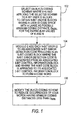
- FIG. 1 there is shown a flow chart of the method of the present invention.
- the method of the present invention will be discussed in the context of a wireless communication system that complies with the UMTS HSDPA standard (currently being developed) where the system transmits control information over a shared signaling channel (i.e., HS-SCCH) to various users of the system. It is clear, however, that the method of the present invention is applicable to other communication systems (wireless and wireline) that transmit signaling information over a signaling channel to various users.
- the error detection coding used is a UMTS standard 16 bit CRC.
- the values for N, K and I for the current UMTS HSDPA standard will be used in the discussion to follow. It should be well understood, however, that the method of the present invention is not limited to any particular values of N, K and I. Generally, N, K and I are integers equal to 1 or greater.
- step 100 an (N, K, D MIN ) coding scheme is selected such that for the particular values of K and N, the minimum coding distance ( D MIN ) between the resulting N-bit coded user ID blocks is as large as possible.
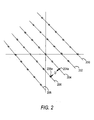
- the concept of coding distance is shown graphically in FIG. 2 where the set of all possible 21-bit blocks of control information or code space is mapped along a line where each line represents a particular user ID value applied to the code space of the control information.
- each of the code spaces 200-208 contains all of the possible values or codes of the control information. Since the control information contains 21 bits, the total number of possible codes is 2 21 .
- the 10-bit blocks of user IDs have a similar code space, but the total number of possible codes for the user IDs is 2 10 .
- 16-bit CRC codes are generated from the 21-bit blocks of control information in a well known fashion.
- the method of the present invention is not limited to using CRC codes as error detection codes. Other error detection coding schemes can be used with the method of the present invention.
- the CRC codes are combined with the coded user ID blocks to yield coded blocks.
- the 16-bit CRC codes are modulo 2 added (exclusive-OR operation) to associated 16-bit coded user ID blocks resulting in 16-bit coded blocks having a code space similar to that shown in FIG. 2 but whose coding distance may be less than 4 for some or all corresponding codes.
- the 16-bit coded blocks are appended to their associated 21-bit blocks of control information to yield codewords having a codespace shown in FIG. 2 where some or all of the corresponding codewords can have a coding distance (D) of less than 4.
- D coding distance
- D MIN integers with values of 1 or greater.
- the extended Hamming code is modified as follows.
- the (16, 10, 4) extended Hamming coding scheme is actually a (16, 11, 4) coding scheme since Hamming coding does not have a (16, 10, 4) coding scheme.
- the (16, 11, 4) coding scheme is obtained by converting in some manner the 10 user ID bits to 11 user ID bits and inputting them into the (16, 11, 4) extending Hamming coding scheme.
- the coding scheme structure is shown in FIG. 3. Referring to FIG. 3, coder 300 is shown comprising three coding functions 302, 304 and 306. Function 302 pads a 10 bit user ID with an extra bit (1 or 0) in any position.
- the resulting 11-bit block is applied to a (16, 11, 4) extended Hamming coding function 304 which yields a 16-bit user ID block that is applied to code rotator 306.
- Code rotator 306 rotates the codespace of the resulting 16-bit user ID block to reduce the number of pairs of codewords (or corresponding codewords) in the overall code space of 2 31 of FIG 2 having a coding distance of less than 4.
- the rotation of the codespace is the translation of the entire codespace by a certain angle.
- the rotation of the code space and the padding of the input 10 bits with a 1 or 0 bit in any position are adjustments to be made in the (16, 10, 4) coding scheme to reduce the occurrence of pairs of corresponding codewords in the overall code space of 2 31 of FIG 2 having coding distances of less than 4.
- a trial and error or more sophisticated search methods can be applied to determine which bit value to pad at which position and which rotation to perform that will tend to lead to a reduction in the occurrences of coding distances of less than 4.
- there are three degrees of freedom (value of pad bit, location of pad bit, amount of rotation performed on code space) that can be adjusted and by trial and error or more sophisticated search to create an overall codespace with a relatively small number of pairwise (corresponding codewords) coding distances of less than 4.
- coder 300 is modulo 2 added (with adder 308; exclusive-OR operation) to a 16-bit CRC generated from an associated 21-bit control information block resulting in a 16-bit user specific coded block which is appended to its associated 21-bit control information block and transmitted over the HS-SCCH to be decoded by its intended user.
- decoder 400 has coding functions 402, 404 and 406.
- a user Upon reception of control information over the HS-SCCH a user generates a 16-bit user specific coded block using padding function 402.
- the resulting 11-bit user ID is applied to extended Hamming coder 404 which generates a 16-bit vector.
- the 16-bit vector is applied to code rotator 406 which rotates the codespace and yields a 16 bit coded user ID codeword.
- the output of decoder 400 is applied to modulo 2 adder 408 along with the 16-bit received codeword.
- the User IDs match, their sum that is the part of the modulo 2 addition that yields zero (cancels out) and the result of the modulo 2 addition is the received version of the standard 16 bit CRC corresponding to the transmitted information block.
- the received information block's CRC is computed and checked against the received version of the CRC, they should match (i.e. add to zero) if the codeword received is intended for this user and there are no undetected errors due to channel degradation in the information or CRC part. If there is no match the received codeword is discarded and no decoding of the accompanying data traffic channel is done.
- the resulting overall code space of 2 31 codewords that are transmitted is such that there is a smaller likelihood that an unintended user would attempt to decode a received codeword. Therefore, the probability of false alarms is significantly reduced.
Claims (8)
- Verfahren zum Erzeugen von kodierter Benutzeridentifikationsinformation, hierin im Folgenden als Benutzer-ID bezeichnet, die mit Zeichengabeinformation über gemeinsam genutzte Zeichengabekanäle an Benutzer eines Kommunikationssystems übertragen werden sollen, wobei das Verfahren die folgenden Schritte umfasst:Anwenden eines (N, K, D MIN )-Fehlererkennungskodierungsschemas auf einen Satz von Benutzer-IDs, die jeweils K Bits aufweisen, so dass jeder resultierende kodierte Benutzer-ID-Informationsblock N Bits und einen Koderaum aufweist, der eine Mindestkodierungsdistanz von D MIN hat, wobei D MIN für bestimmte Werte von K und N so groß wie möglich ist und wobei D MIN , K und N ganze Zahlen sind, die gleich oder größer 1 sind und K < N;Vereinen jedes kodierten Benutzer-ID-Informationsblocks mit dessen zugehöriger Fehlererkennungskodeinformation mit einer Bitlänge von N, die aus dessen I Bit langer Zeichengabeinformation erzeugt wurde, um einen N Bit langen Block zu bilden, der an dessen zugehörige, I Bit lange Zeichengabeinformation angehängt ist, um einen kodierten Block mit einer Bitlänge von (I + N) zu erzeugen, wobei die kodierten Blocks mit einer Bitlänge von (I + N) eine Distanz D xy zueinander aufweisen;Modifizieren des (N, K, D MIN )-Kodierungsschemas, um das Auftreten von D xy < D MIN für die kodierten Benutzer-ID-Blocks zu reduzieren;Anwenden des modifizierten Kodierungsschemas auf die Benutzer-ID-Blocks und Vereinen dieser mit deren zugehörigen Fehlererkennungskodes; undÜbertragen von Kodewörtern, die die Zeichengabeinformation mit einer Bitlänge von I umfassen, die an die modifizierten und vereinten kodierten Blocks mit einer Bitlänge von N angehängt ist, über die gemeinsam genutzten Zeichengabekanäle an Benutzer des Kommunikationssystems.
- Verfahren nach Anspruch 1, wobei der Schritt des Vereinens der kodierten Benutzer-ID-Information mit Fehlererkennungskodeinformation Modulo 2 umfasst, das die kodierte Benutzerinformation zu dem Fehlererkennungskode addiert.
- Verfahren nach Anspruch 1, wobei der Schritt des Modifizierens des (N, K, D MIN )-Kodierungsschemas den Schritt des Auffüllens der K Bit langen Benutzer-ID-Information mit mindestens einem Bit und/oder des Drehens der kodierten, N Bit langen Benutzer-ID-Information, bevor sie mit dem Fehlererkennungskode vereint wird, umfasst.
- Verfahren nach Anspruch 1, wobei die Zeichengabeinformation den UMTS-HSDPA-Standard (UMTS HSDPA = Universal Mobile Telecommunications System High Speed Downlink Packet Access) und K = 1, N = 16, I = 21 und D MIN = 4 erfüllt und wobei das Benutzer-ID-Kodierungsschema ein (16, 11, 4)-Kode ist, der durch Auffüllen mit Bit, gefolgt von einem erweitertem Hamming-Kode (15, 11, 4), gefolgt von Drehung erhalten wird, und der Fehlererkennungskode ein CRC-Kode ist.
- Verfahren nach Anspruch 1, wobei die Zeichengabeinformation den UMTS-HSDPA-Standard (UMTS HSDPA = Universal Mobile Telecommunications System High Speed Downlink Packet Access) und K = 1, N = 16, I = 21 und D MIN = 4 erfüllt und wobei das Benutzer-ID-Kodierungsschema ein (16, 11, 4)-Kode ist, der durch einen verkürzten Hamming-Kode (15, 10, 4), gefolgt von einem Auffüllen mit Bit auf das Drehung erfolgt, erhalten wird, und der Fehlererkennungskode ein CRC-Kode ist.
- Verfahren nach Anspruch 4, wobei die 10 Bit lange Benutzer-ID-Information an einer Stelle in dem 10 Bit langen Block mit einem 1- oder 0-Bit aufgefüllt wird, was darauf abzielt, das Auftreten von benutzerspezifischen übereinstimmenden kodierten Blocks insgesamt mit einer Kodierungsdistanz von weniger als 4 zu reduzieren.
- Verfahren nach Anspruch 5, wobei die 15 Bit lange, teilweise kodierte Benutzer-ID-Information an einer Stelle in dem 15 Bit langen Block mit einem 1- oder 0-Bit aufgefüllt wird, um das Auftreten von benutzerspezifischen übereinstimmenden kodierten Blocks insgesamt mit einer Kodierungsdistanz von weniger als 4 zu reduzieren.
- Verfahren nach den Ansprüchen 4 - 7, wobei die resultierende 16 Bit lange kodierte Benutzer-ID-Information um einen bestimmten Winkel gedreht wird, bevor sie mit dem CRC-Kode vereint wird, um das Auftreten von benutzerspezifischen übereinstimmenden kodierten Blocks insgesamt mit einer Kodierungsdistanz von weniger als 4 zu reduzieren.
Applications Claiming Priority (2)
| Application Number | Priority Date | Filing Date | Title |
|---|---|---|---|
| US10/116,869 US6871313B2 (en) | 2002-04-05 | 2002-04-05 | Method for encoding a user identifier in a communication system |
| US116869 | 2002-04-05 |
Publications (3)
| Publication Number | Publication Date |
|---|---|
| EP1357691A2 EP1357691A2 (de) | 2003-10-29 |
| EP1357691A3 EP1357691A3 (de) | 2004-02-18 |
| EP1357691B1 true EP1357691B1 (de) | 2006-08-02 |
Family
ID=28674081
Family Applications (1)
| Application Number | Title | Priority Date | Filing Date |
|---|---|---|---|
| EP03251636A Expired - Fee Related EP1357691B1 (de) | 2002-04-05 | 2003-03-18 | Verfahren zur Kodierung eines Benutzeridentifikator in einem Kommunikationssystem |
Country Status (5)
| Country | Link |
|---|---|
| US (1) | US6871313B2 (de) |
| EP (1) | EP1357691B1 (de) |
| JP (1) | JP4304282B2 (de) |
| KR (1) | KR100994351B1 (de) |
| DE (1) | DE60307165T2 (de) |
Families Citing this family (24)
| Publication number | Priority date | Publication date | Assignee | Title |
|---|---|---|---|---|
| TWI287935B (en) * | 2002-05-01 | 2007-10-01 | Interdigital Tech Corp | Point to multi-point services using high speed shared channels in wireless communication systems |
| US7158635B2 (en) * | 2002-05-07 | 2007-01-02 | Interdigital Technology Corporation | Generation of user equipment identification specific scrambling code for the high speed shared control channel |
| US6973579B2 (en) | 2002-05-07 | 2005-12-06 | Interdigital Technology Corporation | Generation of user equipment identification specific scrambling code for the high speed shared control channel |
| US7007223B2 (en) * | 2002-06-30 | 2006-02-28 | Intel Corporation | Efficient method and apparatus for low latency forward error correction |
| US20040098651A1 (en) * | 2002-11-18 | 2004-05-20 | Rice Colm Marin | System and method for generating self-checking data having information content in an error detection field |
| US7200405B2 (en) | 2003-11-18 | 2007-04-03 | Interdigital Technology Corporation | Method and system for providing channel assignment information used to support uplink and downlink channels |
| US7054288B2 (en) * | 2004-02-13 | 2006-05-30 | Interdigital Technology Corporation | Method and apparatus for providing fast detection of a high speed shared control channel |
| JP4689316B2 (ja) * | 2005-03-28 | 2011-05-25 | 富士通株式会社 | 無線通信の下りリンクチャネルを伝送する制御情報のエラー検出方法及び移動端末 |
| US7613476B2 (en) * | 2006-06-02 | 2009-11-03 | Alcatel-Lucent Usa Inc. | Method and apparatus for path imbalance reduction in networks using high speed data packet access (HSDPA) |
| EP2528260A3 (de) | 2006-10-30 | 2014-07-30 | InterDigital Technology Corporation | Verfahren und Vorrichtung zur Hochgeschwindigkeitskodierung und -dekodierung gemeinsam genutzter Steuerkanaldaten |
| TW200832961A (en) * | 2007-01-23 | 2008-08-01 | Innovative Sonic Ltd | Method of detecting slot format of physical signaling channel in a wireless communications system and related apparatus |
| US8739013B2 (en) | 2007-09-28 | 2014-05-27 | Lg Electronics Inc. | Method for detecting control information in wireless communication system |
| KR101448309B1 (ko) | 2007-09-28 | 2014-10-08 | 엘지전자 주식회사 | 무선통신 시스템에서 하향링크 제어채널 모니터링 방법 |
| ES2393232T3 (es) | 2007-09-28 | 2012-12-19 | Lg Electronics Inc. | Procedimiento de detección de información de control en un sistema de comunicaciones inalámbricas |
| CN101494518B (zh) * | 2008-01-25 | 2011-12-21 | 车王电子股份有限公司 | 无线通讯的封包处理方法 |
| US8259643B2 (en) | 2009-02-13 | 2012-09-04 | Samsung Electronics Co., Ltd. | Apparatus and method for codeword to layer mapping in MIMO transmission wireless systems |
| US8806288B2 (en) * | 2009-03-13 | 2014-08-12 | Sharp Laboratories Of America, Inc. | Systems and methods for providing unequal error protection code design from probabilistically fixed composition codes |
| TWI459749B (zh) * | 2010-12-27 | 2014-11-01 | Ind Tech Res Inst | 數位資訊編碼方法、解碼方法、資訊傳播裝置及資訊管理裝置 |
| US9818131B2 (en) * | 2013-03-15 | 2017-11-14 | Liveramp, Inc. | Anonymous information management |
| DE102014213071A1 (de) * | 2014-07-04 | 2016-01-07 | Robert Bosch Gmbh | Verfahren und Vorrichtung zur Verarbeitung von Daten |
| CN112636871B (zh) * | 2015-05-13 | 2022-05-17 | 华为技术有限公司 | 网络节点、用户设备及其方法 |
| WO2018107430A1 (en) | 2016-12-15 | 2018-06-21 | Qualcomm Incorporated | Crc bits for joint decoding and verification of control information using polar codes |
| CN109274600B (zh) * | 2017-07-18 | 2022-04-29 | 华为技术有限公司 | 一种检测块发送和接收的方法、网络设备和系统 |
| CN114758728B (zh) * | 2022-06-15 | 2022-09-02 | 成都边界元科技有限公司 | 混合进制下产生最小海明距离的基因型标识及可视化方法 |
Family Cites Families (4)
| Publication number | Priority date | Publication date | Assignee | Title |
|---|---|---|---|---|
| JPH07110075B2 (ja) * | 1989-07-13 | 1995-11-22 | 日本電気株式会社 | コードレス電話方式 |
| US5430738A (en) * | 1991-01-31 | 1995-07-04 | Pioneer Electronic Corporation | Information transmission system for transmitting a digital information signal divided into packets with an information signal error diagnosis and correction function |
| FI90385C (fi) * | 1992-03-11 | 1994-01-25 | Salon Televisiotehdas Oy | Salattujen dataviestien tunnistus yksisuuntaisessa monipisteverkossa |
| US6201811B1 (en) * | 1998-03-24 | 2001-03-13 | Telefonaktiebolaget Lm Ericsson (Publ) | Transferring Identifier information in a telecommunications system |
-
2002
- 2002-04-05 US US10/116,869 patent/US6871313B2/en not_active Expired - Lifetime
-
2003
- 2003-03-18 DE DE60307165T patent/DE60307165T2/de not_active Expired - Lifetime
- 2003-03-18 EP EP03251636A patent/EP1357691B1/de not_active Expired - Fee Related
- 2003-03-27 JP JP2003087599A patent/JP4304282B2/ja not_active Expired - Fee Related
- 2003-03-28 KR KR1020030019511A patent/KR100994351B1/ko not_active IP Right Cessation
Also Published As
| Publication number | Publication date |
|---|---|
| EP1357691A3 (de) | 2004-02-18 |
| DE60307165D1 (de) | 2006-09-14 |
| JP2003333017A (ja) | 2003-11-21 |
| JP4304282B2 (ja) | 2009-07-29 |
| KR100994351B1 (ko) | 2010-11-16 |
| EP1357691A2 (de) | 2003-10-29 |
| KR20030080203A (ko) | 2003-10-11 |
| US20030192004A1 (en) | 2003-10-09 |
| US6871313B2 (en) | 2005-03-22 |
| DE60307165T2 (de) | 2007-07-05 |
Similar Documents
| Publication | Publication Date | Title |
|---|---|---|
| EP1357691B1 (de) | Verfahren zur Kodierung eines Benutzeridentifikator in einem Kommunikationssystem | |
| KR100730715B1 (ko) | 통신 시스템에서의 유연한 에러 보호 방법 | |
| US6839007B2 (en) | Inner coding of higher priority data within a digital message | |
| US8543867B2 (en) | Transmission of acknowledgement and negative acknowledgement in a wireless communication system | |
| EP1046245B1 (de) | Verfahren zur informationsübertragung und vorrichtung zum anwenden des verfahrens | |
| JP2002508640A (ja) | 通信システムにおける識別子情報送信方法及び装置 | |
| JPH09116440A (ja) | 誤り訂正符号化装置、誤り訂正復号化装置及び通信システム | |
| JP2002530007A (ja) | 遠隔通信システムにおいて高品質伝送を提供するための方法および装置 | |
| EP2137863B1 (de) | Mehrfach-paketquellenbestätigung | |
| CN108631792B (zh) | 一种极化码编译码方法及装置 | |
| AU2010346412A1 (en) | Technique of encoding HARQ feedback information with two separate codewords with unequal error protection for DTX and ACK/NACK | |
| JP5309017B2 (ja) | 無線通信ネットワークにおける符号語上での情報の符号化 | |
| JP4768324B2 (ja) | 無線通信機器 | |
| AU2008242513B2 (en) | Method and apparatus for indicating a temporary block flow using a piggybacked ACK/NACK field | |
| WO2003085874A1 (en) | Generation of a block coded terminal identifier | |
| EP1287618B1 (de) | Verfahren und apparat zur rückgewinnung von besonderen bits eines besonderen rahmens | |
| KR100667738B1 (ko) | 무선 패킷 송수신 장치 및 그 방법 | |
| US6678854B1 (en) | Methods and systems for providing a second data signal on a frame of bits including a first data signal and an error-correcting code | |
| WO2009075507A1 (en) | Method of error control | |
| US6553065B1 (en) | Mobile station employing CRC verification using decoding reliability and methods therefor | |
| GB2387303A (en) | Mobile terminal identification/addressing | |
| US5892464A (en) | Message encoding technique for communication systems | |
| US20010027536A1 (en) | Methods in a communication system | |
| CN112367143B (zh) | 一种基于喷泉码的抗干扰编码传输方法 | |
| WO2022262030A1 (zh) | 通信方法和通信装置 |
Legal Events
| Date | Code | Title | Description |
|---|---|---|---|
| PUAI | Public reference made under article 153(3) epc to a published international application that has entered the european phase |
Free format text: ORIGINAL CODE: 0009012 |
|
| 17P | Request for examination filed |
Effective date: 20030328 |
|
| AK | Designated contracting states |
Kind code of ref document: A2 Designated state(s): AT BE BG CH CY CZ DE DK EE ES FI FR GB GR HU IE IT LI LU MC NL PT SE SI SK TR |
|
| AX | Request for extension of the european patent |
Extension state: AL LT LV MK RO |
|
| PUAL | Search report despatched |
Free format text: ORIGINAL CODE: 0009013 |
|
| AK | Designated contracting states |
Kind code of ref document: A3 Designated state(s): AT BE BG CH CY CZ DE DK EE ES FI FR GB GR HU IE IT LI LU MC NL PT SE SI SK TR |
|
| AX | Request for extension of the european patent |
Extension state: AL LT LV MK RO |
|
| 17Q | First examination report despatched |
Effective date: 20040406 |
|
| AKX | Designation fees paid |
Designated state(s): DE FR GB |
|
| GRAP | Despatch of communication of intention to grant a patent |
Free format text: ORIGINAL CODE: EPIDOSNIGR1 |
|
| GRAS | Grant fee paid |
Free format text: ORIGINAL CODE: EPIDOSNIGR3 |
|
| GRAA | (expected) grant |
Free format text: ORIGINAL CODE: 0009210 |
|
| AK | Designated contracting states |
Kind code of ref document: B1 Designated state(s): DE FR GB |
|
| REG | Reference to a national code |
Ref country code: GB Ref legal event code: FG4D |
|
| REF | Corresponds to: |
Ref document number: 60307165 Country of ref document: DE Date of ref document: 20060914 Kind code of ref document: P |
|
| ET | Fr: translation filed | ||
| PLBE | No opposition filed within time limit |
Free format text: ORIGINAL CODE: 0009261 |
|
| STAA | Information on the status of an ep patent application or granted ep patent |
Free format text: STATUS: NO OPPOSITION FILED WITHIN TIME LIMIT |
|
| 26N | No opposition filed |
Effective date: 20070503 |
|
| REG | Reference to a national code |
Ref country code: GB Ref legal event code: 732E Free format text: REGISTERED BETWEEN 20131121 AND 20131127 |
|
| REG | Reference to a national code |
Ref country code: FR Ref legal event code: CD Owner name: ALCATEL-LUCENT USA INC. Effective date: 20131122 |
|
| REG | Reference to a national code |
Ref country code: FR Ref legal event code: GC Effective date: 20140410 |
|
| REG | Reference to a national code |
Ref country code: FR Ref legal event code: RG Effective date: 20141015 |
|
| REG | Reference to a national code |
Ref country code: FR Ref legal event code: PLFP Year of fee payment: 13 |
|
| REG | Reference to a national code |
Ref country code: FR Ref legal event code: PLFP Year of fee payment: 14 |
|
| REG | Reference to a national code |
Ref country code: FR Ref legal event code: PLFP Year of fee payment: 15 |
|
| PGFP | Annual fee paid to national office [announced via postgrant information from national office to epo] |
Ref country code: DE Payment date: 20170322 Year of fee payment: 15 Ref country code: FR Payment date: 20170322 Year of fee payment: 15 |
|
| PGFP | Annual fee paid to national office [announced via postgrant information from national office to epo] |
Ref country code: GB Payment date: 20170322 Year of fee payment: 15 |
|
| REG | Reference to a national code |
Ref country code: DE Ref legal event code: R119 Ref document number: 60307165 Country of ref document: DE |
|
| GBPC | Gb: european patent ceased through non-payment of renewal fee |
Effective date: 20180318 |
|
| PG25 | Lapsed in a contracting state [announced via postgrant information from national office to epo] |
Ref country code: DE Free format text: LAPSE BECAUSE OF NON-PAYMENT OF DUE FEES Effective date: 20181002 |
|
| PG25 | Lapsed in a contracting state [announced via postgrant information from national office to epo] |
Ref country code: GB Free format text: LAPSE BECAUSE OF NON-PAYMENT OF DUE FEES Effective date: 20180318 |
|
| PG25 | Lapsed in a contracting state [announced via postgrant information from national office to epo] |
Ref country code: FR Free format text: LAPSE BECAUSE OF NON-PAYMENT OF DUE FEES Effective date: 20180331 |