EP1357645B1 - Intelligenter Verbindungsstecker für einen Datenbus - Google Patents
Intelligenter Verbindungsstecker für einen Datenbus Download PDFInfo
- Publication number
- EP1357645B1 EP1357645B1 EP20030007841 EP03007841A EP1357645B1 EP 1357645 B1 EP1357645 B1 EP 1357645B1 EP 20030007841 EP20030007841 EP 20030007841 EP 03007841 A EP03007841 A EP 03007841A EP 1357645 B1 EP1357645 B1 EP 1357645B1
- Authority
- EP
- European Patent Office
- Prior art keywords
- connector
- plug
- housing
- cable
- connecting plug
- Prior art date
- Legal status (The legal status is an assumption and is not a legal conclusion. Google has not performed a legal analysis and makes no representation as to the accuracy of the status listed.)
- Expired - Lifetime
Links
Images


Classifications
-
- H—ELECTRICITY
- H01—ELECTRIC ELEMENTS
- H01R—ELECTRICALLY-CONDUCTIVE CONNECTIONS; STRUCTURAL ASSOCIATIONS OF A PLURALITY OF MUTUALLY-INSULATED ELECTRICAL CONNECTING ELEMENTS; COUPLING DEVICES; CURRENT COLLECTORS
- H01R13/00—Details of coupling devices of the kinds covered by groups H01R12/70 or H01R24/00 - H01R33/00
- H01R13/66—Structural association with built-in electrical component
- H01R13/665—Structural association with built-in electrical component with built-in electronic circuit
Definitions
- the invention relates to a connector for connecting an input / output unit, as an actuator, a sensor or the like. To a machine control with a central data bus according to the preamble of claim 1.
- connection boxes in the data bus of a machine control, which as bus nodes, collect the connection cables of connected actuators and sensors. For this purpose it is necessary, each actuator and sensor over an own cable with the Connection box to connect. This requires a high material usage and leads to thick wire harnesses that collect in appropriate cable ducts and channels are.
- a wiring harness is known in which a connector connect multiple actuators or sensors to a common data bus are.
- the connector has a looped data bus to to be connected via other connectors actuators and / or sensors. To start up such a data bus must have a correct address assignment be ensured to ensure trouble-free operation.
- the invention is based on the object, a simple connection of sensors and / or actuators to a central data bus of a machine control with safer Provide address assignment.
- a first connector is the connector with the incoming Cable connected, which is looped through to a second connector on which following units can be connected.
- the connector has a connection for the connection to the associated input / output unit, wherein the connection via an arranged in the housing of the connector electronics to the looped cable is connected. This creates on the one hand the possibility via the electronics the connection corresponding to the connected I / O unit head for.
- the intelligent connector recognizes the in the housing integrated electronics the connected unit and binds the unit accordingly the individual wires of the cable to the data bus.
- the user can do the same Connector for connecting sensors as well as for connecting actuators to use.
- a simple addressing is made possible when starting the system.
- the power supply of the following intelligent connector interrupted by the electronic switch. After the first Connector on the cable of the data bus through the machine control is addressed and the actuator or sensor connected to it via this address System is assigned, the electronic switch is closed, so that the next Connector in the row of cable is powered. Now the next connector addressed in the same way and after completed Addressing turn closed the provided in this connector electronic switch. In this way one after the other all connected to a data bus Sensors and actuators addressed and assigned with their address in the system.
- the housing of the connector according to Art a connector strip is formed.
- the plug is preferred as Multipole valve plug formed and serves the connection an actuator unit formed by a valve terminal is.
- the electronics in the housing of the connector is advantageous poured, in particular sealed, so that even under harsh environmental conditions a mechanical Damage to the electronics or influences by dirt, Solvent or the like. Are safely avoided. It corresponds the material with which the electronics in the housing is potted, preferably the housing material of the connector.
- the so solid designed connector has a mounting hole, which integrates into the housing is.
- the cast-in electronics are provided with a light-emitting diode, in the wall of the connector housing as a visual display serves.
- About the electronics can be a self-diagnosis both the connected input / output unit made as well as the incoming and the - Continuing cables are monitored.
- the plug connection in side view in the shape of a T. or a Y formed, wherein the plug connection the foot of the T and the Y forms and the connectors the ends the crossbeam of the T or the two upper ends of the Y represent.
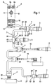
- the connector 1 shown in Figs. 1 to 3 is used the connection of input / output units (I / O units), such as an actuator 2, 4 or a sensor 3, 5 to a central Data bus 6 to be connected via connector 6a.
- I / O units input / output units
- Each of the input / output units 2, 3, 4, 5 is above the Connector 1 with a multi-core electrical Cable 7 connected leading to a junction box 8, the as a bus node 9 a plurality of I / O units via Plug 10 connects to the data bus 6.
- connection box 8 for the power supply of the sensors 3, 5 and actuators 2, 4 is provided via the connection box 8.
- the necessary operating voltage U actuator and U sensor is also supplied via the cable 7, which is designed in particular as a six-core cable 7.
- the housing 12 of the connector 1 a first connector 20 for an incoming cable 21st and a second connector 30 for a continuing Cable 31 on.
- a first connector 20 for an incoming cable 21st and a second connector 30 for a continuing Cable 31 on.
- a second connector 30 for a continuing Cable 31 on.
- the housing 12 of the connector 1 further has a Plug-in connection 40, to which an I / O unit 2, 3, 4, 5 connected.
- the plug connection 40th directly to the housing 13 of the sensor 3,5 or the Housing 14 of the actuator 2.4 be plugged.
- the connector 1 is thus directly on the housing 13, 14 of the I / O unit kept plugged.
- the plug connection 40 is electrically connected to a housing 12 arranged electronics 15 to the looped cable. 7 connected. Via a central microprocessor 16 is the plug connection 40 is configured, the electronics 15 independently detects whether a sensor 3, 5 or an actuator 2, 4 connected. Accordingly, the connection lines 17 switched so that the user only the intelligent connector with the sensor 3,5 or Actuator 2.4 has to connect and further adjustment measures are not necessary.
- the connector 1 can - with otherwise the same training Housing 12 - designed as T-connector be (Fig. 2) or the shape of a Y (Fig. 3) have. Thus, a suitable plug can be selected for each location become.
- Fig. 1 can with the intelligent connector 1 to a connector 10 of the connection box 8 of the bus node 9 more than one actuator or sensor connected become.
- the bus and power cable 7 is passed through each connector 1 looped through, so that on the cable. 7 parallel multiple sensors 3, 5 and actuators 2, 4 operated can be. It is noteworthy that on the same cable both input units such as sensors and output units how actuators can be connected mixed.
- the intelligent Connector 1 with distance to the sensor 5 or to arrange actuator 4, wherein the distance via a corresponding Connecting cable 18 and 19 to bridge. So even in tight installation conditions intelligent Connector 1 can be used.
- a mounting hole 45 is provided by a fastening screw or the like. Fastening element can be performed.
- the electronics 15 is designed so that the microprocessor 16 shows an optical display in the form of a light-emitting diode 25 controls, wherein the light emitting diode expediently in the wall of the Housing 12 of the connector 1 is inserted. Thereby can be displayed on the connector 1, if the connected actuator 2, 4 or sensor 3, 5 malfunctions shows. At the same time can on the LED 25 the proper condition of the continuation cable is displayed become. The user can do so without expensive technical Measures through a check passage along the cable 7 determine if and where errors occur.
- connection lines 17 are connected to an input module 28, which is controlled by the microprocessor 16.
- electronic switches 27 and an output module 29 are the Connecting lines 17 also as outputs to switch.
- the electronics 15 in the housing of the Pour in connector 1 is to compensate for tolerances on the LED applied a drop of clear silicone.
- the LED may not be complete enclose, so that the visual recognizability of outside is guaranteed.
- the measure, the LED or another optical indication before the encapsulation of the electronics to provide a drop of silicone is for itself in manufacturing technology of particular importance. The thought the application of a silicone drop is also independent from the present invention of the connector can be used advantageously in production technology.
- the individual sensors 3, 5 and actuators 2, 4 are in Data bus 6 detected by own addresses, with their own Addresses when commissioning the control system from Assigned to the system.
- the power supply of the microprocessor 16 is between the incoming connector 20 and the electronic switch 23 tapped, so that only the first connector 1 in the cable 7 is supplied with power is.
- the electronic switch 23 via the Microprocessor 16 is driven and closed, so that the next connector 1 in the row of cable 7 with Voltage is supplied.
- the last connector 1 terminates the cable 7. Accordingly, its housing 12 'only one connector 20 'for the incoming cable 21' and a Plug connection 40 'for the sensor 3 on. The continuing Plug connection is omitted.
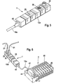
- the Connector 1 in the form of a terminal block designed, with one behind the other at one end in a row the connector 20 for the incoming cable 21st and the connector 30 for the continuation cable 31st are provided.
- the connector 20 is as a plug, the connector 30 designed as a socket.
- the free end 41 carries a connector 44.
- the connector 44 is preferably a multipole valve plug trained and serves the connection with a valve terminal trained actuator 4.
- the valve terminal consists from several, in the embodiment eight next to each other arranged switching valves 45, which in a common Valve bank 46 are held.
- connection cable 19a can be different connector systems connected to the different valve manufacturer become.
- Fig. 4 integrated in the terminal block 1 Electronics allows electrical wire break detection. Each connected channel is individually shorted supervised. The maximum number of channels is in the embodiment sixteen.
- An error eg. B. short circuit or wire break, is from the electronics via a z. B. red LED 25 displayed on the top of the housing 12a. additionally Each error can also be displayed individually as plain text on the internal system or higher-level system.
Landscapes
- Engineering & Computer Science (AREA)
- Microelectronics & Electronic Packaging (AREA)
- Details Of Connecting Devices For Male And Female Coupling (AREA)
Description
- Fig. 1
- eine schematische Ansicht eines Busknotens mit daran angeschlossenen Sensoren und Aktoren,
- Fig. 2
- in vergrößerter Darstellung einen erfindungsgemäßen Verbindungsstecker in T-Form,
- Fig. 3
- in vergrößerter Darstellung einen erfindungsgemäßen Verbindungsstecker in Y-Form,
- Fig. 4
- in schematischer Darstellung eine im Gehäuse des Verbindungssteckers integrierte aktive Elektronik,
- Fig. 5
- in perspektivische Darstellung einen Verbindungsstecker in Form einer Anschlussleiste mit einem Anschlusskabel,
- Fig. 6
- eine schematische Darstellung eines an einen Datenbus angeschlossenen Verbindunssteckers in Form einer Anschlussleiste mit einer angeschlossenen Ventilinsel.
Claims (10)
- Verbindungsstecker zum Anschluß einer E/A-Einheit, wie eines Aktors (2, 4), eines Sensors (3, 5) oder dgl. an eine Maschinensteuerung mit einem zentralen Datenbus (6), wobei die E/A-Einheit (2, 3, 4, 5) über den Verbindungsstecker (1) mit einem mehradrigen elektrischen Kabel (7) zu verbinden ist, das zu einem Busknoten (9) führt, wobei das Gehäuse (12, 12a) des Verbindungssteckers (1) eine erste Steckverbindung (20) für ein ankommendes Kabel (21) und eine zweite Steckverbindung (30) für ein weiterführendes Kabel (31) aufweist, wobei das ankommende Kabel (21) zum weiterführenden Kabel (31) durchgeschleift ist und das Gehäuse (12, 12a) einen Anschluß (40) für die E/A-Einheit (2, 3, 4, 5) aufweist, und der Anschluß (40) über eine im Gehäuse (12, 12a) des Verbindungssteckers (1) angeordnete Elektronik (15) an das durchgeschleifte Kabel (7) angeschlossen ist, wobei die Elektronik (15) einen elektronischen Schalter (23) umfaßt, der die Spannungsversorgung zur Steckverbindung (30) des weiterführenden Kabels (31) unterbricht und der elektronische Schalter (23) von der Elektronik (15) dann geschlossen ist, wenn dem Verbindungsstecker (1) von der Maschinensteuerung eine Adresse zugeordnet ist.
- Verbindungsstecker nach Anspruch 1,
dadurch gekennzeichnet, daß das Gehäuse (12a) nach Art einer Steckerleiste und der Anschluß (40) als aus dem Gehäuse (12a) führendes Kabel (19a) ausgebildet ist, dessen freies äußeres Ende (41) einen mehrpoligen Anschlußstecker (44) trägt, der vorzugsweise als Multipolventilstecker ausgebildet ist. - Verbindungsstecker nach Anspruch 1, dadurch gekennzeichnet, daß der Anschluß (40) als im Gehäuse (12) gehaltener Steckanschluß ausgebildet ist.
- Verbindungsstecker nach einem der Ansprüche 1 bis 3,
dadurch gekennzeichnet, daß die Elektronik (15) im Gehäuse (12) des Verbindungssteckers (1) eingegossen, insbesondere dicht eingegossen ist. - Verbindungsstecker nach einem der Ansprüche 1 bis 4,
dadurch gekennzeichnet, daß im Gehäuse (12) eine Befestigungsöffnung (45) integriert ist. - Verbindungsstecker nach einem der Ansprüche 1 bis 5,
dadurch gekennzeichnet, daß in der Wand des Gehäuses (12) eine optische Anzeige, insbesondere eine Leuchtdiode (25) angeordnet ist. - Verbindungsstecker nach Anspruch 6,
dadurch gekennzeichnet, daß die Leuchtdiode (25) vor dem Eingießen der Elektronik mit einem Tropfen Silikon benetzt ist. - Verbindungsstecker nach einem der Ansprüche 1 bis 7,
dadurch gekennzeichnet, daß das Gehäuse (12) mit den Steckverbindungen (20, 30) und dem Steckanschluß (40) in Seitenansicht etwa die Form eines T oder Y aufweist. - Verbindungsstecker nach einem der Ansprüche 1 bis 8,
dadurch gekennzeichnet, daß der Verbindungsstecker (1) unmittelbar auf das Gehäuse (12) der E/A-Einheit (2, 3, 4, 5) aufgesteckt ist. - Verbindungsstecker nach einem der Ansprüche 1 bis 9,
dadurch gekennzeichnet, daß die Elektronik (15) den elektronischen Schalter (23) im Ruhezustand unterbricht.
Priority Applications (1)
| Application Number | Priority Date | Filing Date | Title |
|---|---|---|---|
| EP20030007841 EP1357645B1 (de) | 2002-04-15 | 2003-04-05 | Intelligenter Verbindungsstecker für einen Datenbus |
Applications Claiming Priority (3)
| Application Number | Priority Date | Filing Date | Title |
|---|---|---|---|
| EP02008525 | 2002-04-15 | ||
| EP02008525 | 2002-04-15 | ||
| EP20030007841 EP1357645B1 (de) | 2002-04-15 | 2003-04-05 | Intelligenter Verbindungsstecker für einen Datenbus |
Publications (2)
| Publication Number | Publication Date |
|---|---|
| EP1357645A1 EP1357645A1 (de) | 2003-10-29 |
| EP1357645B1 true EP1357645B1 (de) | 2005-08-03 |
Family
ID=28793200
Family Applications (1)
| Application Number | Title | Priority Date | Filing Date |
|---|---|---|---|
| EP20030007841 Expired - Lifetime EP1357645B1 (de) | 2002-04-15 | 2003-04-05 | Intelligenter Verbindungsstecker für einen Datenbus |
Country Status (1)
| Country | Link |
|---|---|
| EP (1) | EP1357645B1 (de) |
Families Citing this family (4)
| Publication number | Priority date | Publication date | Assignee | Title |
|---|---|---|---|---|
| DE102005049483B4 (de) * | 2005-10-13 | 2007-10-18 | Ifm Electronic Gmbh | Elektrischen Stecker und Verfahren zur dezentralen Speicherung der Parameter eines Sensors |
| CN103809467B (zh) | 2012-11-05 | 2016-09-28 | 泰科电子(上海)有限公司 | 智能连接器 |
| CN108075322B (zh) * | 2016-11-11 | 2019-10-29 | 泰科电子(上海)有限公司 | 智能连接器 |
| DE102020124502A1 (de) | 2020-09-21 | 2022-03-24 | HELLA GmbH & Co. KGaA | Adapter mit einem ersten Steckverbinderteil zur elektrischen und zur mechanischen Verbindung mit einem Kabel und einem zweiten Steckverbinderteil zur elektrischen und zur mechanischen Verbindung mit einem elektrischen und/oder elektronischen Gerät |
Family Cites Families (3)
| Publication number | Priority date | Publication date | Assignee | Title |
|---|---|---|---|---|
| EP0807999A1 (de) * | 1996-05-17 | 1997-11-19 | Siemens Aktiengesellschaft | Energieverteilungssystem |
| AU1269499A (en) * | 1997-10-07 | 1999-04-27 | Electronics Development Corporation | Transducer assembly with smart connector |
| US6522515B1 (en) * | 1999-01-08 | 2003-02-18 | Littelfuse, Inc. | Data and power connector port |
-
2003
- 2003-04-05 EP EP20030007841 patent/EP1357645B1/de not_active Expired - Lifetime
Also Published As
| Publication number | Publication date |
|---|---|
| EP1357645A1 (de) | 2003-10-29 |
Similar Documents
| Publication | Publication Date | Title |
|---|---|---|
| EP0879445B1 (de) | Einrichtung zur eigensicheren signalanpassung | |
| EP1174781B1 (de) | Einrichtung zur Signalübertragung | |
| EP1840682B1 (de) | Elektrisches Feldgerät und Erweiterungsmodul zum Einstecken in das elektrisches Feldgerät | |
| EP2204586B1 (de) | Elektropneumatisches Modulsystem aus anreihbaren Einzelmodulen | |
| EP0275992A2 (de) | Maschinenanlage mit mehreren Aktoren | |
| DE19832561A1 (de) | Einheit zum Steuern von Elektromotoren | |
| EP2187722A2 (de) | Ein-/ Ausgabemodul für ein Automatisierungsgerät | |
| EP2710619B1 (de) | Systemverkabelung für mehrfachrelaisanordnung | |
| EP0710064A1 (de) | Feldbusanschlussmodul | |
| EP1244184B1 (de) | Verbindungssystem zum Anschluss von Wägezellen | |
| EP2258153B1 (de) | Elektrisches baukastenmodulsystem mit einem variabel einsetzbaren feldbusmodul | |
| DE4323440A1 (de) | Elektronisches Gerät, insbesondere Automatisierungsgerät | |
| DE19803042C2 (de) | Modul zum Anschluß eines Aktuators oder Sensors | |
| EP1039589B1 (de) | Verteiler zum Verbinden von Aktoren und/oder Sensoren | |
| EP1921328B1 (de) | Druckluftwartungsvorrichtung | |
| EP0068482A1 (de) | Steuerungssystem, insbesondere für automatische Fertigungsanlagen | |
| DE102006010640A1 (de) | Elektronisches Steuerungssystem, Kabelstrang und Stecker | |
| EP0984169B1 (de) | Ventilanordnung mit mindestens einer aus mehreren elektrisch betätigbaren Ventilen bestehenden Ventileinheit | |
| DE10019860C1 (de) | Verfahren und Einrichtung zum Prüfen von Kabelbäumen | |
| EP1357645A1 (de) | Intelligenter Verbindungsstecker für einen Datenbus | |
| EP0487761B1 (de) | Kleinmotor, Verfahren zur Herstellung desselben und Verwendung desselben | |
| DE10150641B4 (de) | Verbindungssystem zum Anschluss von Wägezellen | |
| WO1996011441A1 (de) | Modul für ein aktuator-sensor-interface-system | |
| EP1531524A1 (de) | Elektrischer Steckverbinder | |
| EP0891008A1 (de) | Energieverteilungssystem |
Legal Events
| Date | Code | Title | Description |
|---|---|---|---|
| PUAI | Public reference made under article 153(3) epc to a published international application that has entered the european phase |
Free format text: ORIGINAL CODE: 0009012 |
|
| AK | Designated contracting states |
Kind code of ref document: A1 Designated state(s): AT BE BG CH CY CZ DE DK EE ES FI FR GB GR HU IE IT LI LU MC NL PT RO SE SI SK TR |
|
| AX | Request for extension of the european patent |
Extension state: AL LT LV MK |
|
| 17P | Request for examination filed |
Effective date: 20040419 |
|
| AKX | Designation fees paid |
Designated state(s): AT BE BG CH CY CZ DE DK EE ES FI FR GB GR HU IE IT LI LU MC NL PT RO SE SI SK TR |
|
| 17Q | First examination report despatched |
Effective date: 20040707 |
|
| GRAP | Despatch of communication of intention to grant a patent |
Free format text: ORIGINAL CODE: EPIDOSNIGR1 |
|
| GRAS | Grant fee paid |
Free format text: ORIGINAL CODE: EPIDOSNIGR3 |
|
| GRAA | (expected) grant |
Free format text: ORIGINAL CODE: 0009210 |
|
| AK | Designated contracting states |
Kind code of ref document: B1 Designated state(s): AT BE BG CH CY CZ DE DK EE ES FI FR GB GR HU IE IT LI LU MC NL PT RO SE SI SK TR |
|
| PG25 | Lapsed in a contracting state [announced via postgrant information from national office to epo] |
Ref country code: IT Free format text: LAPSE BECAUSE OF FAILURE TO SUBMIT A TRANSLATION OF THE DESCRIPTION OR TO PAY THE FEE WITHIN THE PRESCRIBED TIME-LIMIT;WARNING: LAPSES OF ITALIAN PATENTS WITH EFFECTIVE DATE BEFORE 2007 MAY HAVE OCCURRED AT ANY TIME BEFORE 2007. THE CORRECT EFFECTIVE DATE MAY BE DIFFERENT FROM THE ONE RECORDED. Effective date: 20050803 Ref country code: TR Free format text: LAPSE BECAUSE OF FAILURE TO SUBMIT A TRANSLATION OF THE DESCRIPTION OR TO PAY THE FEE WITHIN THE PRESCRIBED TIME-LIMIT Effective date: 20050803 Ref country code: IE Free format text: LAPSE BECAUSE OF FAILURE TO SUBMIT A TRANSLATION OF THE DESCRIPTION OR TO PAY THE FEE WITHIN THE PRESCRIBED TIME-LIMIT Effective date: 20050803 Ref country code: EE Free format text: LAPSE BECAUSE OF FAILURE TO SUBMIT A TRANSLATION OF THE DESCRIPTION OR TO PAY THE FEE WITHIN THE PRESCRIBED TIME-LIMIT Effective date: 20050803 Ref country code: CZ Free format text: LAPSE BECAUSE OF FAILURE TO SUBMIT A TRANSLATION OF THE DESCRIPTION OR TO PAY THE FEE WITHIN THE PRESCRIBED TIME-LIMIT Effective date: 20050803 Ref country code: FI Free format text: LAPSE BECAUSE OF FAILURE TO SUBMIT A TRANSLATION OF THE DESCRIPTION OR TO PAY THE FEE WITHIN THE PRESCRIBED TIME-LIMIT Effective date: 20050803 Ref country code: SK Free format text: LAPSE BECAUSE OF FAILURE TO SUBMIT A TRANSLATION OF THE DESCRIPTION OR TO PAY THE FEE WITHIN THE PRESCRIBED TIME-LIMIT Effective date: 20050803 Ref country code: GB Free format text: LAPSE BECAUSE OF FAILURE TO SUBMIT A TRANSLATION OF THE DESCRIPTION OR TO PAY THE FEE WITHIN THE PRESCRIBED TIME-LIMIT Effective date: 20050803 Ref country code: SI Free format text: LAPSE BECAUSE OF FAILURE TO SUBMIT A TRANSLATION OF THE DESCRIPTION OR TO PAY THE FEE WITHIN THE PRESCRIBED TIME-LIMIT Effective date: 20050803 Ref country code: RO Free format text: LAPSE BECAUSE OF FAILURE TO SUBMIT A TRANSLATION OF THE DESCRIPTION OR TO PAY THE FEE WITHIN THE PRESCRIBED TIME-LIMIT Effective date: 20050803 Ref country code: NL Free format text: LAPSE BECAUSE OF FAILURE TO SUBMIT A TRANSLATION OF THE DESCRIPTION OR TO PAY THE FEE WITHIN THE PRESCRIBED TIME-LIMIT Effective date: 20050803 |
|
| REG | Reference to a national code |
Ref country code: GB Ref legal event code: FG4D Free format text: NOT ENGLISH |
|
| REG | Reference to a national code |
Ref country code: CH Ref legal event code: EP |
|
| REG | Reference to a national code |
Ref country code: CH Ref legal event code: NV Representative=s name: ISLER & PEDRAZZINI AG |
|
| REG | Reference to a national code |
Ref country code: IE Ref legal event code: FG4D Free format text: LANGUAGE OF EP DOCUMENT: GERMAN |
|
| REF | Corresponds to: |
Ref document number: 50300889 Country of ref document: DE Date of ref document: 20050908 Kind code of ref document: P |
|
| PG25 | Lapsed in a contracting state [announced via postgrant information from national office to epo] |
Ref country code: BG Free format text: LAPSE BECAUSE OF FAILURE TO SUBMIT A TRANSLATION OF THE DESCRIPTION OR TO PAY THE FEE WITHIN THE PRESCRIBED TIME-LIMIT Effective date: 20051103 Ref country code: DK Free format text: LAPSE BECAUSE OF FAILURE TO SUBMIT A TRANSLATION OF THE DESCRIPTION OR TO PAY THE FEE WITHIN THE PRESCRIBED TIME-LIMIT Effective date: 20051103 Ref country code: GR Free format text: LAPSE BECAUSE OF FAILURE TO SUBMIT A TRANSLATION OF THE DESCRIPTION OR TO PAY THE FEE WITHIN THE PRESCRIBED TIME-LIMIT Effective date: 20051103 Ref country code: SE Free format text: LAPSE BECAUSE OF FAILURE TO SUBMIT A TRANSLATION OF THE DESCRIPTION OR TO PAY THE FEE WITHIN THE PRESCRIBED TIME-LIMIT Effective date: 20051103 |
|
| PG25 | Lapsed in a contracting state [announced via postgrant information from national office to epo] |
Ref country code: ES Free format text: LAPSE BECAUSE OF FAILURE TO SUBMIT A TRANSLATION OF THE DESCRIPTION OR TO PAY THE FEE WITHIN THE PRESCRIBED TIME-LIMIT Effective date: 20051114 |
|
| PG25 | Lapsed in a contracting state [announced via postgrant information from national office to epo] |
Ref country code: PT Free format text: LAPSE BECAUSE OF FAILURE TO SUBMIT A TRANSLATION OF THE DESCRIPTION OR TO PAY THE FEE WITHIN THE PRESCRIBED TIME-LIMIT Effective date: 20060103 |
|
| NLV1 | Nl: lapsed or annulled due to failure to fulfill the requirements of art. 29p and 29m of the patents act | ||
| PG25 | Lapsed in a contracting state [announced via postgrant information from national office to epo] |
Ref country code: HU Free format text: LAPSE BECAUSE OF FAILURE TO SUBMIT A TRANSLATION OF THE DESCRIPTION OR TO PAY THE FEE WITHIN THE PRESCRIBED TIME-LIMIT Effective date: 20060204 |
|
| GBV | Gb: ep patent (uk) treated as always having been void in accordance with gb section 77(7)/1977 [no translation filed] |
Effective date: 20050803 |
|
| REG | Reference to a national code |
Ref country code: IE Ref legal event code: FD4D |
|
| PG25 | Lapsed in a contracting state [announced via postgrant information from national office to epo] |
Ref country code: AT Free format text: LAPSE BECAUSE OF NON-PAYMENT OF DUE FEES Effective date: 20060405 |
|
| ET | Fr: translation filed | ||
| PG25 | Lapsed in a contracting state [announced via postgrant information from national office to epo] |
Ref country code: BE Free format text: LAPSE BECAUSE OF NON-PAYMENT OF DUE FEES Effective date: 20060430 Ref country code: MC Free format text: LAPSE BECAUSE OF NON-PAYMENT OF DUE FEES Effective date: 20060430 |
|
| PLBI | Opposition filed |
Free format text: ORIGINAL CODE: 0009260 |
|
| 26 | Opposition filed |
Opponent name: ABB PATENT GMBH Effective date: 20060503 |
|
| PLAX | Notice of opposition and request to file observation + time limit sent |
Free format text: ORIGINAL CODE: EPIDOSNOBS2 |
|
| PLAF | Information modified related to communication of a notice of opposition and request to file observations + time limit |
Free format text: ORIGINAL CODE: EPIDOSCOBS2 |
|
| PLBB | Reply of patent proprietor to notice(s) of opposition received |
Free format text: ORIGINAL CODE: EPIDOSNOBS3 |
|
| REG | Reference to a national code |
Ref country code: CH Ref legal event code: PCAR Free format text: ISLER & PEDRAZZINI AG;POSTFACH 1772;8027 ZUERICH (CH) |
|
| BERE | Be: lapsed |
Owner name: MURR-ELEKTRONIK G.M.B.H. Effective date: 20060430 |
|
| PG25 | Lapsed in a contracting state [announced via postgrant information from national office to epo] |
Ref country code: LU Free format text: LAPSE BECAUSE OF NON-PAYMENT OF DUE FEES Effective date: 20060405 |
|
| PLCK | Communication despatched that opposition was rejected |
Free format text: ORIGINAL CODE: EPIDOSNREJ1 |
|
| PG25 | Lapsed in a contracting state [announced via postgrant information from national office to epo] |
Ref country code: CY Free format text: LAPSE BECAUSE OF FAILURE TO SUBMIT A TRANSLATION OF THE DESCRIPTION OR TO PAY THE FEE WITHIN THE PRESCRIBED TIME-LIMIT Effective date: 20050803 |
|
| PLBN | Opposition rejected |
Free format text: ORIGINAL CODE: 0009273 |
|
| STAA | Information on the status of an ep patent application or granted ep patent |
Free format text: STATUS: OPPOSITION REJECTED |
|
| 27O | Opposition rejected |
Effective date: 20081006 |
|
| PGFP | Annual fee paid to national office [announced via postgrant information from national office to epo] |
Ref country code: DE Payment date: 20120420 Year of fee payment: 10 Ref country code: CH Payment date: 20120420 Year of fee payment: 10 |
|
| PGFP | Annual fee paid to national office [announced via postgrant information from national office to epo] |
Ref country code: FR Payment date: 20120507 Year of fee payment: 10 |
|
| REG | Reference to a national code |
Ref country code: CH Ref legal event code: PL |
|
| PG25 | Lapsed in a contracting state [announced via postgrant information from national office to epo] |
Ref country code: LI Free format text: LAPSE BECAUSE OF NON-PAYMENT OF DUE FEES Effective date: 20130430 Ref country code: DE Free format text: LAPSE BECAUSE OF NON-PAYMENT OF DUE FEES Effective date: 20131101 Ref country code: CH Free format text: LAPSE BECAUSE OF NON-PAYMENT OF DUE FEES Effective date: 20130430 |
|
| REG | Reference to a national code |
Ref country code: FR Ref legal event code: ST Effective date: 20131231 |
|
| REG | Reference to a national code |
Ref country code: DE Ref legal event code: R119 Ref document number: 50300889 Country of ref document: DE Effective date: 20131101 |
|
| PG25 | Lapsed in a contracting state [announced via postgrant information from national office to epo] |
Ref country code: FR Free format text: LAPSE BECAUSE OF NON-PAYMENT OF DUE FEES Effective date: 20130430 |