EP1357084A1 - Système pour le réformage de combustible - Google Patents
Système pour le réformage de combustible Download PDFInfo
- Publication number
- EP1357084A1 EP1357084A1 EP03005128A EP03005128A EP1357084A1 EP 1357084 A1 EP1357084 A1 EP 1357084A1 EP 03005128 A EP03005128 A EP 03005128A EP 03005128 A EP03005128 A EP 03005128A EP 1357084 A1 EP1357084 A1 EP 1357084A1
- Authority
- EP
- European Patent Office
- Prior art keywords
- flowrate
- carbon monoxide
- reformer
- monoxide oxidizer
- oxygen
- Prior art date
- Legal status (The legal status is an assumption and is not a legal conclusion. Google has not performed a legal analysis and makes no representation as to the accuracy of the status listed.)
- Withdrawn
Links
Images


Classifications
-
- C—CHEMISTRY; METALLURGY
- C01—INORGANIC CHEMISTRY
- C01B—NON-METALLIC ELEMENTS; COMPOUNDS THEREOF; METALLOIDS OR COMPOUNDS THEREOF NOT COVERED BY SUBCLASS C01C
- C01B3/00—Hydrogen; Gaseous mixtures containing hydrogen; Separation of hydrogen from mixtures containing it; Purification of hydrogen
- C01B3/02—Production of hydrogen or of gaseous mixtures containing a substantial proportion of hydrogen
- C01B3/32—Production of hydrogen or of gaseous mixtures containing a substantial proportion of hydrogen by reaction of gaseous or liquid organic compounds with gasifying agents, e.g. water, carbon dioxide, air
- C01B3/34—Production of hydrogen or of gaseous mixtures containing a substantial proportion of hydrogen by reaction of gaseous or liquid organic compounds with gasifying agents, e.g. water, carbon dioxide, air by reaction of hydrocarbons with gasifying agents
- C01B3/38—Production of hydrogen or of gaseous mixtures containing a substantial proportion of hydrogen by reaction of gaseous or liquid organic compounds with gasifying agents, e.g. water, carbon dioxide, air by reaction of hydrocarbons with gasifying agents using catalysts
-
- B—PERFORMING OPERATIONS; TRANSPORTING
- B01—PHYSICAL OR CHEMICAL PROCESSES OR APPARATUS IN GENERAL
- B01J—CHEMICAL OR PHYSICAL PROCESSES, e.g. CATALYSIS OR COLLOID CHEMISTRY; THEIR RELEVANT APPARATUS
- B01J19/00—Chemical, physical or physico-chemical processes in general; Their relevant apparatus
- B01J19/0006—Controlling or regulating processes
- B01J19/0013—Controlling the temperature of the process
-
- C—CHEMISTRY; METALLURGY
- C01—INORGANIC CHEMISTRY
- C01B—NON-METALLIC ELEMENTS; COMPOUNDS THEREOF; METALLOIDS OR COMPOUNDS THEREOF NOT COVERED BY SUBCLASS C01C
- C01B3/00—Hydrogen; Gaseous mixtures containing hydrogen; Separation of hydrogen from mixtures containing it; Purification of hydrogen
- C01B3/02—Production of hydrogen or of gaseous mixtures containing a substantial proportion of hydrogen
- C01B3/32—Production of hydrogen or of gaseous mixtures containing a substantial proportion of hydrogen by reaction of gaseous or liquid organic compounds with gasifying agents, e.g. water, carbon dioxide, air
- C01B3/34—Production of hydrogen or of gaseous mixtures containing a substantial proportion of hydrogen by reaction of gaseous or liquid organic compounds with gasifying agents, e.g. water, carbon dioxide, air by reaction of hydrocarbons with gasifying agents
- C01B3/48—Production of hydrogen or of gaseous mixtures containing a substantial proportion of hydrogen by reaction of gaseous or liquid organic compounds with gasifying agents, e.g. water, carbon dioxide, air by reaction of hydrocarbons with gasifying agents followed by reaction of water vapour with carbon monoxide
-
- C—CHEMISTRY; METALLURGY
- C01—INORGANIC CHEMISTRY
- C01B—NON-METALLIC ELEMENTS; COMPOUNDS THEREOF; METALLOIDS OR COMPOUNDS THEREOF NOT COVERED BY SUBCLASS C01C
- C01B3/00—Hydrogen; Gaseous mixtures containing hydrogen; Separation of hydrogen from mixtures containing it; Purification of hydrogen
- C01B3/50—Separation of hydrogen or hydrogen containing gases from gaseous mixtures, e.g. purification
- C01B3/56—Separation of hydrogen or hydrogen containing gases from gaseous mixtures, e.g. purification by contacting with solids; Regeneration of used solids
- C01B3/58—Separation of hydrogen or hydrogen containing gases from gaseous mixtures, e.g. purification by contacting with solids; Regeneration of used solids including a catalytic reaction
- C01B3/583—Separation of hydrogen or hydrogen containing gases from gaseous mixtures, e.g. purification by contacting with solids; Regeneration of used solids including a catalytic reaction the reaction being the selective oxidation of carbon monoxide
-
- B—PERFORMING OPERATIONS; TRANSPORTING
- B01—PHYSICAL OR CHEMICAL PROCESSES OR APPARATUS IN GENERAL
- B01J—CHEMICAL OR PHYSICAL PROCESSES, e.g. CATALYSIS OR COLLOID CHEMISTRY; THEIR RELEVANT APPARATUS
- B01J2219/00—Chemical, physical or physico-chemical processes in general; Their relevant apparatus
- B01J2219/00049—Controlling or regulating processes
- B01J2219/00191—Control algorithm
-
- C—CHEMISTRY; METALLURGY
- C01—INORGANIC CHEMISTRY
- C01B—NON-METALLIC ELEMENTS; COMPOUNDS THEREOF; METALLOIDS OR COMPOUNDS THEREOF NOT COVERED BY SUBCLASS C01C
- C01B2203/00—Integrated processes for the production of hydrogen or synthesis gas
- C01B2203/02—Processes for making hydrogen or synthesis gas
- C01B2203/0205—Processes for making hydrogen or synthesis gas containing a reforming step
- C01B2203/0227—Processes for making hydrogen or synthesis gas containing a reforming step containing a catalytic reforming step
-
- C—CHEMISTRY; METALLURGY
- C01—INORGANIC CHEMISTRY
- C01B—NON-METALLIC ELEMENTS; COMPOUNDS THEREOF; METALLOIDS OR COMPOUNDS THEREOF NOT COVERED BY SUBCLASS C01C
- C01B2203/00—Integrated processes for the production of hydrogen or synthesis gas
- C01B2203/02—Processes for making hydrogen or synthesis gas
- C01B2203/0283—Processes for making hydrogen or synthesis gas containing a CO-shift step, i.e. a water gas shift step
-
- C—CHEMISTRY; METALLURGY
- C01—INORGANIC CHEMISTRY
- C01B—NON-METALLIC ELEMENTS; COMPOUNDS THEREOF; METALLOIDS OR COMPOUNDS THEREOF NOT COVERED BY SUBCLASS C01C
- C01B2203/00—Integrated processes for the production of hydrogen or synthesis gas
- C01B2203/04—Integrated processes for the production of hydrogen or synthesis gas containing a purification step for the hydrogen or the synthesis gas
- C01B2203/0435—Catalytic purification
- C01B2203/044—Selective oxidation of carbon monoxide
-
- C—CHEMISTRY; METALLURGY
- C01—INORGANIC CHEMISTRY
- C01B—NON-METALLIC ELEMENTS; COMPOUNDS THEREOF; METALLOIDS OR COMPOUNDS THEREOF NOT COVERED BY SUBCLASS C01C
- C01B2203/00—Integrated processes for the production of hydrogen or synthesis gas
- C01B2203/04—Integrated processes for the production of hydrogen or synthesis gas containing a purification step for the hydrogen or the synthesis gas
- C01B2203/0465—Composition of the impurity
- C01B2203/047—Composition of the impurity the impurity being carbon monoxide
-
- C—CHEMISTRY; METALLURGY
- C01—INORGANIC CHEMISTRY
- C01B—NON-METALLIC ELEMENTS; COMPOUNDS THEREOF; METALLOIDS OR COMPOUNDS THEREOF NOT COVERED BY SUBCLASS C01C
- C01B2203/00—Integrated processes for the production of hydrogen or synthesis gas
- C01B2203/16—Controlling the process
- C01B2203/1614—Controlling the temperature
- C01B2203/1619—Measuring the temperature
-
- C—CHEMISTRY; METALLURGY
- C01—INORGANIC CHEMISTRY
- C01B—NON-METALLIC ELEMENTS; COMPOUNDS THEREOF; METALLOIDS OR COMPOUNDS THEREOF NOT COVERED BY SUBCLASS C01C
- C01B2203/00—Integrated processes for the production of hydrogen or synthesis gas
- C01B2203/16—Controlling the process
- C01B2203/169—Controlling the feed
Definitions
- This invention relates to a fuel reforming system.
- the fuel reforming system disclosed in JP8-273690A published by the Japanese Patent Office in 1996 generates reformate gas containing hydrogen by a reforming reaction and a partial oxidation reaction in a reformer using air (gas containing oxygen) and raw fuel.
- the hydrogen-rich reformate gas contains carbon monoxide.
- the carbon monoxide poisons the electrode catalyst in a polymer electrolyte fuel cell, which contains platinum, and reduces its activity.
- JP8-273690A discloses that the reformer is controlled so that the carbon monoxide concentration in the reformate gas is reduced based on the carbon monoxide concentration detected by a carbon monoxide detector.
- control would be performed to reduce the temperature of the reformer when the carbon monoxide concentration in the reformate gas exceeds a predetermined value. This is because, when the temperature of the reformer falls, the flowrate of generated reformate gas decreases, and it is thought that the carbon monoxide in the reformate gas also decreases.
- the processing performance of the carbon monoxide oxidation catalyst is not taken into account. If the temperature of the reformer is merely reduced when an increase of carbon monoxide in the reformate gas supplied to the fuel cell is detected, it may take too much time until the carbon monoxide in the reformate gas supplied to the fuel cell is reduced, or the temperature of the reformer may fall too much.
- the processing performance of the carbon monoxide oxidation catalyst reaches its limit, it is impossible to prevent the increase of the carbon monoxide by using a carbon monoxide oxidizer when the carbon monoxide in the reformate gas supplied to the fuel cell increases, so all of the increased carbon monoxide must be reduced by reducing the reformer temperature.
- the processing performance of the carbon monoxide oxidation catalyst has a margin, an amount of carbon monoxide corresponding to this margin could be removed by the carbon monoxide oxidizer, so the temperature drop of the reformer could be reduced accordingly.
- the carbon monoxide in the reformate gas supplied to the fuel cell has increased, to remove the increased carbon monoxide in just proportion, it is preferable to vary the drop in temperature of the reformer according to the processing performance of the carbon monoxide oxidation catalyst.
- the processing performance of the carbon monoxide oxidation catalyst was not taken into account, so for example if the magnitude of the temperature drop of the reformer were set corresponding to the situation where the processing performance of the carbon monoxide oxidation catalyst has a margin, the temperature drop of the reformer would not be sufficient if the processing performance of the carbon monoxide oxidation catalyst had reached its limit.
- untreated carbon monoxide would continue to flow into the fuel cell for some time and the power-generating characteristics of the fuel cell might be impaired.
- the temperature drop of the reformer would be excessive (the temperature drop of the reformer would fall unnecessarily) when the processing performance of the carbon monoxide oxidation catalyst has a margin.
- this invention provides a fuel reforming system, comprising a reformer which generates reformate gas containing hydrogen by a reforming reaction and a partial oxidation reaction using an oxygen-containing gas and raw fuel, carbon monoxide oxidizer containing a carbon monoxide oxidation catalyst which removes carbon monoxide contained in the reformate gas by a shift reaction between carbon monoxide in the reformate gas and water, and a preferential oxidation reaction which oxidizes a remaining carbon monoxide not oxidized in the shift reaction using the oxygen-containing gas, and supplies the reformate gas from which the carbon monoxide has been removed to a fuel cell, a cooling device which cools a heat liberated by the shift reaction and preferential oxidation reaction in the carbon monoxide oxidizer by a coolant, and a controller.
- the controller functions to determine whether the carbon monoxide oxidizer is in a marginal operation state where a processing performance of the carbon monoxide oxidation catalyst has reached a limit, and perform an avoidance processing to avoid the marginal operation state of the carbon monoxide oxidation catalyst.
- Fig. 1 is a schematic view of a fuel reforming system according to the present invention.
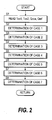
- Fig. 2 is a flowchart of a process for determining the seven cases.
- Fig. 3 is a flowchart of a determining process of Case 1.
- Fig. 4 is a flowchart of a determining process of Case 2.
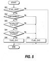
- Fig. 5 is a flowchart of a determining process of Case 3.
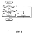
- Fig. 6 is a flowchart of a determining process of Case 4.
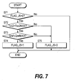
- Fig. 7 is a flowchart of a determining process of Case 5.
- Fig. 8 is a flowchart of a determining process of Case 6.
- Fig. 9 is a flowchart of a determining process of Case 7.
- Fig. 10 is a flowchart of processing to avoid a marginal operation state of a carbon monoxide oxidizer.
- Figs. 11 and 12 are flowcharts of a first avoidance processing.
- Fig. 13 is a characteristic diagram of a target raw fuel flowrate of a vaporizer.
- Fig. 14 is a characteristic diagram of a target air flowrate of a reformer.
- Fig. 15 is a characteristic diagram of a distribution ratio.
- Fig. 16 is a flowchart of a third avoidance processing.
- Fig. 17 is a flowchart of a fourth avoidance processing.
- Fig. 18 is a flowchart of a fifth avoidance processing.
- Fig. 19 is a flowchart of a sixth avoidance processing.
- Fig. 20 is a flowchart of a seventh avoidance processing.
- Fig. 21 is a schematic view of a reformer.
- Fig. 1 of the drawings shows a fuel reforming system according to this invention. Firstly, the basic construction and operation of this fuel reforming system will be described.
- Fig. 1 water in a water tank 2 and methanol in a fuel tank 3 are sent to a vaporizer 6 from a water feeder 4 and fuel feeder 5, and heated and vaporized to form a gaseous mixture of water and methanol (raw fuel vapor) which is sent to a reformer 8.
- the feeders 4, 5 basically comprise a pump and injector.
- the target values of the water flowrate and methanol flowrate are computed by a controller 31 based on the power required to be generated by a fuel cell 17.
- the controller 31 respectively controls flowrate control devices (injectors) in the feeders 4, 5 so that the respective target values are realized.
- the required power is computed based on the accelerator depression amount.
- Air gas containing oxygen
- a compressor 7 In order to supply all the air needed by the whole fuel cell system, rotation speed control of the compressor 7 is carried out by a flowrate controller 16 so that the compressor discharge flowrate detected by a flowrate sensor 15 is equal to the sum of the air flowrate supplied to the reformer 8, the air flowrate supplied to the carbon monoxide oxidizer 9, and the air flowrate needed by the fuel cell 17.
- a flowrate controller 16 For example, the non-interfering control system disclosed in JP2001-338659A published by the Japanese Patent Office in 2001 can be adopted for the control used by the flowrate controller 16.
- the reformer 8 performs the reforming reaction of the gaseous mixture of water and methanol with oxygen in the air, and generates hydrogen-rich reformate gas.
- the reformer 8 is operated under autothermal conditions under which the heat released by the partial oxidation reaction and the heat absorbed by the decomposition reaction of methanol are balanced.
- the flowrate of water vapor relative to the flowrate of methanol, and the oxygen flowrate in the air relative to the flowrate of methanol, will be effectively fixed.
- the reformer 8 is filled with a catalyst 8b which performs a partial oxidation reaction and a reforming reaction in a cylindrical container 8a, as shown in Fig. 21.
- a raw fuel inlet 8c and an air inlet 8d near to it are provided at one end, and a gas outlet 8e is provided at the other end. If all the air flowrate required for the partial oxidation reaction is supplied from the air inlet 8d, the catalyst temperature in the reformer 8 may exceed the target operating temperature Tm (for example, 400°C). For this reason, a middle air inlet 8f is provided further downstream than the air inlet 8d, and air is supplied from both the air inlet 8d and middle air inlet 8f.
- Tm target operating temperature
- target values are determined so that the air flowrate (hereafter, air inlet flowrate) from the air inlet 8d and the air flowrate from the middle air inlet 8f (hereafter, middle air flowrate) are optimal, the opening of the flow control valve 21 (air inlet flowrate regulator) is controlled so that the actual air inlet flowrate detected by a flowrate sensor 32 coincides with the target value, and the opening of a flow control valve 22 (middle air flowrate regulator) is controlled so that the actual middle air flowrate detected by a flowrate sensor 33 coincides with the target value.
- air inlet flowrate air inlet flowrate
- middle air flowrate middle air flowrate
- the hydrogen-rich reformate gas generated by the reformer 8 contains several % of carbon monoxide. This carbon monoxide poisons the electrode catalyst, which for example contains platinum, of the polymer electrolyte fuel cell 17, and reduces its activity. Therefore, the reformate gas must be supplied to the fuel cell 17 after the carbon monoxide has been reduced to several tens of ppm by the carbon monoxide oxidizer 9 which comprises a shift reactor and a PROX reactor (preferential oxidation reactor).
- Reformate gas containing several % of carbon monoxide is sent to the shift reactor, and carbon monoxide is reduced by the catalyst in the shift reaction.
- the operating temperature of the shift reactor is 200°C-300°C, and produces reformate gas which contains 0. several percent of carbon monoxide due to a thermodynamic chemical equilibrium.
- the reformate gas wherein carbon monoxide was reduced by the shift reaction is sent to the PROX reactor, and carbon monoxide is further reduced to several tens of ppm by a catalytic oxidation reaction (exothermic). Oxygen required for the catalytic oxidation reaction is supplied as air from the compressor 7.
- a carbon monoxide sensor 35 is provided immediately downstream of the compressor 7.
- the target value of the air flowrate supplied to the carbon monoxide oxidizer 9 is computed so that the actual concentration of carbon monoxide detected by the sensor 35 is below a predetermined value determined by the specification of the fuel cell 17.
- the opening of a flow control valve 23 is controlled by the flowrate controller 11 so that the actual air flowrate detected by a flowrate sensor 34 coincides with the target value.
- the carbon monoxide oxidizer 9 is cooled by a coolant from a cooler 12.
- a target value of the coolant flowrate supplied to the carbon monoxide oxidizer 9 is computed so that an inlet catalyst temperature Tco1 of the carbon monoxide oxidizer 9 detected by a temperature sensor 36 does not exceed a maximum value.
- the opening of a flow control valve 24 (coolant flowrate regulator) is controlled by a flowrate controller 14 so that the actual coolant flowrate detected by a flowrate sensor 37 coincides with this target value.
- Reformate gas wherein the carbon monoxide has been reduced to a very low concentration and the air from the compressor 7 are sent to a fuel electrode and air electrode of the fuel cell 17.
- the oxygen in the air and the hydrogen in the reformate gas are made to react electrochemically to generate power.
- reformate gas containing hydrogen which was not used for power generation and air containing oxygen which was not used for power generation are sent to and burned in a catalytic combustor 18.
- the obtained hot combustion gas is sent to a vaporizer 6, and is reused as energy to vaporize methanol and water.
- the fuel reforming system according to this embodiment is installed in a vehicle.
- the current extracted from the fuel cell 17 is passed via an inverter 19 to a vehicle drive motor 20.
- the inverter 19 and motor 20 are loads which consume the power generated by the fuel cell 17.
- the inlet catalyst temperature Tco1 is detected by the temperature sensor 36
- the outlet catalyst temperature Tco2 is detected by a temperature sensor 38
- the air flowrate Qcoa is detected by the flowrate sensor 34
- the coolant flowrate Qref is detected by the flowrate sensor 37, respectively.
- the carbon monoxide oxidizer 9 comprises the shift reactor and the PROX reactor.
- the shift reactor is disposed upstream, and the PROX reactor is disposed downstream.
- the inlet catalyst of the carbon monoxide oxidizer 9 denotes the catalyst which performs the shift reaction, and the outlet catalyst of the carbon monoxide oxidizer 9 denotes the catalyst which performs the PROX reaction.
- the carbon monoxide oxidizer 9 is in the marginal operation state when it is in one of the following seven situations. In any of these cases, avoidance processing corresponding to the case is performed to avoid the marginal operation state.
- Case 1 is the case where the coolant flowrate Qref to the carbon monoxide oxidizer 9 exceeds a maximum value QrefMAX , and the outlet catalyst temperature Tco2 of the carbon monoxide oxidizer 9 exceeds a maximum value Tco2MAX .
- the period during which the above two processes are performed is the predetermined period until the effect of a drop in raw fuel flowrate is evident, the reformate gas flowrate falls, and the carbon monoxide in the reformate gas decreases.
- the air flowrate to the reformer 8 is increased so that the flowrate ratio increases to the target flowrate ratio while the raw fuel flowrate is still reduced.
- Case 3 is the case where the coolant flowrate Qref supplied to the carbon monoxide oxidizer 9 exceeds the maximum value QrefMAX , the inlet catalyst temperature Tco1 of the carbon monoxide oxidizer 9 lies between the maximum value Tco1MAX and minimum value Tco1MIN , and the outlet catalyst temperature Tco2 of the carbon monoxide oxidizer 9 lies between the maximum value Tco2MAX and minimum value Tco2MIN.
- the marginal values of temperature and flowrate which appear in Cases 1-7 are determined as follows.
- the maximum value Tco1MAX and minimum value Tco1MIN of the inlet catalyst temperature Tco1 of the carbon monoxide oxidizer 9, and the maximum value Tco2MAX and minimum value Tco2MIN of the outlet catalyst temperature Tco2 of the carbon monoxide oxidizer 9, are determined by the volume of the carbon monoxide oxidizer 9, and by the heat resistance of the carbon monoxide oxidation catalyst in the carbon monoxide oxidizer 9.
- the maximum value QcoaMAX and the minimum value QcoaMIN of the air flowrate Qcoa supplied to the carbon monoxide oxidizer 9 are determined by the performance of the compressor 7.
- the maximum value QrefMAX and minimum value QrefMIN of coolant flowrate are determined according to the performance of the pump which discharges the coolant.
- the purpose of decreasing the air flowrate is different in Cases 1, 2, 3 and 4.
- the method of decreasing the air flowrate to the reformer 8 is made different as follows according to the difference in purpose.
- the middle air flowrate is reduced first and the air inlet flowrate is not changed.
- the air supplied from the middle air inlet 8f is the part which could not be supplied from the air inlet 8d since the inlet catalyst temperature of the reformer 8 would reach too high a temperature, and it has an auxiliary role. Therefore, when the air flowrate is decreased, the middle air flowrate, which performs an auxiliary role, is made to decrease. In this case, although the catalyst temperature near the air inlet 8d of the reformer 8 does not change, the catalyst temperature near the middle air inlet 8f falls. The middle air flowrate continues to decrease and eventually becomes zero. If further reduction of the air flowrate to the reformer 8 is required, the air inlet flowrate is decreased.
- the reduction of the air flowrate to the reformer 8 in Case 3 aims to maintain the raw fuel conversion rate in the reformer 8, and is treated identically to the reduction of the air flowrate to the reformer 8 in Cases 1 and 2.
- both the catalyst temperature near the air inlet 8d of the reformer 8, and the catalyst temperature near the middle air inlet 8f of the reformer 8 are lowered.
- both the air inlet flowrate and middle air flowrate are lowered.
- Fig. 2 determines which of the above seven cases should be applied, and is performed at a fixed interval (e.g., every 10 milliseconds).
- a step S1 the inlet catalyst temperature Tco1 and the outlet catalyst temperature Tco2 of the carbon monoxide oxidizer 9, and the air flowrate Qcoa to the carbon monoxide oxidizer 9 and the coolant flowrate Qref to the carbon monoxide oxidizer 9, are read.
- the inlet catalyst temperature Tco1 and outlet catalyst temperature Tco2 are detected by the temperature sensors 36, 38 (catalyst temperature detection means), the air flowrate Qcoa is detected by the flowrate sensor 34 (air flowrate detection means) and the coolant flowrate Qref is detected by the flowrate sensor 37 (coolant flowrate detection means).
- steps S2-S8 it is determined whether or not any of the seven above-mentioned cases apply in this order. When one of the cases does apply, a flag corresponding to this case is set to "1". There are seven flags FLAG_J1 - FLAG_J7 corresponding to the seven cases, and the initial value of all flags is "0.” When one of the cases applies, the flag corresponding to that case is set to "1.”
- Fig. 3 shows the subroutine of the step S2 of Fig. 2, and determines whether or not Case 1 applies.
- a step S31 the flag FLAG_J1 is observed.
- the routine proceeds to steps S32 and S33, the coolant flowrate Qref to the carbon monoxide oxidizer 9 is compared with its maximum value QrefMAX , and the outlet catalyst temperature Tco2 of the carbon monoxide oxidizer 9 is compared with its maximum value Tco2MAX, respectively.
- the routine proceeds from the step S31 to a step S36 from the next occasion, and the flag FLAG_E1 is observed.
- Fig. 4 is the subroutine of the step S3 of Fig. 2, and determines whether or not Case 2 applies.
- a step S41 the flag FLAG_J2 is observed.
- the routine proceeds to steps S42, S43, S44, the inlet catalyst temperature Tco1 of the carbon monoxide oxidizer 9 is compared with its minimum value Tco1MIN , the coolant flowrate Qref to the carbon monoxide oxidizer 9 is compared with its minimum value QrefMIN , and the air flowrate Qcoa to the carbon monoxide oxidizer 9 is compared with its minimum value QcoaMIN , respectively.
- the routine proceeds to the step S46, and the flag FLAG_J2 is set to "0."
- the routine proceeds from the step S41 to a step S47 from the next occasion, and the flag FLAG_E2 is observed.
- Fig. 5 shows the subroutine of the step S4 of Fig. 2, and determines whether or not Case 3 applies.
- a step S51 the flag FLAG_J3 is observed.
- the routine proceeds to steps S52, S53, S54, the coolant flowrate Qref to the carbon monoxide oxidizer 9 is compared with its maximum value QrefMAX , the inlet catalyst temperature Tco1 of the carbon monoxide oxidizer 9 is compared with its maximum value Tco1MAX and minimum value Tco1MIN , and the outlet catalyst temperature Tco2 of the carbon monoxide oxidizer 9 is compared with its maximum value Tco2MAX and minimum value Tco2MIN , respectively.
- the routine proceeds to a step S56 and the flag FLAG_J3 is set to "0."
- Fig. 6 shows the subroutine of the step S5 of Fig. 2, and determines whether or not Case 4 applies.
- a step S61 the flag FLAG_J4 is observed.
- the routine proceeds to a step S62, and the air flowrate Qcoa to the carbon monoxide oxidizer 9 is compared with its maximum value QcoaMAX .
- Fig. 7 shows the subroutine of the step S6 of Fig. 2, and determines whether or not Case 5 applies.
- a step S71 the flag FLAG_J5 is observed.
- the routine proceeds to steps S72 and S73, the outlet catalyst temperature Tco2 of the carbon monoxide oxidizer 9 is compared with its maximum value Tco2MAX , and the coolant flowrate Qref to the carbon monoxide oxidizer 9 is compared with its maximum value QrefMAX , respectively.
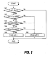
- Fig. 8 shows the subroutine of the step S7 of Fig. 2, and determines whether or not Case 6 applies.
- a step S81 the Flag FLAG_J6 is observed.
- the routine proceeds to steps S82, S83, S84, the inlet catalyst temperature Tco1 of the carbon monoxide oxidizer 9 is compared with its minimum value Tco1MIN , the coolant flowrate Qref to the carbon monoxide oxidizer 9 is compared with its minimum value QrefMIN and the air flowrate Qcoa to the carbon monoxide oxidizer 9 is compared with its minimum value QcoaMIN , respectively.
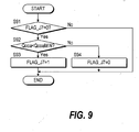
- Fig. 9 shows the subroutine of the step S7 of Fig. 2, and determines whether or not Case 7 applies.
- a step S91 the Flag FLAG_J7 is observed. As the initial value of flag FLAG_J7 is "0”, the routine proceeds to a step S92, and the air flowrate Qcoa to the carbon monoxide oxidizer 9 is compared with its minimum value QcoaMIN.
- Fig. 11 and Fig. 12 are for computing a target air inlet flowrate Qm1 and a target middle air flowrate Qm2 of the reformer 8 and a target raw fuel flowrate tQgen of the vaporizer 6 in the first avoidance processing.
- Fig. 11 and Fig. 12 are subroutines of the step S114 of Fig. 10, and are executed with an identical period to that of Fig. 10.
- the flowcharts of Fig. 11, Fig. 12 and the flowcharts of Fig. 16, Fig. 17, Fig. 18, Fig. 19 have been drawn up for the situation when the load does not fluctuate much.
- steps S121, S122 basic air flowrates (a basic air inlet flowrate Qm10 and a basic middle air flowrate Qm20 ) of the reformer 8 which give the optimal raw fuel conversion efficiency when none of the above seven cases apply (usual state), are computed.
- the target raw fuel flowrate tQgen [kg/min] of the vaporizer 6, the target air flowrate tQa [kg/min] of the reformer 8 and the distribution ratio Rd when the target air flowrate tQa is distributed between the air inlet 8d and middle air inlet 8f of the reformer 8, are read. These three values are calculated by looking up the tables shown in Fig. 13, Fig. 14 and Fig. 15, respectively.
- an inlet catalyst temperature Tkai1 of the reformer 8 is also read from a temperature sensor 39.
- the basic air inlet flowrate Qm10 and the basic middle air flowrate Qm20 are computed by the following equations (2) and (3) using the target air flowrate tQa and the distribution ratio Rd of the reformer 8:
- Qm10 tQa ⁇ Rd
- Qm20 tQa ⁇ (1 - Rd)
- a flag FLAG_A1 is observed.
- the routine proceeds to a step S124.
- the predetermined value ⁇ 1 is set to a value which obviously decreases the reformate gas flow of the reformer outlet, and also obviously decreases the carbon monoxide in the reformate gas proportionately.
- the predetermined value ⁇ 1 is determined based on experimental results.
- tQgen1 ⁇ Rqref1 which is the numerator of the right-hand side of equation (5), is the oxygen flowrate [kg/min] at the predetermined flowrate ratio Rqref1.
- the air flowrate [kg/min] is obtained by dividing this by 0.21, which is the oxygen proportion in air.
- the proportion of raw fuel and oxygen in the reformer 8 that is, the reaction state, changes, and the ratio of raw fuel changed into hydrogen-rich gas (conversion rate) changes. Due to this, the carbon monoxide contained in the reformate gas falls immediately.
- the predetermined flowrate ratio Rqref of equation (5) is determined by experiment or simulation beforehand so that the carbon monoxide in the reformate gas can be effectively reduced.
- this flowrate decrease dQa and the basic middle air flowrate Qm20 are compared.
- the flowrate decrease dQa is smaller than the basic middle air flowrate Qm20 , the flowrate decrease dQa can be achieved by decreasing the middle air flowrate, so the routine proceeds to a step S128 and a target middle air flowrate Qm2 is computed by the following equation (7):
- Qm2 Qm20 - dQa
- the basic air inlet flowrate Qm10 is set equal to the target air inlet flowrate Qm1 .
- the routine proceeds from the step S127 to a step S129, and the target middle air flowrate Qm2 is set to zero to achieve the flowrate decrease of Qm20 and the target air inlet flowrate Qm1 is computed by the following equation (8) to achieve the further flowrate decrease of dQa-Qm20 :
- Qm1 Qm10 - (dQa - Qm20)
- the computation of the target air inlet flowrate Qm1 and the target middle air flowrate Qm2 in the first avoidance processing is complete, so a timer t is started and the flag FLAG_A1 is set to "1" in steps S130, S131.
- Qm1 , Qm2, tQgen1 are moved to an output register.
- the timer t is for measuring the time from starting first avoidance processing. On startup, the timer t is reset to zero, and subsequently becomes larger as the time progresses.
- the opening of the flow control valve 21 is controlled so that the actual air inlet flowrate detected by the flowrate sensor 32 coincides with the target air inlet flowrate Qm1 .
- the opening of the flow control valve 22 is also controlled so that the actual middle air flowrate detected by the flowrate sensor 33 coincides with the target middle air flowrate Qm2 .
- the flow control valves 21, 22 may be replaced by flow control valves of the self-regulating type.
- flowrate sensors are built in, and when the target air flowrates Qm1 and Qm2 are supplied as inputs, the valve openings are driven automatically so that these values and the real flowrates detected by the built-in flowrate sensors coincide.
- the flowrate controllers (injectors) in the water and fuel feeders 4, 5 are controlled so that raw fuel is supplied to the reformer 8 at the computed target raw fuel flowrate tQgen .
- the routine proceeds from the step S123 to a step S133, and the timer t is compared with a predetermined value t0 (positive fixed value).
- the predetermined value t0 is set as the period until the effect of a drop of raw fuel flowrate due to the start of the first avoidance processing appears, causing a reduction of reformate gas flowrate, and the carbon monoxide in the reformate gas decreases.
- JP8-273690A published by the Japanese Patent Office in 1996 discloses the case when the unreacted material is methanol. t0 is determined from the result of experiment or simulation conducted beforehand.
- the routine proceeds to a step S134 and the present state is maintained. That is, the immediately preceding values of Qm1, Qm2, tQgen1 are taken as the present values, and the step S132 is performed.
- the immediately preceding value of Qm1 is denoted as Qm1z
- the immediately preceding value of Qm2 is denoted as Qm2z
- the immediately preceding value of tQgen1 is denoted as tQgen1z .
- the routine proceeds to the return processing of the step S133 to the step S135 and subsequent steps of Fig. 12.
- proportional integral operation is performed in a step S137 based on the temperature difference ⁇ T , and a feedback amount Qfb is computed.
- Qm10 when Qm10 is less than Qm1, Qm10 can be supplied by increasing the air inlet flowrate of the reformer 8, so the routine proceeds to a step S141 and Qm2 is set to zero.
- a step S142 the value of the target raw fuel flowrate tQgen1 of the vaporizer 6 is maintained, and a step S143 is performed.
- the routine proceeds from the step S135 to a step S144, the present air flowrate to the reformer 8 is maintained, the flag FLAG_A1 is set to "0" and the end flag FLAG_E1 is set to "1" in steps S145, S146 to prepare for the next occasion, and the routine proceeds to the steps S142, S143.
- the second avoidance processing is almost the same as the first avoidance processing, so a detailed description will be omitted.
- the names of the flags are changed in Fig. 11 and Fig. 12, i.e., in the second avoidance processing, the flag FLAG_A1 of the steps S123, S131, S145 is changed to a FLAG_A2, and the flag FLAG_E1 of the step S146 is changed to a FLAG_E2.
- Fig. 16 is for calculating the target air inlet flowrate Qm1 and the target middle air flowrate Qm2 of the reformer 8, and the target raw fuel flowrate tQgen of the vaporizer 6 in the third avoidance processing.
- Fig. 16 is the subroutine of the step S112 of Fig. 10, and is performed at the same interval as Fig. 10. Identical step numbers are attached to the same parts as those of Fig. 11 and Fig. 12.
- step S133 of Fig. 11 and the steps S135-S146 of Fig. 12 are not in Fig. 16. Further, in a step S151, reading of the inlet catalyst temperature Tkai1 of the reformer 8 is unnecessary.
- steps S152, S155 the names of the flags are different from those of the first avoidance processing to agree with the third avoidance processing.
- Fig. 17 is for computing the target air inlet flowrate Qm1 and the target middle air flowrate Qm2 of the reformer 8 in the fourth avoidance processing.
- Fig. 17 is the subroutine of the step S111 of Fig. 10 and is performed at the same interval as Fig. 10.
- a step S161 the target raw fuel flowrate tQgen of the vaporizer 6, the target air flowrate tQa of the reformer 8 the distribution ratio Rd , and the inlet catalyst temperature Tkai1 of the reformer 8, are read.
- the basic air inlet flowrate Qm10 and the basic middle air flowrate Qm20 are computed by the equations (2) and (3).
- a flag FLAG_A4 is observed.
- the routine proceeds from the step S163 to a step S169, and the inlet catalyst temperature Tkai1 of the reformer 8 and the target temperature Tm1 of the reformer 8 in the fourth avoidance processing are compared.
- Tkai1 is higher than Tm1 , so to further reduce the air flowrate to the reformer 8, the target air inlet flowrate Qm1 and the target middle air flowrate are decreased by the following equations (19), (20) in a step 170:
- Qm1 Qm1z -dQ1
- Qm2 Qm2z - dQ2
- Qm1z immediately preceding value of Qm1
- Qm2z immediately preceding value of Qm2
- step S168 is performed.
- step S170 If the step S170 is repeated and the air flowrate to the reformer 8 is reduced, the inlet catalyst temperature Tkai1 of the reformer 8 will eventually become less than the target temperature Tm1 of the reformer 8 in the fourth avoidance processing. When it becomes less than the target temperature Tm1 , the routine proceeds from the step S169 to a step S171, and the present air flowrate to the reformer 8 is maintained.
- Fig. 17 is performed with the same interval as Fig. 10, but as there is a response delay from when the air flowrate to the reformer 8 is reduced to when the result of this is reflected in the temperature, the interval of Fig. 17 may be made to differ from the interval of Fig. 10 taking account of the response delay.
- Fig. 18 is for calculating the target air inlet flowrate Qm1 and the target middle air flowrate Qm2 of the reformer 8, and the target coolant flowrate tQref to the carbon monoxide oxidizer 9, in the fifth avoidance processing.
- Fig. 18 is the subroutine of the step S110 in Fig. 10, and is performed with the same interval as Fig. 10.
- tQgen, tQa , the distribution ratio Rd, the inlet catalyst temperature Tco1 of the carbon monoxide oxidizer 9 detected by the temperature sensor 36 and the actual coolant flowrate Qref detected by the flowrate sensor 37, are read.
- the target air inlet flowrate Qm1 and the target middle air flowrate Qm2 are computed by the following equations (21), (22):
- Qm1 tQa ⁇ Rd
- Qm2 tQa ⁇ (1 - Rd)
- a flag FLAG_A5 is observed.
- Qm1, Qm2, tQref are moved to an output register in a step S186.
- the opening of the flowrate control valve 21 is controlled so that air flows at the target air inlet flowrate Qm1
- the opening of a flow control valve 22 is controlled so that air flows at the target middle air flowrate Qm2 .
- the operation of the temperature controller 13 is stopped and a command value is directly outputted to the flowrate controller 14 so that coolant is supplied at the computed target coolant flowrate tQref to the carbon monoxide oxidizer 9.
- the temperature controller 13 gives a command value to the flowrate controller 14 so that the inlet catalyst temperature Tco1 of the carbon monoxide oxidizer 9 is maintained at a predetermined value, e.g., a temperature lower than the maximum value Tco1 by a predetermined allowance, so to change the coolant flowrate to the carbon monoxide oxidizer 9, it would appear to be sufficient if the controller 31 gives a command to change the target temperature to the temperature controller 13.
- Case 5 applies and it is necessary to adjust the coolant flowrate, it means that the temperature control by the temperature controller 13 is not functioning well. For this reason, instead of changing the target temperature given to the temperature controller 13, the operation of the temperature controller 13 is stopped, and the target coolant flowrate tQref is output directly to the flowrate controller 14.
- the routine proceeds from the step S183 to a step S187, and the inlet catalyst temperature Tco1 of the carbon monoxide oxidizer 9 is compared with a predetermined temperature TcoA.
- step S189 the target air inlet flowrate Qm1 and the target middle air flowrate Qm2 of the reformer 8 are maintained in their present state, and the step S186 is performed.
- steps S188 and S186 are repeated and the coolant flowrate to the carbon monoxide oxidizer 9 is increased, the inlet catalyst temperature Tco1 eventually falls, and will fall to below the predetermined temperature TcoA .
- the routine proceeds from the step S187 to a step S190, the target coolant flowrate tQref at that time is maintained, and steps S189, S186 are performed.
- the flowchart of Fig. 18 is performed with the same interval as Fig. 10, but as there is a delay from when the coolant flowrate to the carbon monoxide oxidizer 9 is increased to when the result is reflected in the temperature, the interval of Fig. 18 may differ from that of Fig. 10 to take account of the delay.
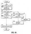
- Fig. 19 computes the target air inlet flowrate Qm1 and the target middle air flowrate Qm2 of the reformer 8, and the target coolant flowrate tQref to the carbon monoxide oxidizer 9, in the sixth avoidance processing.
- Fig 19 is the subroutine of the step S109 of Fig 10, and is executed at an identical interval to Fig. 10. Identical step numbers to those of Fig 18 are given to identical parts.
- a flag FLAG_A6 is observed.
- the routine proceeds from the step S201 to a step S204, and the inlet catalyst temperature Tco1 of the carbon monoxide oxidizer 9 is compared with a predetermined temperature TcoB .
- the predetermined temperature TcoB may for example be a value obtained by allowing a predetermined tolerance ⁇ 2 (positive fixed value) from the minimum value TcoMIN .
- TcoB TcoMIN + ⁇ 2
- step S189 the target air inlet flowrate Qm1 and target middle air flowrate Qm2 of the reformer 8 are maintained at their present values, and the step S186 is executed.
- the routine proceeds from the step S204 to the step S190, the target coolant flowrate tQref at that time is maintained, and the steps S189, S186 are executed.
- the flowchart of Fig. 19 is executed at an identical interval to Fig. 10, but as there is a delay until the decrease of flowrate to the carbon monoxide oxidizer 9 is reflected in the temperature, the interval of Fig 19 may differ from the interval of Fig. 10 to take account of this delay.
- the predetermined value ⁇ (steps S184, S188 of Fig. 18) which is the increment in the cooling flowrate per unit interval, and the predetermined value ⁇ (steps S202, S205 of Fig. 19) which is the decrement in the cooling flowrate per unit interval, may be identical or different.
- Fig. 20 describes the seventh avoidance processing.
- Fig. 20 is the subroutine of the step S108 of Fig. 10, and is executed at an identical interval to Fig. 10.
- step S211, S212 the raw fuel flowrate Qgen and air flowrate Qa to the reformer 8 are gradually reduced from their present values.
- step S213 power generation of the fuel cell 17 is stopped.
- the reason why the raw fuel flowrate and air flowrate are reduced at a predetermined variation rate is because, if the raw fuel flowrate Qgen and air flowrate Qa are suddenly reduced, the variation would be too large and the fuel reforming system would become unstable.
- the coolant flowrate Qref to the carbon monoxide oxidizer 9 is maintained without reduction (step S214).
- the carbon monoxide oxidizer 9 becomes capable of removing carbon monoxide. Hence, even if the carbon monoxide of the reformate gas sharply increases, the increased carbon monoxide can be removed due to the capacity of the carbon monoxide oxidizer 9 to remove the carbon monoxide. Specifically, the processing performance of the carbon monoxide oxidation catalyst is prevented from shifting to its limit, so untreated carbon monoxide is prevented from flowing into the fuel cell 17.
- the outlet temperature Tco2 of the carbon monoxide oxidizer 9 exceeds the maximum value Tco2MAX , the reaction in the carbon monoxide oxidation catalyst proceeds actively to the outlet so the carbon monoxide which should be removed is probably present up to the outlet. Also, if the coolant flowrate Qref exceeds the maximum value QrefMAX , further cooling cannot be performed. As carbon monoxide which should be removed is present up to the outlet and further cooling cannot be performed, the processing performance of the carbon monoxide oxidation catalyst reaches its limit, and even if air is then supplied to the carbon monoxide oxidizer 9 to cause an oxidation reaction (exothermic reaction), carbon monoxide cannot be removed.
- the raw fuel flowrate to the reformer 8 is reduced.
- the reformate gas flowrate at the reformer outlet falls, the carbon monoxide in the reformate gas falls, and the processing performance of the carbon monoxide oxidation catalyst returns to the state where there is some allowance compared to the limit (the marginal operation state of the carbon monoxide oxidizer 9 is avoided).
- the air flowrate to the reformer 8 is decreased so that the flowrate ratio becomes less than the target flowrate ratio, therefore the reaction state in the reformer 8 changes.
- the carbon monoxide in the reformate gas can be reduced more rapidly than by maintaining the flowrate ratio at the target flowrate ratio and reducing the raw fuel flowrate.
- the coolant flowrate Qref to the carbon monoxide oxidizer 9 falls below the minimum value QrefMIN , cooling is unnecessary although a certain amount of air is being supplied to the carbon monoxide oxidizer 9, and the inlet catalyst temperature Tco1 of the carbon monoxide oxidizer 9 falls below the minimum value Tco1MIN , it may be supposed that the carbon monoxide oxidation catalyst is not active, i.e., that the carbon monoxide oxidation catalyst has deteriorated (if the catalyst is active and the oxygen concentration in the vicinity of the inlet of the carbon monoxide oxidizer 9 is high, the catalyst temperature in the vicinity of the inlet would rise).
- the processing performance of the carbon monoxide oxidation catalyst reaches a limit, so even if air is then supplied to the carbon monoxide oxidizer 9 to cause an oxidation reaction (exothermic reaction), carbon monoxide cannot be removed.
- the raw fuel flowrate to the reformer 8 is reduced. Due to this, the reformate gas flowrate at the reformer outlet falls, the carbon monoxide in the reformate gas falls, and the processing performance of the carbon monoxide oxidation catalyst can be restored to a state where there is some allowance compared to the limit (the limited operation state of the carbon monoxide oxidizer is avoided).
- the air flowrate to the reformer 8 is decreased so that the flowrate ratio is less than the target flowrate ratio. Due to this, the reaction state in the reformer 8 changes, and the carbon monoxide in the reformate gas falls more rapidly than if the flowrate ratio were maintained at the target flowrate ratio and the raw fuel flowrate reduced.
- the conversion efficiency of the reformer 8 falls, and the amount of unreacted raw fuel remaining in the reformate gas at the reformer outlet increases. It may be expected that if this state continues for a long time, it will have an adverse effect on the fuel cell 17.
- the air flowrate to the reformer 8 is increased until the flowrate ratio coincides with the target flowrate ratio when the predetermined period, from when the drop in raw fuel flowrate has the effect of reducing the reformate gas flowrate until the carbon monoxide in the reformate gas decreases, has elapsed. Due to this, the conversion efficiency of the reformer 8 is restored, unreacted raw fuel in the reformate gas is reduced and an adverse effect on the fuel cell 17 is prevented.
- the raw fuel flowrate to the reformer 8 is reduced.
- the reformate gas flowrate at the reformer outlet falls, the carbon monoxide in the reformate gas falls, and the processing performance of the carbon monoxide oxidation catalyst can be restored to a state where there is some allowance compared to the limit (the marginal operation state of the carbon monoxide oxidizer is avoided).
- the air flowrate to the reformer 8 is decreased so that the flowrate ratio is maintained at the target flowrate ratio, and the reformate gas flowrate can be decreased without changing the reaction state in the reformer 8.
- a change of the reaction state in the reformer 8 leading to a running state of the reformer 8 which would produce excess carbon monoxide is avoided.
- the air flowrate Qcoa to the reformer 8 is decreased to reduce the catalyst temperature of the reformer 8.
- the production of carbon monoxide in the reformer 8 can be suppressed, and the processing performance of the carbon monoxide oxidation catalyst can be restored to the state where there is some allowance compared to the limit (the marginal operation state of the carbon monoxide oxidizer 9 is avoided).
- a large increase of the air flowrate to the carbon monoxide oxidizer 9 may be required when, for example, the carbon monoxide oxidation catalyst has deteriorated (due to deterioration, the catalyst has reduced ability to remove carbon monoxide, so the air flowrate increases above the maximum value in an attempt to promote the removal of the carbon monoxide in the oxidation reaction).
- the air flowrate to the reformer 8 is reduced and the reformer temperature is reduced, so production of carbon monoxide in the reformer 8 is suppressed.
- outlet catalyst temperature Tco2 of the carbon monoxide oxidizer 9 exceeds the maximum value of Tco2MAX and the coolant flowrate Qref to the carbon monoxide oxidizer 9 exceeds the maximum value QrefMAX , it may indicate that although the carbon monoxide oxidation catalyst is working properly to remove carbon monoxide, the amount of heat released cannot be completely cooled by the coolant.
- the coolant flowrate Qref to the carbon monoxide oxidizer 9 is increased.
- the outlet catalyst temperature Tco2 of the carbon monoxide oxidizer 9 is reduced, and the processing performance of the carbon monoxide oxidation catalyst is restored to the state where there is some allowance compared to the limit (the marginal operation state of the carbon monoxide oxidizer is avoided).
- the temperature of the carbon monoxide oxidizer 9 will rise due to the oxidation reaction (if the catalyst is active, the temperature in the vicinity of the inlet of the carbon monoxide oxidizer 9 rises since the oxygen concentration in the vicinity of the air supply port is high).
- the inlet catalyst temperature Tco1 of the carbon monoxide oxidizer 9 falls below the minimum value Tco1MIN and the cooling flowrate Qref to the carbon monoxide oxidizer 9 is higher than the minimum value QrefMIN , although an air flowrate exceeding the minimum value QcoaMIN is being supplied to the carbon monoxide oxidizer 9, it may indicate that there is too much cooling due to the coolant.
- the coolant flowrate Qref to the carbon monoxide oxidizer 9 is reduced.
- the inlet catalyst temperature Tco1 of the carbon monoxide oxidizer 9 rises, and the processing performance of the carbon monoxide oxidation catalyst is restored to the state where there is some allowance compared to the limit (the marginal operation state of the carbon monoxide oxidizer 9 is avoided).
- the air flowrate Qcoa to the carbon monoxide oxidizer 9 is less than the minimum value QcoaMIN regardless of the coolant flowrate Qref, inlet catalyst temperature Tco1 and outlet catalyst temperature Tco2 of the carbon monoxide oxidizer 9, it indicates that there is some fault in the fuel reforming system.
- the raw fuel flowrate and air flowrate to the reformer 8 are reduced, and power generation by the fuel cell 17 is stopped, so the continuation of a running state where there is a fault in the fuel reforming system is avoided.
- the flowrate ratio was a mass flowrate ratio, but to simplify the description, a volume flowrate ratio can also be used.
Landscapes
- Chemical & Material Sciences (AREA)
- Chemical Kinetics & Catalysis (AREA)
- Organic Chemistry (AREA)
- Engineering & Computer Science (AREA)
- Combustion & Propulsion (AREA)
- Inorganic Chemistry (AREA)
- Health & Medical Sciences (AREA)
- General Health & Medical Sciences (AREA)
- Fuel Cell (AREA)
- Hydrogen, Water And Hydrids (AREA)
Applications Claiming Priority (2)
| Application Number | Priority Date | Filing Date | Title |
|---|---|---|---|
| JP2002111835 | 2002-04-15 | ||
| JP2002111835A JP3719422B2 (ja) | 2002-04-15 | 2002-04-15 | 燃料改質システム |
Publications (1)
| Publication Number | Publication Date |
|---|---|
| EP1357084A1 true EP1357084A1 (fr) | 2003-10-29 |
Family
ID=28786657
Family Applications (1)
| Application Number | Title | Priority Date | Filing Date |
|---|---|---|---|
| EP03005128A Withdrawn EP1357084A1 (fr) | 2002-04-15 | 2003-03-07 | Système pour le réformage de combustible |
Country Status (3)
| Country | Link |
|---|---|
| US (2) | US20030194354A1 (fr) |
| EP (1) | EP1357084A1 (fr) |
| JP (1) | JP3719422B2 (fr) |
Cited By (2)
| Publication number | Priority date | Publication date | Assignee | Title |
|---|---|---|---|---|
| WO2008097558A3 (fr) * | 2007-02-06 | 2009-02-12 | Ctp Hydrogen Corp | Architectures pour systèmes électrochimiques |
| EP1921704A3 (fr) * | 2006-11-10 | 2009-12-23 | Samsung Electronics Co., Ltd. | Système de pile à combustible et son procédé de commande |
Families Citing this family (10)
| Publication number | Priority date | Publication date | Assignee | Title |
|---|---|---|---|---|
| KR100533298B1 (ko) * | 2002-09-30 | 2005-12-05 | 가부시끼가이샤 도시바 | 연료 전지 시스템 |
| US7381488B2 (en) * | 2004-08-11 | 2008-06-03 | Fuelcell Energy, Inc. | Regenerative oxidizer assembly for use in PEM fuel cell applications |
| JP4675080B2 (ja) * | 2004-10-15 | 2011-04-20 | 東芝燃料電池システム株式会社 | 燃料処理システム |
| DE102005038733A1 (de) * | 2005-08-16 | 2007-02-22 | Webasto Ag | Brennstoffzellensystem und Verfahren zum Betreiben eines Reformers |
| JP4939114B2 (ja) * | 2006-06-01 | 2012-05-23 | 株式会社荏原製作所 | 燃料処理装置及び燃料電池システム |
| JP4902817B1 (ja) * | 2010-03-23 | 2012-03-21 | パナソニック株式会社 | 燃料電池システムおよび燃料電池システムの制御方法 |
| JP2014002921A (ja) * | 2012-06-19 | 2014-01-09 | Panasonic Corp | 燃料電池システム |
| US10008854B2 (en) | 2015-02-19 | 2018-06-26 | Enphase Energy, Inc. | Method and apparatus for time-domain droop control with integrated phasor current control |
| KR101898788B1 (ko) * | 2016-12-30 | 2018-09-13 | 주식회사 두산 | 연료처리장치 |
| JP7033015B2 (ja) * | 2018-06-21 | 2022-03-09 | 本田技研工業株式会社 | 燃料電池システムおよびその制御方法 |
Citations (4)
| Publication number | Priority date | Publication date | Assignee | Title |
|---|---|---|---|---|
| DE10001167A1 (de) * | 1999-01-14 | 2000-07-20 | Toyota Motor Co Ltd | Kraftstoffreformer und Kraftstoffumbildeverfahren |
| WO2000066487A1 (fr) * | 1999-05-03 | 2000-11-09 | Nuvera Fuel Cells | Systeme de reformage adiabatique comportant des lits convertisseurs integres, un reacteur d'oxydation prefere, un reacteur auxiliaire et des commandes de systeme |
| EP1162679A1 (fr) * | 1999-12-28 | 2001-12-12 | Matsushita Electric Industrial Co., Ltd. | Dispositif de production d'energie et procede de fonctionnement |
| EP1188712A2 (fr) * | 2000-09-13 | 2002-03-20 | Toyota Jidosha Kabushiki Kaisha | Dispositif de reformage de carburant |
Family Cites Families (2)
| Publication number | Priority date | Publication date | Assignee | Title |
|---|---|---|---|---|
| US6986797B1 (en) * | 1999-05-03 | 2006-01-17 | Nuvera Fuel Cells Inc. | Auxiliary reactor for a hydrocarbon reforming system |
| EP1329417A1 (fr) * | 2000-09-27 | 2003-07-23 | Matsushita Electric Industrial Co., Ltd. | Dispositif de formation d'hydrogene |
-
2002
- 2002-04-15 JP JP2002111835A patent/JP3719422B2/ja not_active Expired - Fee Related
-
2003
- 2003-03-07 EP EP03005128A patent/EP1357084A1/fr not_active Withdrawn
- 2003-03-20 US US10/391,901 patent/US20030194354A1/en not_active Abandoned
-
2006
- 2006-04-17 US US11/404,846 patent/US20060191202A1/en not_active Abandoned
Patent Citations (4)
| Publication number | Priority date | Publication date | Assignee | Title |
|---|---|---|---|---|
| DE10001167A1 (de) * | 1999-01-14 | 2000-07-20 | Toyota Motor Co Ltd | Kraftstoffreformer und Kraftstoffumbildeverfahren |
| WO2000066487A1 (fr) * | 1999-05-03 | 2000-11-09 | Nuvera Fuel Cells | Systeme de reformage adiabatique comportant des lits convertisseurs integres, un reacteur d'oxydation prefere, un reacteur auxiliaire et des commandes de systeme |
| EP1162679A1 (fr) * | 1999-12-28 | 2001-12-12 | Matsushita Electric Industrial Co., Ltd. | Dispositif de production d'energie et procede de fonctionnement |
| EP1188712A2 (fr) * | 2000-09-13 | 2002-03-20 | Toyota Jidosha Kabushiki Kaisha | Dispositif de reformage de carburant |
Cited By (4)
| Publication number | Priority date | Publication date | Assignee | Title |
|---|---|---|---|---|
| EP1921704A3 (fr) * | 2006-11-10 | 2009-12-23 | Samsung Electronics Co., Ltd. | Système de pile à combustible et son procédé de commande |
| US7923158B2 (en) | 2006-11-10 | 2011-04-12 | Samsung Electronics Co., Ltd. | Fuel cell system and method of controlling the same |
| WO2008097558A3 (fr) * | 2007-02-06 | 2009-02-12 | Ctp Hydrogen Corp | Architectures pour systèmes électrochimiques |
| US9496565B2 (en) | 2007-02-06 | 2016-11-15 | Acumentrics Sofc Corporation | Architectures for electrochemical systems |
Also Published As
| Publication number | Publication date |
|---|---|
| US20030194354A1 (en) | 2003-10-16 |
| JP2003308870A (ja) | 2003-10-31 |
| JP3719422B2 (ja) | 2005-11-24 |
| US20060191202A1 (en) | 2006-08-31 |
Similar Documents
| Publication | Publication Date | Title |
|---|---|---|
| US20060191202A1 (en) | Fuel reforming system | |
| EP1485961B1 (fr) | Systeme de pile a combustible et procede de commande | |
| US6960400B2 (en) | Fuel cell power generation system and control method thereof | |
| JP4192301B2 (ja) | 改質器の制御装置 | |
| EP1261054B1 (fr) | Régulation de la température du dispositif de combustion d'un unité de production d'énergie à pile à combustible | |
| US6670061B2 (en) | Fuel cell power plant | |
| EP1261055B1 (fr) | Dispositif pour le contrôle de température d'un vaporisateur dans une unité de production d'énergie à pile à combustible | |
| EP0973219B1 (fr) | Dispositif de commande d' un réformeur et procédé de commande d' un réformeur en utilisant un dispositif de commande | |
| CN108432016A (zh) | 燃料电池系统及其控制方法 | |
| JP2003123809A (ja) | 燃料電池システムの制御装置 | |
| JP3923261B2 (ja) | 燃料電池の停止を制御する方法及びシステム | |
| JP4147659B2 (ja) | 改質器の制御装置 | |
| EP1258935B1 (fr) | Dispositif pour vaporiser du combustible brut et système de pile à combustible pourvu d'un tel dispositif pour vaporiser du combustible brut | |
| KR20100030153A (ko) | 연료전지 시스템 및 그 연료공급방법 | |
| CA2277458A1 (fr) | Methode et dispositif de commande d'un reformeur | |
| JP2007273281A (ja) | 燃料電池発電装置 | |
| EP2164125B1 (fr) | Système de pile à combustible et son procédé d'alimentation en air | |
| US20040011703A1 (en) | Warm-up device for catalytic reactor | |
| JP4135243B2 (ja) | 改質器の制御装置 | |
| US7717970B2 (en) | Fuel reforming device | |
| CA2615673C (fr) | Dispositif de regulation pour reformeur et methode de regulation du reformeur au moyen de ce dispositif | |
| JPH07105964A (ja) | 燃料電池発電装置およびその制御方法 | |
| JP2003197232A (ja) | 燃料電池発電システムおよびその制御方法 |
Legal Events
| Date | Code | Title | Description |
|---|---|---|---|
| PUAI | Public reference made under article 153(3) epc to a published international application that has entered the european phase |
Free format text: ORIGINAL CODE: 0009012 |
|
| 17P | Request for examination filed |
Effective date: 20030307 |
|
| AK | Designated contracting states |
Kind code of ref document: A1 Designated state(s): AT BE BG CH CY CZ DE DK EE ES FI FR GB GR HU IE IT LI LU MC NL PT SE SI SK TR |
|
| AX | Request for extension of the european patent |
Extension state: AL LT LV MK RO |
|
| AKX | Designation fees paid |
Designated state(s): DE FR GB |
|
| 17Q | First examination report despatched |
Effective date: 20040616 |
|
| STAA | Information on the status of an ep patent application or granted ep patent |
Free format text: STATUS: THE APPLICATION IS DEEMED TO BE WITHDRAWN |
|
| 18D | Application deemed to be withdrawn |
Effective date: 20091001 |