EP1355386A1 - Rundsteckverbinder für abgeschirmte elektrische Kabel - Google Patents
Rundsteckverbinder für abgeschirmte elektrische Kabel Download PDFInfo
- Publication number
- EP1355386A1 EP1355386A1 EP03005857A EP03005857A EP1355386A1 EP 1355386 A1 EP1355386 A1 EP 1355386A1 EP 03005857 A EP03005857 A EP 03005857A EP 03005857 A EP03005857 A EP 03005857A EP 1355386 A1 EP1355386 A1 EP 1355386A1
- Authority
- EP
- European Patent Office
- Prior art keywords
- insulating body
- contact element
- bent
- resilient end
- screw sleeve
- Prior art date
- Legal status (The legal status is an assumption and is not a legal conclusion. Google has not performed a legal analysis and makes no representation as to the accuracy of the status listed.)
- Granted
Links
- 238000005452 bending Methods 0.000 claims abstract description 5
- 239000004020 conductor Substances 0.000 claims description 19
- 238000006073 displacement reaction Methods 0.000 claims description 6
- 238000009413 insulation Methods 0.000 claims description 6
- 210000004907 gland Anatomy 0.000 claims description 4
- 230000013011 mating Effects 0.000 description 4
- 238000005516 engineering process Methods 0.000 description 3
- 241000209035 Ilex Species 0.000 description 1
- 239000012212 insulator Substances 0.000 description 1
- 230000008054 signal transmission Effects 0.000 description 1
Images



Classifications
-
- H—ELECTRICITY
- H01—ELECTRIC ELEMENTS
- H01R—ELECTRICALLY-CONDUCTIVE CONNECTIONS; STRUCTURAL ASSOCIATIONS OF A PLURALITY OF MUTUALLY-INSULATED ELECTRICAL CONNECTING ELEMENTS; COUPLING DEVICES; CURRENT COLLECTORS
- H01R13/00—Details of coupling devices of the kinds covered by groups H01R12/70 or H01R24/00 - H01R33/00
- H01R13/648—Protective earth or shield arrangements on coupling devices, e.g. anti-static shielding
- H01R13/658—High frequency shielding arrangements, e.g. against EMI [Electro-Magnetic Interference] or EMP [Electro-Magnetic Pulse]
- H01R13/6591—Specific features or arrangements of connection of shield to conductive members
- H01R13/65912—Specific features or arrangements of connection of shield to conductive members for shielded multiconductor cable
-
- H—ELECTRICITY
- H01—ELECTRIC ELEMENTS
- H01R—ELECTRICALLY-CONDUCTIVE CONNECTIONS; STRUCTURAL ASSOCIATIONS OF A PLURALITY OF MUTUALLY-INSULATED ELECTRICAL CONNECTING ELEMENTS; COUPLING DEVICES; CURRENT COLLECTORS
- H01R13/00—Details of coupling devices of the kinds covered by groups H01R12/70 or H01R24/00 - H01R33/00
- H01R13/648—Protective earth or shield arrangements on coupling devices, e.g. anti-static shielding
- H01R13/658—High frequency shielding arrangements, e.g. against EMI [Electro-Magnetic Interference] or EMP [Electro-Magnetic Pulse]
- H01R13/6591—Specific features or arrangements of connection of shield to conductive members
- H01R13/6597—Specific features or arrangements of connection of shield to conductive members the conductive member being a contact of the connector
Definitions
- the invention relates to a circular connector for shielded electrical Cable with an insulating body arranged in a carrier body and a Cable gland consisting of a pressure / clamping part and a metallic one Screw sleeve, when screwing on the screw sleeve the carrier body, the pressure / clamping part presses against the insulating body.
- Such a connector is required to instead of previously unshielded Cables and lines in non-critical areas using quick connection technology be interconnected, shielded electrical To be able to use cables with a quick connection technology.
- Connectors are known from the prior art which either pass on their shielding to a mating connector via a metallic or metallized sheath or via a center conductor.
- DE 198 37 530 C1 discloses a cable entry in which a shielded cable is made by means of an electrically conductive slide ring which makes contact with an electrically conductive pressure screw.
- the invention is therefore based on the object of a connector the kind mentioned at the beginning in such a way that also in the area the quick connect technology connector with shielded electrical Cables or conductors can be used, optionally using the shield over the metallic outer shell, over an integrated middle conductor or can be passed on simultaneously through both conductive parts. According to different specifications, shields are over the center conductor or to realize the outer shell.
- a contact element for contacting a cable shield of the electrical conductor, a contact element is provided, wherein the contact element on the side of the Insulating body is arranged that the contact element as a flat bent part is provided with a bent, resilient end that has a projection engages, which is arranged in an axially in the outer wall of the insulating body It is provided that the contact element with a Is provided opening into which the cable shield is inserted, the cable shield is received in the recess and with the resilient End is clamped, and that the contact element with the bent, resilient end is arranged so that when screwing the Screw the bending edge of the resilient end against the inner wall the screw sleeve presses.
- an already known connector can be equipped or converted according to the invention by simple measures, and that when using a contact element, the shielding of an electrical conductor via an electrically conductive outer shell or, for. B. a conductor arranged in the center of the connector or via both to a mating connector.
- a specially shaped contact element is integrated into an already known insulating body. One side of the contact element faces an integrated contact part in the insulating body, while the other side is provided with an opening for the shielding braid of the shielded electrical cable to be twisted and a bent resilient contact end that clamps the shielding braid in a recess provided in the insulating body.
- the bent resilient contact end is shaped so that it with a metallic screw sleeve surrounding the connector arrives.
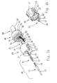
- a complete connector 1 according to the invention is shown in an exploded perspective view in FIG.
- the following parts are shown from bottom left to top right.
- a metallic plug-in part 2 which can be screwed onto a mating connector, is locked with an insulating carrier body 3, in which contact elements for signal transmission, not shown here, are held.
- the contact part 10 is particularly emphasized and shown, the insulation displacement terminal 19 of which, on the connection-side part 14, points into a corresponding, slot-shaped receptacle 21 of an insulating body 20. (See also FIG.
- the insulating body in which conductor guide channels 22 are also provided, in which signal-carrying electrical individual conductors 54 are guided, is followed by a pressure / clamping part 30 with which the electrical cable 50 is secured against being pulled out of the plug connector 1.
- a contact element 25 is inserted between the insulating body and the cable gland, which will be explained below.
- This is followed by a metallic screw sleeve 40 with which the plug connector is held together after being screwed onto the carrier housing 3 and a shielding sleeve 45 which, when appropriately positioned, forwards the electrical contact from the screw sleeve 40 via the insulating carrier body 3 to the metallic plug part 2.
- the contact part 10 already indicated in FIG. 1 is shown in FIG. 2a with its relevant individual parts.
- the contact part is formed from the two sections of a plug-side part 12 and a connection-side part 14, wherein the contact part can also be made in one piece.
- the plug-side part has a plug pin 15 for contacting a mating plug and a socket 16, into which a pin-shaped extension 17 of the connection-side part 14 can be inserted.
- the part 14 is held in the insulating body 20 by means of a locking spring 18.
- the second side of the connection-side part is designed as an insulation displacement connector 19, into which the contact element 25 is pressed with an angled portion 26 provided for this purpose.
- the contact element 25 is designed as a U-shaped flat bent part with an asymmetrically arranged round opening 29 in the central region 27, a bend 26 bent by 90 ° and a resilient end 28 bent over at least 35 ° to the central region.
- the contact element on the angled side 26 in the receptacle 21 ' is contacted with the insulation displacement connector 19 and, on the other side, is clamped in the axially arranged recess 23 in the insulating body 30 with the bent resilient end 28.
- Fig. 2b the insulating body 10 is rotated by about 180 ° and from the perspective of the pressure / clamping part 30 shown, so that the position of the contact element 25 on the surface of this side of the insulator is clarified again.
- the axially arranged, lateral recess 23 has a step-like structure and a projection 23 'is provided is around which the cable shield is to be led and over which the resilient end 28 of the contact part 25 engages in the recess 23.
- a collar 32 is formed on the side of the pressure / clamping part 30 facing the insulating body, which collar has raised polarizing means 34 which engage in corresponding recesses 24 in the insulating body 20. Furthermore, a further recess 36 is provided in the collar over the entire height of the collar, into which the contact element 25 extends with the bent, resilient end 28.
- the cable shield 52 is twisted before assembly of the connector and threaded through the opening 29 in the contact element.
- the individual conductors 54 are then inserted into the conductor guide channels 22 of the insulating part and the pressure / clamping part 30 with the contact element 25 is placed on the insulating body 20.
- the twisted cable shield is inserted into the recess 23 formed axially on the outer wall of the insulating body, the bent, resilient end 28 pressing the twisted cable shield into the recess.
- Single conductor ends 54 protruding beyond the insulating body and cable shielding are cut off and insulating bodies with cable glands are pushed into the carrier body 3.
- the individual conductors guided in the conductor guide channels are cut through the insulation displacement contacts (not shown here) which are firmly inserted in the carrier body and at the same time an electrically conductive connection to the contact part 10 is established.
- the screw sleeve 40 is then pushed on and screwed to the carrier body 3.
- the bent, resilient end 28 is inserted into a groove 5 provided for this purpose in the carrier body and pressed with the bending edge 28 'against the inner wall 42 of the external screw connection, so that in addition to an internal shield, a second electrically conductive outer shield is also provided via the screw sleeve 40.
- this shielding only becomes active when the sleeve 45 is pulled over the screw sleeve 40 and the plug-in part 2, so that the insulating part of the carrier body 3 is bridged, as shown in FIG. 3 for the connector 1 shown in its entirety.
- FIG. 4 shows in detail how the contact element 25 presses with its bending edge 28 ′ against the inner wall 42 of the metallic screw sleeve 40 in order to pass on the potential of the cable shield 52, which is guided through the opening 29 and at the resilient end 28 is applied.
- the insulation displacement contact 19 which is positioned in the receptacle 21, is contacted with the bend 26 which is inserted in the receptacle 21 '.
Landscapes
- Details Of Connecting Devices For Male And Female Coupling (AREA)
- Coupling Device And Connection With Printed Circuit (AREA)
Abstract
Description
So ist aus der DE 198 37 530 C1 eine Kabeleinführung bekannt bei der ein geschirmtes Kabel mittels eines elektrisch leitenden Gleitringes erfolgt, der mit einer elektrisch leitenden Druckschraube kontaktiert.
Dabei weist die eine Seite des Kontaktelementes zu einem im Isolierkörper integrierten Kontaktteil, während die andere Seite, mit einer Öffnung für das zu verdrillende Abschirmgeflecht des geschirmten elektrischen Kabels versehen ist sowie einem umgebogenen federnden Kontaktende, das das Abschirmgeflecht in einer im Isolierkörper vorgesehenen Ausnehmung festklemmt.
- Fig. 1
- einen Rundsteckverbinder in einer auseinandergezogenen Darstellung,
- Fig. 2a
- elektrische Verbindung des Innenleiters in einer auseinandergezogenen Darstellung,
- Fig. 2b
- einen Isolierkörper mit einem Kontaktelement um 180° gegenüber der Fig. 2a gedreht,
- Fig. 3
- eine isometrische Darstellung eines kompletten Rundsteckverbinders, und
- Fig. 4
- eine Detaildarstellung der Kontaktierung zwischen dem Kontaktelement und der Hülse.
Speziell herausgehoben und gezeigt ist das Kontaktteil 10, dessen Schneidklemme 19 am anschlussseitigen Teil 14 in eine entsprechende, schlitzförmige Aufnahme 21 eines Isolierkörpers 20 weist. (Siehe auch Fig. 2a) Auf den Isolierkörper, in dem auch Leiterführungskanäle 22 vorgesehen sind, in denen signalführende elektrische Einzelleiter 54 geführt sind, folgt ein Druck/Klemmteil 30, mit dem das elektrische Kabel 50 gegen Auszug aus dem Steckverbinder 1 gesichert ist.
Zwischen dem Isolierkörper und der Kabelverschraubung ist ein Kontaktelement 25 eingefügt, das weiter unten erklärt wird.
Darauf folgt eine metallische Schraubhülse 40 mit der der Steckverbinder nach dem Aufschrauben auf das Trägergehäuse 3 zusammengehalten wird sowie eine Schirmhülse 45, die bei entsprechender Positionierung den elektrischen Kontakt von der Schraubhülse 40 über den isolierenden Trägerkörper 3 zum metallischen Steckteil 2 weiterleitet.
Das steckseitige Teil weist einen Steckstift 15 zur Kontaktierung mit einem Gegenstecker und eine Buchse 16 auf, in die ein stiftförmiger Ansatz 17 des anschlussseitigen Teiles 14 einfügbar ist. Das Teil 14 wird mittels einer Arretierungsfeder 18 im Isolierkörper 20 festgehalten. Die zweite Seite des anschlussseitigen Teiles ist als Schneidklemme 19 ausgebildet, in die das Kontaktelement 25 mit einer dazu vorgesehenen Abwinklung 26 eingedrückt wird.
Das Kontaktelement 25 ist als U-förmiges flaches Biegeteil mit einer asymmetrisch angeordneten runden Öffnung 29 im mittleren Bereich 27, einer um 90° abgebogenen Abwinklung 26 und einem auf mindestens 35° zum mittleren Bereich umgebogenen federnden Ende 28 ausgebildet.
Bei der Montage wird das Kontaktelement auf der Abwinklungsseite 26 in der Aufnahme 21' mit der Schneidklemme 19 kontaktiert und auf der anderen Seite mit dem umgebogenen federnden Ende 28 in der axial angeordneten Ausnehmung 23 im Isolierkörper 30 eingeklemmt.
Weiterhin ist im Kragen eine weitere Ausnehmung 36 über die gesamte Höhe des Kragens vorgesehen, in die das Kontaktelement 25 mit dem umgebogenen, federnden Ende 28 hineinreicht.
Die Kabelschirmung 52 wird vor der Montage des Steckverbinders verdrillt und durch die Öffnung 29 im Kontaktelement gefädelt.
Anschließend werden die Einzelleiter 54 in die Leiterführungskanäle 22 des Isolierteiles eingeschoben und das Druck/Klemmteil 30 mit dem Kontaktelement 25 auf den Isolierkörper 20 aufgesetzt.
Dabei wird die verdrillte Kabelschirmung in die axial an der Außenwandung des Isolierkörpers eingeformte Ausnehmung 23 eingelegt, wobei das umgebogene, federnde Ende 28 die verdrillte Kabelschirmung in die Ausnehmung presst.
Über den Isolierkörper hinausragende Einzelleiterenden 54 sowie Kabelschirmung werden abgeschnitten und Isolierkörper mit Kabelverschraubung in den Trägerkörper 3 geschoben. Dabei werden die in den Leiterführungskanälen geführten Einzelleiter durch die im Trägerkörper fest eingefügten (hier nicht gezeigten) Schneidklemmkontakte geschnitten und gleichzeitig eine elektrisch leitende Verbindung zu dem Kontaktteil 10 hergestellt. Anschließend wird die Schraubhülse 40 aufgeschoben und mit dem Trägerkörper 3 verschraubt. Dabei wird das umgebogene, federnde Ende 28 in eine dafür vorgesehene Nut 5 im Trägerkörper eingefügt und mit der Biegekante 28' gegen die Innenwandung 42 der Außenverschraubung gedrückt, so dass neben einer innenliegenden Abschirmung hiermit auch eine zweite elektrisch leitende Außenabschirmung über die Schraubhülse 40 erfolgt. Diese Abschirmung wird jedoch erst aktiv, wenn die Hülse 45 über die Schraubhülse 40 und das Steckteil 2 gezogen wird, so dass der isolierende Teil des Trägerkörpers 3 überbrückt ist, wie in der Fig. 3 bei dem komplett dargestellten Steckverbinder 1 gezeigt.
Auf der anderen Seite des Kontaktelentes 25 wird mit der Abwinklung 26, die in der Aufnahme 21' eingefügt ist, die Schneidklemme 19 kontaktiert, die in der Aufnahme 21 positioniert ist.
Claims (5)
- Rundsteckverbinder für abgeschirmte elektrische Kabel (50) mit einem in einem Trägerkörper (3) angeordneten Isolierkörper (20) und einer Kabelverschraubung, bestehend aus einem Druck/Klemmteil (30) und einer metallischen Schraubhülse (40), wobei beim Aufschrauben der Schraubhülse auf den Trägerkörper, das Druck/Klemmteil gegen den Isolierkörper drückt, dadurch gekennzeichnet, dass zur Kontaktierung einer Kabelschirmung (52) des elektrischen Leiters (50) ein Kontaktelement (25) vorgesehen ist, wobei das Kontaktelement auf der zum Kabelanschluss weisenden Seite des Isolierkörpers (20) angeordnet ist,
dass das Kontaktelement (25) als flaches Biegeteil mit einem umgebogenen, federnden Ende (28) versehen ist das über einen Vorsprung (23') greift, der in einer axial in der Außenwandung des Isolierkörpers angeordnete Ausnehmung (23) vorgesehen ist,
dass das Kontaktelement (25) mit einer Öffnung (29) versehen ist, in die die Kabelschirmung (52) eingeführt ist, wobei die Kabelschirmung in der Ausnehmung (23) aufgenommen und mit dem umgebogenen federnden Ende (28) festgeklemmt ist, und
dass das Kontaktelement (25) mit dem umgebogenen, federnden Ende (28) so angeordnet ist, das beim Aufschrauben der Schraubhülse (40) die Biegekante (28') des federnden Endes gegen die Innenwand (42) der Schraubhülse drückt. - Steckverbinder nach Anspruch 1, dadurch gekennzeichnet, dass das Kontaktelement (25) dem federnden Ende (28) gegenüberliegend eine Abwinklung (26) aufweist, die in eine schlitzförmige Aufnahme (21') im Isolierkörper (20) eintaucht.
- Steckverbinder nach Anspruch 1 oder 2, dadurch gekennzeichnet dass in dem Schlitz (21) eine Schneidklemme (19) angeordnet ist, die mit der Abwinklung (26) des Kontaktelementes (25) kontaktiert.
- Steckverbinder nach einem der vorstehenden Ansprüche, dadurch gekennzeichnet, dass an dem Isolierkörper (20) und dem Druck/Klemmteil (30) miteinander wirkende Polarisationsmittel (24, 34) vorgesehen sind.
- Steckverbinder nach einem der vorstehenden Ansprüche, dadurch gekennzeichnet, dass der Isolierkörper (20) als Leiterführungsteil für elektrische Leiter (54) vorgesehen ist, die in entsprechend geformten Leiterführungskanälen (22) von Schneidklemmkontakten kontaktiert werden.
Applications Claiming Priority (2)
| Application Number | Priority Date | Filing Date | Title |
|---|---|---|---|
| DE10216483 | 2002-04-13 | ||
| DE10216483A DE10216483C1 (de) | 2002-04-13 | 2002-04-13 | Rundsteckverbinder für abgeschirmte elektrische Kabel |
Publications (2)
| Publication Number | Publication Date |
|---|---|
| EP1355386A1 true EP1355386A1 (de) | 2003-10-22 |
| EP1355386B1 EP1355386B1 (de) | 2010-07-28 |
Family
ID=28458808
Family Applications (1)
| Application Number | Title | Priority Date | Filing Date |
|---|---|---|---|
| EP03005857A Expired - Lifetime EP1355386B1 (de) | 2002-04-13 | 2003-03-15 | Rundsteckverbinder für abgeschirmte elektrische Kabel |
Country Status (4)
| Country | Link |
|---|---|
| US (1) | US6716041B2 (de) |
| EP (1) | EP1355386B1 (de) |
| JP (1) | JP3860557B2 (de) |
| DE (2) | DE10216483C1 (de) |
Cited By (2)
| Publication number | Priority date | Publication date | Assignee | Title |
|---|---|---|---|---|
| EP1538714A1 (de) | 2003-12-02 | 2005-06-08 | Harting Electric GmbH & Co. KG | Anordnung eines Kontaktelementes in einem Rundsteckverbinder |
| EP2608326A1 (de) * | 2011-12-20 | 2013-06-26 | Telegärtner Karl Gärtner Gmbh | Kabelverbindungsvorrichtung |
Families Citing this family (62)
| Publication number | Priority date | Publication date | Assignee | Title |
|---|---|---|---|---|
| US7515693B2 (en) | 2004-08-06 | 2009-04-07 | Powerphone, Inc. | Call handler systems and methods |
| JP4516819B2 (ja) * | 2004-10-20 | 2010-08-04 | 株式会社オーディオテクニカ | コンデンサマイクロホン |
| US8157589B2 (en) | 2004-11-24 | 2012-04-17 | John Mezzalingua Associates, Inc. | Connector having a conductively coated member and method of use thereof |
| US7114990B2 (en) | 2005-01-25 | 2006-10-03 | Corning Gilbert Incorporated | Coaxial cable connector with grounding member |
| US20070161299A1 (en) * | 2006-01-07 | 2007-07-12 | Kuo-Hsiung Chen | Structure for firmly combining cables with clamping element |
| DE202006011850U1 (de) * | 2006-08-02 | 2006-10-05 | Harting Electric Gmbh & Co. Kg | Kontaktelement für geschirmte Steckverbinder |
| TWI422105B (zh) * | 2008-06-13 | 2014-01-01 | Furutech Co Ltd | Power plug |
| US8075337B2 (en) | 2008-09-30 | 2011-12-13 | Belden Inc. | Cable connector |
| US8025518B2 (en) | 2009-02-24 | 2011-09-27 | Corning Gilbert Inc. | Coaxial connector with dual-grip nut |
| US7824216B2 (en) | 2009-04-02 | 2010-11-02 | John Mezzalingua Associates, Inc. | Coaxial cable continuity connector |
| US9017101B2 (en) | 2011-03-30 | 2015-04-28 | Ppc Broadband, Inc. | Continuity maintaining biasing member |
| US8573996B2 (en) | 2009-05-22 | 2013-11-05 | Ppc Broadband, Inc. | Coaxial cable connector having electrical continuity member |
| US8287320B2 (en) | 2009-05-22 | 2012-10-16 | John Mezzalingua Associates, Inc. | Coaxial cable connector having electrical continuity member |
| US8444445B2 (en) | 2009-05-22 | 2013-05-21 | Ppc Broadband, Inc. | Coaxial cable connector having electrical continuity member |
| US9570845B2 (en) | 2009-05-22 | 2017-02-14 | Ppc Broadband, Inc. | Connector having a continuity member operable in a radial direction |
| US8272893B2 (en) | 2009-11-16 | 2012-09-25 | Corning Gilbert Inc. | Integrally conductive and shielded coaxial cable connector |
| TWI549386B (zh) | 2010-04-13 | 2016-09-11 | 康寧吉伯特公司 | 具有防止進入及改良接地之同軸連接器 |
| DE102010017265B4 (de) * | 2010-06-07 | 2012-03-01 | Phoenix Contact Gmbh & Co. Kg | Kabelanschlusseinrichtung und Verfahren zum Anschließen eines Kabels an eine Kabelanschlusseinrichtung |
| US8888526B2 (en) | 2010-08-10 | 2014-11-18 | Corning Gilbert, Inc. | Coaxial cable connector with radio frequency interference and grounding shield |
| US8167636B1 (en) * | 2010-10-15 | 2012-05-01 | John Mezzalingua Associates, Inc. | Connector having a continuity member |
| US8323053B2 (en) | 2010-10-18 | 2012-12-04 | John Mezzalingua Associates, Inc. | Connector having a constant contact nut |
| US8167635B1 (en) | 2010-10-18 | 2012-05-01 | John Mezzalingua Associates, Inc. | Dielectric sealing member and method of use thereof |
| TWI558022B (zh) | 2010-10-27 | 2016-11-11 | 康寧吉伯特公司 | 具有耦合器和固持及釋放機制的推入固定式纜線連接器 |
| US8337229B2 (en) | 2010-11-11 | 2012-12-25 | John Mezzalingua Associates, Inc. | Connector having a nut-body continuity element and method of use thereof |
| US8414322B2 (en) | 2010-12-14 | 2013-04-09 | Ppc Broadband, Inc. | Push-on CATV port terminator |
| US8398421B2 (en) | 2011-02-01 | 2013-03-19 | John Mezzalingua Associates, Inc. | Connector having a dielectric seal and method of use thereof |
| US8157588B1 (en) | 2011-02-08 | 2012-04-17 | Belden Inc. | Cable connector with biasing element |
| US8465322B2 (en) | 2011-03-25 | 2013-06-18 | Ppc Broadband, Inc. | Coaxial cable connector |
| US8342879B2 (en) | 2011-03-25 | 2013-01-01 | John Mezzalingua Associates, Inc. | Coaxial cable connector |
| US8366481B2 (en) | 2011-03-30 | 2013-02-05 | John Mezzalingua Associates, Inc. | Continuity maintaining biasing member |
| US8388377B2 (en) | 2011-04-01 | 2013-03-05 | John Mezzalingua Associates, Inc. | Slide actuated coaxial cable connector |
| US8348697B2 (en) | 2011-04-22 | 2013-01-08 | John Mezzalingua Associates, Inc. | Coaxial cable connector having slotted post member |
| US9203167B2 (en) | 2011-05-26 | 2015-12-01 | Ppc Broadband, Inc. | Coaxial cable connector with conductive seal |
| US9711917B2 (en) | 2011-05-26 | 2017-07-18 | Ppc Broadband, Inc. | Band spring continuity member for coaxial cable connector |
| US8758050B2 (en) | 2011-06-10 | 2014-06-24 | Hiscock & Barclay LLP | Connector having a coupling member for locking onto a port and maintaining electrical continuity |
| US8591244B2 (en) | 2011-07-08 | 2013-11-26 | Ppc Broadband, Inc. | Cable connector |
| US9190744B2 (en) | 2011-09-14 | 2015-11-17 | Corning Optical Communications Rf Llc | Coaxial cable connector with radio frequency interference and grounding shield |
| US20130072057A1 (en) | 2011-09-15 | 2013-03-21 | Donald Andrew Burris | Coaxial cable connector with integral radio frequency interference and grounding shield |
| US9147955B2 (en) | 2011-11-02 | 2015-09-29 | Ppc Broadband, Inc. | Continuity providing port |
| US9136654B2 (en) | 2012-01-05 | 2015-09-15 | Corning Gilbert, Inc. | Quick mount connector for a coaxial cable |
| US9407016B2 (en) | 2012-02-22 | 2016-08-02 | Corning Optical Communications Rf Llc | Coaxial cable connector with integral continuity contacting portion |
| US9287659B2 (en) | 2012-10-16 | 2016-03-15 | Corning Optical Communications Rf Llc | Coaxial cable connector with integral RFI protection |
| US9147963B2 (en) * | 2012-11-29 | 2015-09-29 | Corning Gilbert Inc. | Hardline coaxial connector with a locking ferrule |
| US9153911B2 (en) | 2013-02-19 | 2015-10-06 | Corning Gilbert Inc. | Coaxial cable continuity connector |
| US9172154B2 (en) | 2013-03-15 | 2015-10-27 | Corning Gilbert Inc. | Coaxial cable connector with integral RFI protection |
| CN103199397A (zh) * | 2013-03-27 | 2013-07-10 | 江苏宏信电子科技有限公司 | 一种射频同轴连接器 |
| US9052469B2 (en) | 2013-04-26 | 2015-06-09 | Corning Cable Systems Llc | Preterminated fiber optic connector sub-assemblies, and related fiber optic connectors, cable assemblies, and methods |
| US10290958B2 (en) | 2013-04-29 | 2019-05-14 | Corning Optical Communications Rf Llc | Coaxial cable connector with integral RFI protection and biasing ring |
| EP3000154B1 (de) | 2013-05-20 | 2019-05-01 | Corning Optical Communications RF LLC | Koaxialkabelverbinder mit integralem rfi-schutz |
| US9548557B2 (en) | 2013-06-26 | 2017-01-17 | Corning Optical Communications LLC | Connector assemblies and methods of manufacture |
| US9048599B2 (en) | 2013-10-28 | 2015-06-02 | Corning Gilbert Inc. | Coaxial cable connector having a gripping member with a notch and disposed inside a shell |
| TWM482872U (zh) * | 2014-03-25 | 2014-07-21 | Amphenol Ltw Technology Co Ltd | 刺破型連接器接線結構 |
| DE102014109040B4 (de) * | 2014-06-27 | 2016-03-10 | Phoenix Contact Gmbh & Co. Kg | Kabelanschlussbauteil, Kabelanschlusseinrichtung, Kabelverbindungseinrichtung sowie Montageverfahren |
| WO2016073309A1 (en) | 2014-11-03 | 2016-05-12 | Corning Optical Communications Rf Llc | Coaxial cable connector with integral rfi protection |
| US10033122B2 (en) | 2015-02-20 | 2018-07-24 | Corning Optical Communications Rf Llc | Cable or conduit connector with jacket retention feature |
| US9590287B2 (en) | 2015-02-20 | 2017-03-07 | Corning Optical Communications Rf Llc | Surge protected coaxial termination |
| US10211547B2 (en) | 2015-09-03 | 2019-02-19 | Corning Optical Communications Rf Llc | Coaxial cable connector |
| CN108475881B (zh) | 2015-11-19 | 2020-10-20 | 康宁光电通信Rf有限责任公司 | 同轴电缆连接器 |
| US9525220B1 (en) | 2015-11-25 | 2016-12-20 | Corning Optical Communications LLC | Coaxial cable connector |
| CN108616015B (zh) * | 2016-12-12 | 2020-04-24 | 富士康(昆山)电脑接插件有限公司 | 电连接器及其组件 |
| CN110611291B (zh) * | 2018-09-30 | 2021-05-18 | 中航光电科技股份有限公司 | 接线器 |
| US12034264B2 (en) | 2021-03-31 | 2024-07-09 | Corning Optical Communications Rf Llc | Coaxial cable connector assemblies with outer conductor engagement features and methods for using the same |
Citations (3)
| Publication number | Priority date | Publication date | Assignee | Title |
|---|---|---|---|---|
| US3015794A (en) * | 1956-03-30 | 1962-01-02 | Bendix Corp | Electrical connector with grounding strip |
| EP0653804A1 (de) * | 1993-11-17 | 1995-05-17 | Thomas & Betts Corporation | Elektrischer Verbinder mit Leiterhalterung |
| DE19837530C1 (de) * | 1998-05-28 | 1999-12-30 | Harting Kgaa | Kabeleinführung |
Family Cites Families (4)
| Publication number | Priority date | Publication date | Assignee | Title |
|---|---|---|---|---|
| US5310359A (en) * | 1993-06-10 | 1994-05-10 | Molex Incorporated | Cable connector with strain relief |
| US6116955A (en) * | 1995-05-05 | 2000-09-12 | The Boeing Company | EMI terminating and grounding strain relief clamp assembly |
| DE29621436U1 (de) * | 1996-12-10 | 1997-02-27 | Chen, Michael Y., Taipei | Vollständig abgeschirmte elektrische Buchsenanordnung |
| JP3485150B2 (ja) * | 1997-07-02 | 2004-01-13 | 矢崎総業株式会社 | シールドコネクタ |
-
2002
- 2002-04-13 DE DE10216483A patent/DE10216483C1/de not_active Expired - Fee Related
-
2003
- 2003-03-15 EP EP03005857A patent/EP1355386B1/de not_active Expired - Lifetime
- 2003-03-15 DE DE50312922T patent/DE50312922D1/de not_active Expired - Lifetime
- 2003-04-10 JP JP2003106960A patent/JP3860557B2/ja not_active Expired - Fee Related
- 2003-04-10 US US10/410,995 patent/US6716041B2/en not_active Expired - Lifetime
Patent Citations (3)
| Publication number | Priority date | Publication date | Assignee | Title |
|---|---|---|---|---|
| US3015794A (en) * | 1956-03-30 | 1962-01-02 | Bendix Corp | Electrical connector with grounding strip |
| EP0653804A1 (de) * | 1993-11-17 | 1995-05-17 | Thomas & Betts Corporation | Elektrischer Verbinder mit Leiterhalterung |
| DE19837530C1 (de) * | 1998-05-28 | 1999-12-30 | Harting Kgaa | Kabeleinführung |
Cited By (2)
| Publication number | Priority date | Publication date | Assignee | Title |
|---|---|---|---|---|
| EP1538714A1 (de) | 2003-12-02 | 2005-06-08 | Harting Electric GmbH & Co. KG | Anordnung eines Kontaktelementes in einem Rundsteckverbinder |
| EP2608326A1 (de) * | 2011-12-20 | 2013-06-26 | Telegärtner Karl Gärtner Gmbh | Kabelverbindungsvorrichtung |
Also Published As
| Publication number | Publication date |
|---|---|
| EP1355386B1 (de) | 2010-07-28 |
| JP3860557B2 (ja) | 2006-12-20 |
| US6716041B2 (en) | 2004-04-06 |
| JP2003317875A (ja) | 2003-11-07 |
| DE10216483C1 (de) | 2003-11-20 |
| DE50312922D1 (de) | 2010-09-09 |
| US20030194890A1 (en) | 2003-10-16 |
Similar Documents
| Publication | Publication Date | Title |
|---|---|---|
| EP1355386B1 (de) | Rundsteckverbinder für abgeschirmte elektrische Kabel | |
| DE102009021594B4 (de) | Elektrischer Steckverbinder und elektrische Steckverbindung sowie Verfahren zum Anschließen der Andern eines mehradrigen Kabels an einen elektrischen Steckverbinder | |
| EP1239550B1 (de) | Steckverbinder | |
| EP1926179B1 (de) | Steckverbinder für konfektionierte elektrische Leiter | |
| EP2797175B1 (de) | Stecker für ein mehrere Adern aufweisendes Daten- und/oder Telekommunikations-Kabel | |
| EP3959781B1 (de) | Steckverbinder und steckverbinderanornung | |
| DE102014109040B4 (de) | Kabelanschlussbauteil, Kabelanschlusseinrichtung, Kabelverbindungseinrichtung sowie Montageverfahren | |
| EP2842197B1 (de) | Isolierkörper eines steckverbinders | |
| AT504850B1 (de) | Elektrisches kabel mit an beiden kabelenden montierten kabelsteckverbindern | |
| EP3116074A1 (de) | Steckbuchsenmodul | |
| DE202008004892U1 (de) | Schirmübergabeelement für Steckverbinder | |
| DE102012105257B4 (de) | Isolierkörper eines Steckverbinders | |
| EP2417675B1 (de) | Steckersystemgehäuse für mehradrige kabel | |
| EP1467441A2 (de) | Schnellanschliessbare Steckverbindung in Spannzangentechnik | |
| DE102017222809B4 (de) | Elektrischer Steckverbinder und Steckverbindung | |
| DE19751786A1 (de) | Rundsteckverbinder für ein geschirmtes Kabel | |
| DE102017126185B4 (de) | Elektrisches Kontaktelement | |
| EP2071676A2 (de) | Steckeranordnung | |
| EP3676918A1 (de) | Gewinkelter steckverbinder und verfahren zur konfektionierung | |
| DE10323616A1 (de) | Schnellanschließbare Steckverbindung in Spannzangentechnik | |
| DE202007011829U1 (de) | Kontaktelement | |
| DE202017107625U1 (de) | Elektrischer Steckverbinder | |
| DE202012101303U1 (de) | Steckverbindergehäuse | |
| DE19627971C2 (de) | BNC-Stecker | |
| DE19803677B4 (de) | Elektrisches Steckverbindergehäuse |
Legal Events
| Date | Code | Title | Description |
|---|---|---|---|
| PUAI | Public reference made under article 153(3) epc to a published international application that has entered the european phase |
Free format text: ORIGINAL CODE: 0009012 |
|
| AK | Designated contracting states |
Kind code of ref document: A1 Designated state(s): AT BE BG CH CY CZ DE DK EE ES FI FR GB GR HU IE IT LI LU MC NL PT SE SI SK TR |
|
| AX | Request for extension of the european patent |
Extension state: AL LT LV MK RO |
|
| 17P | Request for examination filed |
Effective date: 20040213 |
|
| AKX | Designation fees paid |
Designated state(s): CH DE ES FR GB IT LI |
|
| GRAP | Despatch of communication of intention to grant a patent |
Free format text: ORIGINAL CODE: EPIDOSNIGR1 |
|
| GRAS | Grant fee paid |
Free format text: ORIGINAL CODE: EPIDOSNIGR3 |
|
| GRAA | (expected) grant |
Free format text: ORIGINAL CODE: 0009210 |
|
| AK | Designated contracting states |
Kind code of ref document: B1 Designated state(s): CH DE ES FR GB IT LI |
|
| REG | Reference to a national code |
Ref country code: GB Ref legal event code: FG4D Free format text: NOT ENGLISH |
|
| REG | Reference to a national code |
Ref country code: CH Ref legal event code: EP |
|
| REF | Corresponds to: |
Ref document number: 50312922 Country of ref document: DE Date of ref document: 20100909 Kind code of ref document: P |
|
| PG25 | Lapsed in a contracting state [announced via postgrant information from national office to epo] |
Ref country code: IT Free format text: LAPSE BECAUSE OF FAILURE TO SUBMIT A TRANSLATION OF THE DESCRIPTION OR TO PAY THE FEE WITHIN THE PRESCRIBED TIME-LIMIT Effective date: 20100728 |
|
| PLBE | No opposition filed within time limit |
Free format text: ORIGINAL CODE: 0009261 |
|
| STAA | Information on the status of an ep patent application or granted ep patent |
Free format text: STATUS: NO OPPOSITION FILED WITHIN TIME LIMIT |
|
| PG25 | Lapsed in a contracting state [announced via postgrant information from national office to epo] |
Ref country code: ES Free format text: LAPSE BECAUSE OF FAILURE TO SUBMIT A TRANSLATION OF THE DESCRIPTION OR TO PAY THE FEE WITHIN THE PRESCRIBED TIME-LIMIT Effective date: 20101108 |
|
| 26N | No opposition filed |
Effective date: 20110429 |
|
| REG | Reference to a national code |
Ref country code: DE Ref legal event code: R097 Ref document number: 50312922 Country of ref document: DE Effective date: 20110429 |
|
| PGFP | Annual fee paid to national office [announced via postgrant information from national office to epo] |
Ref country code: GB Payment date: 20120327 Year of fee payment: 10 |
|
| PGFP | Annual fee paid to national office [announced via postgrant information from national office to epo] |
Ref country code: CH Payment date: 20120425 Year of fee payment: 10 |
|
| REG | Reference to a national code |
Ref country code: CH Ref legal event code: PL |
|
| GBPC | Gb: european patent ceased through non-payment of renewal fee |
Effective date: 20130315 |
|
| PG25 | Lapsed in a contracting state [announced via postgrant information from national office to epo] |
Ref country code: CH Free format text: LAPSE BECAUSE OF NON-PAYMENT OF DUE FEES Effective date: 20130331 Ref country code: GB Free format text: LAPSE BECAUSE OF NON-PAYMENT OF DUE FEES Effective date: 20130315 Ref country code: LI Free format text: LAPSE BECAUSE OF NON-PAYMENT OF DUE FEES Effective date: 20130331 |
|
| REG | Reference to a national code |
Ref country code: FR Ref legal event code: PLFP Year of fee payment: 14 |
|
| REG | Reference to a national code |
Ref country code: FR Ref legal event code: PLFP Year of fee payment: 15 |
|
| PGFP | Annual fee paid to national office [announced via postgrant information from national office to epo] |
Ref country code: DE Payment date: 20170307 Year of fee payment: 15 Ref country code: FR Payment date: 20170213 Year of fee payment: 15 |
|
| REG | Reference to a national code |
Ref country code: DE Ref legal event code: R119 Ref document number: 50312922 Country of ref document: DE |
|
| PG25 | Lapsed in a contracting state [announced via postgrant information from national office to epo] |
Ref country code: DE Free format text: LAPSE BECAUSE OF NON-PAYMENT OF DUE FEES Effective date: 20181002 |
|
| PG25 | Lapsed in a contracting state [announced via postgrant information from national office to epo] |
Ref country code: FR Free format text: LAPSE BECAUSE OF NON-PAYMENT OF DUE FEES Effective date: 20180331 |