EP1355121A1 - Mörsergranate - Google Patents
Mörsergranate Download PDFInfo
- Publication number
- EP1355121A1 EP1355121A1 EP03005297A EP03005297A EP1355121A1 EP 1355121 A1 EP1355121 A1 EP 1355121A1 EP 03005297 A EP03005297 A EP 03005297A EP 03005297 A EP03005297 A EP 03005297A EP 1355121 A1 EP1355121 A1 EP 1355121A1
- Authority
- EP
- European Patent Office
- Prior art keywords
- grenade
- mortar
- rocket
- speed
- mortar grenade
- Prior art date
- Legal status (The legal status is an assumption and is not a legal conclusion. Google has not performed a legal analysis and makes no representation as to the accuracy of the status listed.)
- Withdrawn
Links
- 239000004570 mortar (masonry) Substances 0.000 title claims description 50
- 239000003380 propellant Substances 0.000 claims abstract description 26
- 238000002485 combustion reaction Methods 0.000 claims abstract description 5
- 230000007935 neutral effect Effects 0.000 abstract description 2
- 239000007789 gas Substances 0.000 description 7
- 239000002360 explosive Substances 0.000 description 3
- 230000001133 acceleration Effects 0.000 description 2
- 238000010304 firing Methods 0.000 description 2
- 230000000694 effects Effects 0.000 description 1
- 238000011156 evaluation Methods 0.000 description 1
- 230000024703 flight behavior Effects 0.000 description 1
- 239000002223 garnet Substances 0.000 description 1
- 238000012423 maintenance Methods 0.000 description 1
- 238000004519 manufacturing process Methods 0.000 description 1
- 238000005259 measurement Methods 0.000 description 1
Images

Classifications
-
- F—MECHANICAL ENGINEERING; LIGHTING; HEATING; WEAPONS; BLASTING
- F42—AMMUNITION; BLASTING
- F42B—EXPLOSIVE CHARGES, e.g. FOR BLASTING, FIREWORKS, AMMUNITION
- F42B30/00—Projectiles or missiles, not otherwise provided for, characterised by the ammunition class or type, e.g. by the launching apparatus or weapon used
- F42B30/08—Ordnance projectiles or missiles, e.g. shells
- F42B30/10—Mortar projectiles
- F42B30/12—Mortar projectiles with provision for additional propulsive charges, or for varying the length
Definitions
- the invention relates to a mortar grenade with a grenade body and one on the rear side tail unit connected to the shell.
- a pyrotechnic propellant charge is generally used as the drive in the form of e.g. Discs used at the rear end of the mortar shell, e.g. around the tail unit.
- Discs used at the rear end of the mortar shell, e.g. around the tail unit.
- a reduction in recoil forces could be done on the weapon side through a pipe return system and / or by extending the barrel, but lead such measures, among other things, to increase the manufacturing and maintenance costs and to limit the manageability of the grenade launcher.
- the invention has for its object the firing by the recoil forces total mortar shell load on weapon and weapon carrier for one Reduce the specified range of the grenade compared to existing systems or to significantly increase the range of the mortar projectiles with the same system load.
- the invention is essentially based on the idea of driving the mortar shell not a conventional pyrotechnic propellant charge, but to use a rocket engine, whose propellant charge is selected such that it is only a soft ejection of the Mortar grenade from the weapon barrel. After leaving the gun barrel you can the mortar grenade either by the same rocket engine or an additional one Rocket propulsion to be accelerated to a predetermined target speed.
- the target speed is determined, for example, by means of a mortar on the mortar arranged sensor, which is followed by an electronic evaluation unit, which the measured speed with a predetermined before the firing of the grenade Compare setpoint.
- the force is neutral Burn-up of the remaining propellant, i.e. the further burn-up of the propellant has an effect no longer (or no longer significantly) the further flight behavior of the grenade.
- Such a force-neutral burn-up can be achieved, for example, in that the propellant gases no longer generated by the rocket propellant through the rear outflow nozzles, but escape through openings arranged radially on the grenade.
- the propellant gases no longer generated by the rocket propellant through the rear outflow nozzles, but escape through openings arranged radially on the grenade.
- the electronic control device controllable valves are located in the corresponding gas lines with the electronic control device controllable valves.
- a satellite-based GPS navigation system intial measurement unit (IMV system)
- IMV system intial measurement unit
- pitot system a satellite-based GPS navigation system
- IMV system intial measurement unit
- pitot system a conventional pitot system
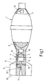
- 1 denotes a mortar grenade that is filled with an explosive 2 Grenade body 3 and a tail unit adjoining the rear of the grenade body 3 4 with tail 5 comprises.
- a rocket drive 6 is arranged, one with a rocket propellant 7 filled recess 8, a combustion chamber 9 and one up to the rear end 10 of the tail shaft 4 extending outflow nozzle 11 comprises.
- the outflow nozzle 11 can be closed by a controllable valve 12. Also are connected to the outflow nozzle 11 a plurality of radially outwardly directed gas lines 13, which can also be closed and opened by means of controllable valves 14.
- the mortar grenade 1 has one connected to an electronic control device 15 GPS sensor 16 for determining the speed of the mortar grenade 1 during its Flight on.
- the electronic control device 15 is via electrical lines 17 connected to the valves 12, 14.
- a target speed value is programmed into a memory of the control device 15. Then the rocket propellant 7 of the rocket drive 6 ignited by a detonator, not shown.
- the rocket propellant 7 is such designed that the mortar grenade after soft ejection at least the desired Speed reached after the rocket propellant 7 burned down.
- Control device 15 constantly by evaluating the GPS sensor 16 measured position data the flight speed of the grenade 1 and compares it with the specified target speed.
- FIG. 2 shows a further exemplary embodiment of a mortar grenade 1 'according to the invention shown. It is an intelligently controllable mortar projectile, which has both fold-out tail fins 5 'and fold-out control wings 19.
- the control device 15 ' is arranged on the bow side in the mortar grenade 1' and via a electrical line 20 with a GPS sensor 16 'and via electrical lines 17' with controllable valves 12 ', 14' connected.
- FIG. 1 contains the mortar grenade 1 'a chamber filled with explosives 2' as well as a rocket engine 6 '.
- the latter comprises a rocket propellant 7 'and a combustion chamber 9' with an adjoining outflow nozzle 11 '.
- a second can be found on the rear of the mortar grenade Rocket drive (booster) may be arranged, the propellant is selected such that it only to gently eject the grenade from the tube of the grenade launcher.
- the propellant is selected such that it only to gently eject the grenade from the tube of the grenade launcher.
- FIG.3 A corresponding embodiment is shown in Fig.3. Only the rear area of the mortar shell marked 1 ". In the tail unit this grenade 1 "is both a foldable tail unit 5" and a first rocket drive 6 "is provided.
- the second rocket drive is identified by the reference numerals 21 and its propellant is provided with the reference number 22.
- the first rocket drive 6 "integrated in the tail unit takes over the further acceleration the grenade 1 "until the predetermined one and in a memory of an electronic Control device stored target speed of the grenade 1 "is reached.
- the thrust jet can then turn to radially arranged openings of the Grenade 1 "are deflected, which are not shown in Figure 3 for reasons of better clarity are shown.
Landscapes
- Engineering & Computer Science (AREA)
- Chemical & Material Sciences (AREA)
- Combustion & Propulsion (AREA)
- General Engineering & Computer Science (AREA)
- Aiming, Guidance, Guns With A Light Source, Armor, Camouflage, And Targets (AREA)
Abstract
Description
- 1,1',1"
- Mörsergranate, Granate
- 2,2'
- Sprengstoff
- 3
- Granatkörper
- 4
- Leitwerkschaft
- 5,5',5"
- Leitwerk
- 6,6',6"
- Raketenantrieb, erster Raketenantrieb
- 7,7'
- Raketentreibsatz
- 8
- Ausnehmung
- 9,9'
- Brennkammer
- 10
- Ende
- 11,11'
- Ausströmdüse
- 12,12'
- Ventil
- 13
- Gasleitung, Mittel
- 14,14'
- Ventil
- 15,15'
- Steuervorrichtung
- 16,16'
- GPS-Sensor, Sensor
- 17,17'
- elektrische Leitung
- 19
- Steuerflügel
- 20
- elektrische Leitung
- 21
- zweiter Raketenantrieb, Booster
- 22
- Treibsatz
Claims (5)
- Mörsergranate mit einem Granatkörper (3) und einem sich heckseitig an den Granatkörper (3) anschließenden Leitwerkschaft (4) mit den Merkmalen:a) in dem Leitwerkschaft (4) der Mörsergranate (1; 1'; 1") ist ein erster Raketenantrieb (6; 6'; 6") angeordnet, der eine mit einem Raketentreibsatz (7; 7') mindestens teilweise gefüllte Ausnehmung (8), eine Brennkammer (9; 9') und eine sich bis zum heckseitigen Ende (10) des Leitwerkschaftes (4) erstreckende Ausströmdüse (11; 11') umfaßt;b) die Mörsergranate (1; 1'; 1") weist einen Sensor (16; 16') zur Ermittlung der Geschwindigkeit der Mörsergranate (1; 1'; 1") während ihres Fluges sowie eine elektronische Steuervorrichtung (15; 15') auf, die nach Erreichen einer vorgegebenen Sollgeschwindigkeit Mittel (13) einschaltet, welche einen kraftneutralen Abbrand des Raketentreibsatzes (7; 7') bewirken.
- Mörsergranate nach Anspruch 1, dadurch gekennzeichnet, daß der Raketentreibsatz (7) des ersten Raketenantriebes (6; 6'; 6") derart gewählt ist, daß er ein weiches Ausstoßen der Mörsergranate (1; 1'; 1") aus einem entsprechenden Waffenrohr bewirkt und anschließend die Mörsergranate (1; 1';1") bis zu einer vorgegebenen Geschwindigkeit beschleunigt.
- Mörsergranate nach Anspruch 1, dadurch gekennzeichnet, daß heckseitig an dem Leitwerkschaft der Mörsergranate (1") ein zweiter Raketenantrieb (21) lösbar angeordnet ist, welcher derart gewählt ist, daß er ein weiches Ausstoßen der Mörsergranate (1") aus einem entsprechenden Waffenrohr bewirkt und daß der erste Raketenantrieb (6") derart gewählt ist, daß er nach dem Auswerfen der Mörsergranate (1") diese auf ihre Sollgeschwindigkeit beschleunigt.
- Mörsergranate nach einem der Ansprüche 1 bis 3, dadurch gekennzeichnet, daß die Ausströmdüse (11; 11') mit radial nach außen geführten Gasleitungen (13) verbunden ist, und daß in den Gasleitungen (13) und in der Ausströmdüse (11; 11') von der elektronischen Steuervorrichtung (15; 15') ansteuerbare Ventile (12, 14; 12', 14') angeordnet sind, die von der Steuervorrichtung (15; 15') derart angesteuert werden, daß nach Erreichen der vorgegebenen Sollgeschwindigkeit der Schubstrahl des ersten Raketenantriebes (6; 6'; 6") nur noch durch die radialen Gasleitungen (13) nach außen gelangt.
- Mörsergranate nach einem der Ansprüche 1 bis 4, dadurch gekennzeichnet, daß es sich bei dem Sensor (16; 16') zur Ermittlung der Geschwindigkeit der Mörsergranate (1; 1'; 1") um ein Satelliten-Navigationssystem (GPS, IMV) handelt, welches aus den Positionsbestimmungen der Mörsergranate (1; 1'; 1") zu zwei unterschiedlichen Zeitpunkten eine Geschwindigkeitsermittlung vornimmt.
Applications Claiming Priority (4)
| Application Number | Priority Date | Filing Date | Title |
|---|---|---|---|
| DE10217169 | 2002-04-18 | ||
| DE10217169 | 2002-04-18 | ||
| DE10226515 | 2002-06-14 | ||
| DE10226515A DE10226515B3 (de) | 2002-04-18 | 2002-06-14 | Mörsergranate |
Publications (1)
| Publication Number | Publication Date |
|---|---|
| EP1355121A1 true EP1355121A1 (de) | 2003-10-22 |
Family
ID=28676063
Family Applications (1)
| Application Number | Title | Priority Date | Filing Date |
|---|---|---|---|
| EP03005297A Withdrawn EP1355121A1 (de) | 2002-04-18 | 2003-03-11 | Mörsergranate |
Country Status (2)
| Country | Link |
|---|---|
| EP (1) | EP1355121A1 (de) |
| IL (1) | IL155451A0 (de) |
Citations (5)
| Publication number | Priority date | Publication date | Assignee | Title |
|---|---|---|---|---|
| US1994490A (en) * | 1934-09-11 | 1935-03-19 | Leslie A Skinner | Rocket projectile |
| FR1363344A (fr) * | 1963-04-30 | 1964-06-12 | Soc Tech De Rech Ind | Roquette à propulsion différée |
| US3306205A (en) * | 1965-03-25 | 1967-02-28 | Marcus Irwin | Fin stabilized projectile |
| US3434291A (en) * | 1967-04-04 | 1969-03-25 | Thiokol Chemical Corp | Thrust termination apparatus for solid propellant rocket motors |
| US3705550A (en) * | 1970-11-02 | 1972-12-12 | Us Army | Solid rocket thrust termination device |
-
2003
- 2003-03-11 EP EP03005297A patent/EP1355121A1/de not_active Withdrawn
- 2003-04-15 IL IL15545103A patent/IL155451A0/xx unknown
Patent Citations (5)
| Publication number | Priority date | Publication date | Assignee | Title |
|---|---|---|---|---|
| US1994490A (en) * | 1934-09-11 | 1935-03-19 | Leslie A Skinner | Rocket projectile |
| FR1363344A (fr) * | 1963-04-30 | 1964-06-12 | Soc Tech De Rech Ind | Roquette à propulsion différée |
| US3306205A (en) * | 1965-03-25 | 1967-02-28 | Marcus Irwin | Fin stabilized projectile |
| US3434291A (en) * | 1967-04-04 | 1969-03-25 | Thiokol Chemical Corp | Thrust termination apparatus for solid propellant rocket motors |
| US3705550A (en) * | 1970-11-02 | 1972-12-12 | Us Army | Solid rocket thrust termination device |
Also Published As
| Publication number | Publication date |
|---|---|
| IL155451A0 (en) | 2003-11-23 |
Similar Documents
| Publication | Publication Date | Title |
|---|---|---|
| DE69811170T2 (de) | Grosskalibriges und weitreichendes Artilleriegeschoss | |
| DE69606950T2 (de) | Aerodynamisch stabilisiertes projektilsystem zur anwendung gegen unterwasserobjekte | |
| EP0764826B1 (de) | Trägergeschoss, das ein einziges Penetratorgeschoss trägt | |
| DE10212653B4 (de) | Lenkwaffen-Startvorrichtung und Verfahren zum Starten von Lenkwaffen | |
| DE2804270C2 (de) | Vorrichtung zur Bodensogreduzierung an einem Artilleriegeschoß | |
| DE3048617A1 (de) | Gefechtskopf mit sekundaerkoerpern als nutzlast | |
| DE3416787A1 (de) | Panzerbrechendes geschoss | |
| DE69422805T2 (de) | Flugbahnumlenkungsvorrichtung und verfahren für einen gefechtskopf | |
| EP0918209B1 (de) | Geschoss mit programmierbarem Zeitzünder | |
| DE3918005C2 (de) | ||
| EP0151676B1 (de) | Geschoss mit einem Nutzlastteil und einem Antriebsteil | |
| DE1283120B (de) | Schiessvorrichtung | |
| DE2830859A1 (de) | Boden-boden panzerabwehrwaffe | |
| DE2518593A1 (de) | Geschoss | |
| EP3014213B1 (de) | Zünder für eine mörsergranate und aus einem zapfenmörser verschiessbare mörsergranate mit einem derartigen zünder | |
| DE69422617T2 (de) | Verfahren und vorrichtung zur übertragung von einem gewünschten bewegungsmuster an einem fliegenden gefechtskopf | |
| DE102004002471B4 (de) | Vorrichtung und Verfahren zur Abgabe einer Antriebsenergie | |
| DE69411529T2 (de) | Treibkäfig für unterkalibergeschosse mit kontrollierter trennung der teile | |
| DE10226515B3 (de) | Mörsergranate | |
| DE1428637C1 (de) | Rohrfoermige Abschusseinrichtung fuer Geschosse,insbesondere fuer Flugkoerper | |
| DE68923769T2 (de) | Anzünder. | |
| DE69907791T2 (de) | Bausatz zum Umrüsten eines Sprenggeschosses auf ein Bentonstrukturen brechendes Geschoss, sowie ein derart umgerüstetes Geschoss | |
| DE19944379A1 (de) | Patrone | |
| WO2009046798A1 (de) | Verfahren zum verbringen von sonarbojen in ein zielgebiet und flugkörper zur durchführung dieses verfahrens | |
| EP3800436B1 (de) | Geschoss mit verkürzter reichweite |
Legal Events
| Date | Code | Title | Description |
|---|---|---|---|
| PUAI | Public reference made under article 153(3) epc to a published international application that has entered the european phase |
Free format text: ORIGINAL CODE: 0009012 |
|
| 17P | Request for examination filed |
Effective date: 20030724 |
|
| AK | Designated contracting states |
Kind code of ref document: A1 Designated state(s): AT BE BG CH CY CZ DE DK EE ES FI FR GB GR HU IE IT LI LU MC NL PT RO SE SI SK TR |
|
| AX | Request for extension of the european patent |
Extension state: AL LT LV MK |
|
| AKX | Designation fees paid |
Designated state(s): AT BE BG CH CY CZ DE DK EE ES FI FR GB GR HU IE IT LI LU MC NL PT RO SE SI SK TR |
|
| RAP1 | Party data changed (applicant data changed or rights of an application transferred) |
Owner name: RHEINMETALL WAFFE MUNITION GMBH |
|
| GRAP | Despatch of communication of intention to grant a patent |
Free format text: ORIGINAL CODE: EPIDOSNIGR1 |
|
| RBV | Designated contracting states (corrected) |
Designated state(s): AT BE BG CH CY CZ DK EE ES FI FR GB GR HU IE IT LI LU MC NL PT RO SE SI SK TR |
|
| REG | Reference to a national code |
Ref country code: DE Ref legal event code: 8566 |
|
| STAA | Information on the status of an ep patent application or granted ep patent |
Free format text: STATUS: THE APPLICATION IS DEEMED TO BE WITHDRAWN |
|
| 18D | Application deemed to be withdrawn |
Effective date: 20070530 |