Technical Field
The present invention relates to a hydrogen
purification apparatus of purifying a reformed gas
containing hydrogen as a main component and containing
carbon monoxide (hereinafter referred to as CO) to provide
high-purity hydrogen gas. Also, the present invention
relates to a hydrogen feeder for a polymer electrolyte
fuel cell or the like using hydrogen as a fuel.
Background Art
The fuel cell cogeneration system of high power
generation efficiency and high overall efficiency is
given attention as a distributed power plant using energy
effectively.
Many of fuel cells, for example, commercially
practical phosphoric fuel cells and polymer electrolyte
fuel cells being under development generate power using
hydrogen as a fuel. However, hydrogen is not secured as
an infrastructure, and thus needs to be produced at a
site where the system is placed.
One method of producing hydrogen is a steam reforming
method. A reformed gas obtained by mixing a raw material
such as a hydrocarbon based material such as natural gas,
LPG, naphtha, gasoline or kerosene, an alcohol based
material such as methanol, and ether with water, and by
subjecting the mixture to a steam reforming reaction in
a reforming unit provided with a reforming catalyst is
used as a hydrogen source such as in a fuel cell. In the
case of the polymer electrolyte fuel cell operating at
a low temperature of 100°C or lower, however, the Pt
catalyst for use in the electrode of the fuel cell may
be rendered poisonous by CO contained in the reformed
gas. If the Pt catalyst is rendered poisonous, the
reaction of hydrogen is hindered, and thus power
generation efficiency of the fuel cell is significantly
reduced. For this reason, CO should be removed to reduce
the concentration of CO to 100 ppm or smaller, preferably
10 ppm or smaller, using the hydrogen purification
apparatus.
In this steam reforming reaction, carbon monoxide
is produced as a by-product, but because the carbon
monoxide deteriorates the fuel cell electrode catalyst,
the carbon monoxide should be removed to reduce its
concentration to 100 ppm or smaller, preferably 10 ppm
or smaller especially for the polymer electrolyte fuel
cell.
Usually, for removing CO, CO and steam are made to
undergo a shift reaction to convert them into carbon
dioxide and hydrogen in a CO shifting unit with a CO
shifting catalyst body placed after the reforming unit
in the hydrogen purification apparatus, thereby reducing
the concentration of CO to the level of several thousand
ppm to 1% by volume.
Thereafter, oxygen is added thereto using a very small
amount of air, and CO is removed by a CO selection oxide
catalyst body to reduce the concentration of CO to the
level of several ppm at which the fuel cell is no longer
adversely affected. Here, the amount of oxygen to be added
should be one to three times as much as the CO concentration
for sufficiently removing CO, but at this time, hydrogen
is also consumed in response to the amount of oxygen to
be added. If the concentration of CO at the outlet of
the shifting unit is high, the amount of oxygen to be
added is also increased, and the amount of consumed
hydrogen is increased, thus significantly reducing
efficiency of the overall apparatus.
Therefore, it is necessary to reduce CO sufficiently
in the CO shifting unit with the CO shifting catalyst
body placed therein.
Traditionally, for the CO shifting catalyst,
copper-zinc based catalysts, copper-chrome based
catalysts and the like capable of being used at 150 to
300°C are used as low temperature CO shifting catalysts,
and iron-chrome based catalysts and the like functioning
at 300°C or higher are used as high temperature CO shifting
catalysts. For these CO shifting catalysts, only the low
temperature CO shifting catalyst was used, or the high
temperature CO shifting catalyst and low temperature CO
shifting catalyst were used in combination depending on
the uses of chemical plants and hydrogen generators for
fuel cells.
However, when the copper based low temperature CO
shifting catalyst is used as a main catalyst, a very high
catalytic activity is obtained, but the catalyst needs
to be activated by carrying out reduction treatment before
it is used. Further, because the catalyst generates heat
during the activation treatment, it was required to treat
the catalyst for a long time while adjusting the amount
of supplied reducing gas, for example, in order to prevent
the situation in which the temperature of the catalyst
is increased to above its heat-resistant temperature.
Also, because the once activated CO shifting catalyst
may be reoxidized and deteriorated if oxygen is entrained
at the time when the apparatus is stopped and so on, it
required some measures for prevention of oxidation and
so on. In addition, the low temperature CO shifting
catalyst has poor heat resistance, and thus cannot be
heated rapidly at the time of starting the apparatus,
and therefore it required some measures of increasing
temperature slowly and so on.
On the other hand, in the case where only the high
temperature CO shifting catalyst is used, the situation
in which the temperature rises to somewhat excessive level
can be accepted because of high heat resistance, and
therefore heating during startup or the like is easier.
However, the CO shift reaction is an equilibrium
reaction that hardly proceeds toward reduction in CO
concentration in the high temperature region, and it was
difficult to reduce the CO concentration to 1% by volume
or smaller when a high temperature CO shifting catalyst
functioning only at high temperature was used. Therefore,
there were cases where purification efficiency in a CO
purification unit connected subsequently was reduced.
In this way, in conventional techniques, there have
been problems in which they cannot be applied well to
the application where the hydrogen purification apparatus
is frequently started and stopped because it takes much
time to start the apparatus, and because of complicated
handling.
Also, as described in Japanese Patent Laid-Open No.
2000-178007, use of precious metal based catalysts not
requiring reduction treatments has been proposed. The
precious based catalyst is used at about 250 to 350°C,
but in the high temperature region, not only carbon
monoxide is reduced by the shift reaction, but also a
reaction tends to occur in which carbon monoxide and
hydrogen in the reformed gas is reacted with each other
to produce methane as a by-product, and thus there have
been cases where the efficiency of the apparatus is
reduced.
Disclosure of the Invention
In view of the above problems of conventional
techniques, the present invention has as its object
provision of a hydrogen purification apparatus enabling
heating during startup and the like to be carried out
smoothly, and having high CO purification efficiency,
for example.
Also, in view of the problems of conventional
techniques, the present invention has as its object
provision of a hydrogen purification apparatus enabling
heating during startup and the like to be carried out
smoothly, and preventing methanation to improve
efficiency of the apparatus, for example.
A 1st invention of the present invention
(corresponding to Claim 1) is a hydrogen purification
apparatus comprising a carbon monoxide shifting catalyst
body removing carbon monoxide from a reformed gas
containing hydrogen, carbon monoxide and steam, wherein
said carbon monoxide shifting catalyst body contains a
metal oxide containing at least one element selected from
Fe, Cr, Ce, Mo, W, Re and Cu, and at least one precious
metal of Pt, Pd, Rh and Ru.
A 2nd invention of the present invention
(corresponding to Claim 2) is the hydrogen purification
apparatus according to the 1st invention, wherein said
carbon monoxide shifting catalyst body contains:
A 3rd invention of the present invention
(corresponding to Claim 3) is the hydrogen purification
apparatus according to the 2nd invention, wherein said
complex oxide has Zr compounded with at least one of Mo,
W and Re, and the content of Mo, W or Re is larger in
percent by atom than the content of precious atom contained
in said complex oxide.
A 4th invention of the present invention
(corresponding to Claim 4) is the hydrogen purification
apparatus according to the 3rd invention, wherein said
complex oxide forms a solid solution.
A 5th invention of the present invention
(corresponding to Claim 5) is the hydrogen purification
apparatus according to the 2nd invention, wherein said
carbon monoxide shifting catalyst body has
A 6th invention of the present invention
(corresponding to Claim 6) is the hydrogen purification
apparatus according to the 2nd invention, wherein said
carbon monoxide shifting catalyst body contains said
metal oxide or said complex oxide, and at least one precious
metal of Pt, Pd, Rh and Ru, and has zeolite mixed therewith.
A 7th invention of the present invention
(corresponding to Claim 7) is the hydrogen purification
apparatus according to the 5th or 6th invention, wherein
said zeolite has silica and alumina as main components,
and the ratio of SiO2/Al2O3 is 4 or greater.
An 8th invention of the present invention
(corresponding to Claim 8) is the hydrogen purification
apparatus according to the 5th, 6th or 7th invention,
wherein said zeolite is one type selected from Y-type,
L-type, mordenite type, ZSM-5 type and beta type
structures.
A 9th invention of the present invention
(corresponding to Claim 9) is the hydrogen purification
apparatus according to the 2nd invention, wherein said
complex oxide is constituted by Fe and Cr, Fe and Ni,
or Fe and Cr and Ni.
A 10th invention of the present invention
(corresponding to Claim 10) is the hydrogen purification
apparatus according to the 1st invention, wherein said
metal oxide is an iron oxide, and the particle size of
said metal oxide is in the range of from 10 nm to 1 µm.
An 11th invention of the present invention
(corresponding to Claim 11) is the hydrogen purification
apparatus according to the 1st invention, wherein said
metal oxide is an iron oxide, and is constituted by at
least one of Fe2O3 and Fe3O4.
A 12th invention of the present invention
(corresponding to Claim 12) is the hydrogen purification
apparatus according to the 10th or 11th invention, wherein
said iron oxide has magnetism.
A 13th invention of the present invention
(corresponding to Claim 13) is a fuel cell power generation
system wherein said carbon monoxide shifting and removing
catalyst body according to any of the 1st to 12th inventions
is used.
Brief Description of the Drawings
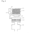
Figure 1 is a schematic longitudinal sectional view
showing the configuration of a hydrogen generator
including a hydrogen purification apparatus according
to Embodiments 1, 3 and 5 of the present invention;
Figure 2 is a schematic longitudinal sectional view
showing the configuration of the hydrogen generator
including the hydrogen purification apparatus according
to Embodiments 2 and 6 of the present invention;
Figure 3 is a schematic longitudinal sectional view
showing the configuration of the hydrogen generator
including the hydrogen purification apparatus according
to Embodiment 4 of the present invention;
Figure 4 is a schematic longitudinal sectional view
showing the configuration of the hydrogen generator
including the hydrogen purification apparatus according
to Embodiment 7 of the present invention; and
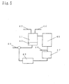
Figure 5 is a schematic diagram showing the
configuration of a fuel cell power generation system with
the hydrogen purification apparatus of the present
invention incorporated therein.
(Description of Symbols)
- 1
- Catalyst body
- 2
- Reaction chamber
- 3, 15
- Reformed gas inlet
- 4, 16
- Reformed gas outlet
- 5, 17
- Diffuser panel
- 6, 18
- Heat insulator
- 11
- First catalyst body
- 12
- First reaction chamber
- 13
- Second catalyst body
- 14
- Second reaction chamber
- 19
- Cooling fan
Best Mode for Carrying out the Invention
Embodiments according to the present invention will
be described below referring to the drawings.
(Embodiment 1)
First, the configuration of the hydrogen
purification apparatus in this embodiment will be
described referring to Figure 1. Furthermore, Figure 1
is a schematic longitudinal sectional view showing the
configuration of the hydrogen purification apparatus in
this embodiment.
In Figure 1, reference numeral 1 denotes a CO shifting
catalyst body (hereinafter also referred to simply as
catalyst body), which has been placed inside a reaction
chamber 2. Reference numeral 3 denotes a reformed gas
inlet, from which the reformed gas is introduced. The
reformed gas reacted in the CO shifting catalyst body
1 is discharged from a reformed gas outlet 4.
Furthermore, a diffuser panel 5 is placed in the
upstream of the catalyst body 1 so that the reformed gas
is flown uniformly. Also, for keeping the reaction
chamber 2 at a fixed temperature, the periphery of some
spaces was covered with a heat insulator 6 made of ceramic
wool as required.
Here, for the catalyst body 1, a material having a
cogierite honeycomb coated with a catalyst with Pt carried
on a complex oxide of zirconium (hereinafter referred
to as Zr) and molybdenum (hereinafter referred to as Mo)
was used.
Operations of the hydrogen purification apparatus
in this embodiment will now be described.
Fuels used for producing the reformed gas to be
supplied to the hydrogen purification apparatus include
natural gas, methanol and gasoline, and reforming methods
include steam reforming in which steam is added, and
partial reforming in which air is added to carry out
reforming, but in this case, the case will be described
where natural gas is subjected to steam reforming to obtain
the reformed gas.
The composition of the reformed gas when natural gas
is subjected to steam reforming more or less varies
depending on the temperature of the reforming catalyst
body, but the average value excluding steam is such that
the content of hydrogen is about 80% by volume, and the
contents of carbon dioxide and carbon monoxide are about
10% by volume, respectively.
Since the reforming reaction for natural gas is
carried out at 500 to 800°C while the shift reaction in
which CO and steam are reacted with each other proceeds
at 150 to 350°C, the reformed gas is supplied after being
cooled just before the reformed gas inlet 3. The
concentration of CO after the CO shifting catalyst body
1 is passed is reduced to about 0.5% by volume, and the
CO is discharged from the reformed gas outlet 4.
The operating principle of the hydrogen purification
apparatus of this embodiment will now be described.
The CO shift reaction is an equilibrium reaction
dependent on temperature, and the concentration of CO
can be reduced as the temperature at which the reaction
is carried out is decreased. On the other hand, when the
temperature is decreased, the reaction on the catalyst
is slowed. Therefore, there is a temperature at which
the concentration of CO takes a minimum value.
Copper based shifting catalysts such as a copper-zinc
catalyst and a copper-chrome catalyst that are used as
CO shifting catalysts in the conventional hydrogen
purification apparatus can undergo the CO shift reaction
at a low temperature of 150 to 250°C, and the concentration
of CO can be reduced to about several hundreds to one
thousand ppm depending on conditions.
However, the copper based catalyst needs to be
activated by circulating reducing gas such as hydrogen
and reformed gas during startup of the apparatus after
the reaction vessel is filled with the catalyst, and its
heat-resistant temperature is as low as about 300°C.
Therefore, the reducing gas should be diluted with an
inert gas or the like before being supplied, or the reaction
should be carried out slowly at a low flow rate in order
to prevent the situation in which temperature is increased
to above the heat-resistant temperature due to the heat
of reaction at the time of activation, and thus it takes
much time to carry out the reaction. Also, at the time
of starting the apparatus, heating should be carried out
slowly for a long time in order to prevent the situation
in which temperature is increased excessively to exceed
the heat-resistant temperature, and thus the copper based
catalyst has a lot of problems for applications where
the apparatus is started and stopped frequently.
On the other hand, in the hydrogen purification
apparatus of this embodiment, a precious metal catalyst
Pt is used for part of the catalyst body 1, and the catalyst
has very high heat resistance compared to the copper based
catalyst, thus eliminating the possibility that the
catalyst is significantly deteriorated even if the
temperature rises to as high as about 500°C at the time
of starting the apparatus. Also, unlike the copper based
catalyst, it is not necessary to carry out long hours
of reduction treatment. Also, even if air is entrained
when the apparatus is stopped, the catalyst is less
significantly deteriorated than the copper based
catalyst.
Also, precious metal catalysts having Pt, Pd, Rh,
Ru and the like as active components have relatively low
reaction selectivity because of high activity.
Therefore, the methanation reaction of CO or carbon
dioxide may also proceed as a secondary reaction of the
CO shift reaction depending on conditions, and thus there
is apprehension that consumption of hydrogen due to the
proceeding methanation reaction reduces efficiency of
the entire apparatus.
However, usually, the methanation reaction becomes
active as the temperature is increased in the temperature
range of from 150 to 450°C at which the CO shift reaction
is carried out, but the production rate of methane also
varies depending on the type of precious metals. This
is because the CO absorption mechanism varies depending
on the type of precious metals, and Pd, Rh and Ru having
CO absorption mechanisms allowing the methanation
reaction to proceed easily cause methane to be produced
at relatively low temperature, thus narrowing the range
of temperature at which the CO shift reaction can be carried
out. On the other hand, the Pt catalyst for use in this
embodiment does not cause the methanation reaction easily,
and thus allows the CO shift reaction to be carried out
in the wide range of temperature. Therefore, there is
no possibility that a large amount of hydrogen is consumed
due to the proceeding methanation reaction, and thus the
hydrogen purification apparatus of this embodiment can
be operated efficiently.
Also, by adding Mo as a promoter, the activity of
the Pt catalyst for the CO shift reaction is improved,
and the methanation reaction can be curbed. This is due
to the effect of changing the state of the oxidized Pt
catalyst into a state in which the shift reaction proceeds
more easily.
Also, the amount of Mo to be added is preferably equal
to or larger than the amount of carried Pt. The catalytic
activity becomes higher as the amount of carried Pt is
increased, but the effect of increasing the amount of
Pt cannot be exerted unless the amount of Mo is equal
to or larger than the amount of Pt.
However, molybdenum oxide has low heat resistance
compared to carriers such as zirconia, and may have its
specific surface area decreased to reduce the catalytic
activity when used under conditions causing the
temperature to rise to above 600°C. Also, it is slightly
water soluble, thus raising a possibility that Mo is leaked
in the long run.
In the case of the hydrogen purification apparatus
of the present invention, a complex oxide with Mo
compounded with Zr, for example, is used as a catalyst
carrier, and thus stability of the catalyst carrier is
improved, and it is unlikely that the catalysts activity
will be reduced. For the ratio between Mo and Zr, heat
resistance is improved to add stability as the content
of Mo decreases (namely, the content of Zr increases),
but the methanation reaction in the high temperature range
proceeds more easily as the content of Mo decreases.
Therefore, the content of Mo is preferably 1% by atom
or larger. However, if the content of Mo is larger than
90% by atom, obtained performance will be limited to the
level almost identical to that of molybdenum oxide.
That is, for the hydrogen purification apparatus of
the present invention, the above described carrier is
comprised of a complex oxide with Zr compounded with at
least one of Mo, W and Re, and an effect similar to that
described above can be obtained even if the content of
elements excluding oxygen in the complex oxide is 1 to
90% by atom with respect to the total amount of the above
described complex oxide.
Furthermore, the method of compounding Zr with Mo
is not particularly limited, and for example, the
coprecipitation process, the sol-gel process, the
alkoxide method and the like may be used. Also, zirconia
may be impregnated with a solution of Mo salt.
Also, in the case where molybdenum oxide and zirconia
are compounded together uniformly in such a manner as
to form a solid solution, stability of the carrier is
improved, and proceeding of the methanation reaction is
curbed. This is because properties of low resistance and
tendencies to cause methanation reaction specific of
respective materials emerge when molybdenum oxide and
zirconia are present without forming a solid solution.
The formed solid solution can be observed by powder X-ray
diffraction measurement, and it can be understood that
the lower the single phase diffraction ray intensity of
molybdenum oxide and zirconia, the more uniformly the
solid solution is formed.
It is necessary to reduce the size of Pt particles
and increase the number of active sites to obtain
sufficient catalytic activity, and for this purpose, it
is preferable that Pt is carried on a metal oxide having
a BET specific surface area of 10 square meters per unit
or larger. Here, the BET specific surface area refers
to a specific surface area determined by a well known
measuring method in which nitrogen is absorbed in powders
to carry out measurements.
The upper limit of the BET specific surface area is
not specified, and similarly high activity can be obtained
even in the case of 100 to 200 square meters per gram,
but if the BET specific surface area is equal to or larger
than 100 square meters per gram, the effect of increased
specific surface area is diminished. If the BET specific
surface area of the metal oxide and complex metal oxide
is smaller than 10 square meters per gram, Pt is not
sufficiently adsorbed and the degree of dispersion of
Pt is reduced, thus making it impossible to obtain
sufficient catalytic activity. Furthermore, because the
particle size of Pt is reduced, the number of active sites
decreases, and thus sufficient activity cannot be
obtained if the amount of carried Pt is reduced.
Also, in this embodiment, the complex oxide with Mo
compounded with Zr is used, but a similar effect can be
obtained even if tungsten (W) and rhenium (Re) are
compounded in place of Mo. These elements have chemical
properties similar to those of Mo, and therefore the effect
of adding these elements is same as the effect of adding
Mo. Also, a similar effect can be obtained even if these
additive elements are used in combination.
Also, in this embodiment, the catalyst body has a
shape of cogierite honeycomb, but a shifting catalyst
body having a similar capability can be obtained even
if the carrier is of pellet type, and it is impregnated
with salt of Pt to prepare a CO shifting catalyst body.
(Embodiment 2)
Embodiment 2 of the present invention will now be
described. In this embodiment, as shown in Figure 2, the
catalyst body-is divided into two stages, and a cooling
unit is provided between the divided catalyst bodies,
and the functional effect of this embodiment is for the
most part similar to that of Embodiment 1. Therefore,
this embodiment will be described focusing on the aspects
different from those of Embodiment 1.
Figure 2 is a schematic longitudinal sectional view
showing the configuration of the hydrogen purification
apparatus according to this embodiment. The catalyst
body is divided into a first catalysis body 11 and a second
catalyst body 13, and a cooling unit is provided between
these catalyst bodies, and the reformed gas is cooled
by a cooling fan 19, thereby making it possible to reduce
the concentration of CO with a small amount of catalyst.
Because the CO reformation reaction is an exothermic
reaction, heat of reaction generated in the upstream of
the catalyst body is transferred to the downstream by
the reformed gas. Therefore, the temperature of the
catalyst body tends to be higher in the downstream, and
even though the concentration of CO is sufficiently
reduced in the upstream, the concentration of CO is
increased again due to a reverse reaction in the downstream
of high temperature. Thus, the reverse reaction can be
curbed by reducing the temperature of the second catalyst
body 13 in the downstream to below the temperature of
the first catalyst body 11.
A two-stage structure is employed in this embodiment,
but the number of stages is not limited, and any structure
allowing the catalyst body in each stage to be controlled
to keep optimal temperature can provide high quality.
For example, the hydrogen purification apparatus
according to this embodiment may be such that the carbon
monoxide-shifting catalyst body is divided into a
plurality of stages, and the divided carbon
monoxide-shifting catalyst bodies are arranged one after
another from the upstream to downstream of the route of
the reformed gas, and a heat releasing unit for the reformed
gas to release heat and a cooling unit to cool at least
one side of the reformed gas are provided between the
carbon monoxide-shifting catalyst bodies, and even such
a structure can bring about effects similar to those
described above.
Also, the cooling fan is used as cooling means, but
cooling by water may also be used.
Example 1 and Example 2 will now be described below
as Examples corresponding to Embodiment 1.
(Example 1)
1% by atom of Pt was carried on metal oxides or complex
oxides 1 to 22 of which compositions are shown in Table
1, respectively. These were applied to cogierite
honeycombs, and were placed as the catalyst body 1 in
the reaction chamber 2 shown in Figure 1.
A reformed gas containing 8% by volume of carbon
monoxide, 8% by volume of carbon dioxide, 20% by volume
of steam and 64% by volume of hydrogen was introduced
at the flow rate of 10 liters per minute from the reformed
gas inlet 3. The reformed gas was reacted with the
catalyst body 1 with its temperature being controlled,
and thereafter the composition of the gas discharged from
the reformed gas outlet 4 was measured by gas
chromatography.
The minimum concentration of CO and the concentration
of methane in the gas after the reaction with the catalyst
temperature of 400°C were measured, and the operation of
stopping and thereafter starting again the apparatus was
repeated ten times, and then the concentration of CO was
measured to observe a change in catalytic activity. The
results thereof are summarized in Table 1.
| Sample No. | Metal Oxide or Complex Metal Oxide | Concentration of CO (%) | Concentration CO after starting and Stopping Ten Times (%) | Concentration of Methane at 400°C (%) |
| 1 | Zirconia | 0.62 | 0.63 | 1.52 |
| 2 | Molybdenum Oxide | 0.13 | 0.75 | 0.01 |
| 3 | Tungsten Oxide | 0.14 | 0:88 | 0.02 |
| 4 | Rhenium Oxide | 0.13 | 0.78 | 0.01 |
| 5 | Mo0.95Zr0.05Ox | 0.13 | 0.64 | 0.03 |
| 6 | Mo0.9Zr0.1Ox | 0.13 | 0.15 | 0.05 |
| 7 | Mo0.5Zr0.5Ox | 0.13 | 0.14 | 0.10 |
| 8 | Mo0.01Zr0.99Ox | 0.14 | 0.15 | 0.50 |
| 9 | Mo0.005Zr0.995Ox | 0.50 | 0.52 | 1.02 |
| 10 | Mo0.003Zr0.997Ox | 0.55 | 0.57 | 1.50 |
| 11 | W0.95Zr0.05Ox | 0.14 | 0.65 | 0.04 |
| 12 | W0.9Zr0.1Ox | 0.14 | 0.16 | 0.07 |
| 13 | W0.5Zr0.5Ox | 0.14 | 0.15 | 0.12 |
| 14 | W0.01Zr0.99Ox | 0.15 | 0.16 | 0.52 |
| 15 | W0.005Zr0.995Ox | 0.52 | 0.53 | 1.10 |
| 16 | W0.003Zr0.997Ox | 0.56 | 0.57 | 1.51 |
| 17 | Re0.95Zr0.05Ox | 0.13 | 0.64 | 0.01 |
| 18 | Re0.9Zr0.1Ox | 0.14 | 0.15 | 0.04 |
| 19 | Re0.5Zr0.5Ox | 0.15 | 0.14 | 0.12 |
| 20 | Re0.01Zr0.99Ox | 0.15 | 0.14 | 0.51 |
| 21 | Re0.005Zr0.995Ox | 0.49 | 0.52 | 1.01 |
| 22 | Re0.003Zr0.997Ox | 0.49 | 0.57 | 1.50 |
The experimental results shown in Table 1 support
the aforesaid facts as described below. Molybdenum oxide
is very active to the shift reaction, and is capable of
curbing the methanation reaction, but the catalytic
activity of molybdenum oxide is easily reduced by the
repetitive starting and stopping of the apparatus,
compared to zirconia. Also, when the complex oxide with
Zr compounded with Mo is used as a catalyst carrier, the
smaller the content of Mo, (1) the likelier it is that
the catalytic activity is not reduced, but (2) the more
easily the methanation reaction in the high temperature
range proceeds, for example.
Furthermore, W and Re have chemical natures similar
to those of Mo. Therefore, even if a complex oxide with
W or Re compounded with Zr is used, experimental results
similar to those obtained by using a complex oxide with
Mo compounded with Zr can be obtained.
(Example 2)
Measurements were carried out in the same way as
Example 1 for samples of No. 23 to 32 carrying 0.5 to
3% by atom of Pt with respect to complex oxides in which
the contents of Mo are 1% by atom and 2% by atom. The
results thereof are summarized in Table 2.
| Sample No. | Metal Oxide or Complex Metal Oxide | Amount of Carried Pt (mol%) | Concentration of Co (%) | Concentration of Methane at 400°C(%) |
| 23 | Mo0.01Zr0.99Ox | 0.5 | 0.30 | 0.30 |
| 24 | Mo0.01Zr0.99Ox | 1.0 | 0.14 | 0.50 |
| 25 | Mo0.01Zr0.99Ox | 1.5 | 0.13 | 0.70 |
| 26 | Mo0.01Zr0.99Ox | 2.0 | 0.13 | 0.90 |
| 2 7 | Mo0.01Zr0.99Ox | 3.0 | 0.13 | 1.20 |
| 28 | Mo0.02Zr0.98Ox | 0.5 | 0.29 | 9.28 |
| 29 | Mo0.02Zr0.98Ox | 1.0 | 0.13 | 0.30 |
| 30 | Mo0.02Zr0.98Ox | 1.5 | 0.10 | 0.35 |
| 31 | Mo0.02Zr0.98Ox | 2.0 | 0.08 | 0.40 |
| 32 | Mo0.02Zr0.98Ox | 3.0 | 0.08 | 0.70 |
The experimental results shown in Table 2 support
the aforesaid facts as described below. As the amount
of carried Pt is increased, the concentration of CO can
be reduced to a lower level, but if the amount of Pt becomes
larger than the amount of added Mo, the activity is no
longer improved, and only the methanation activity is
increased.
Example 3 will now be described below as Example
corresponding to Embodiment 2.
(Example 3)
1% by atom of Pt was carried on a complex oxide in
which the ratio between Zr and Mo shown in Sample No.
7 in Table 1 used in Example 1 is 1:1. Cogierite honeycombs
were coated with this material, and were placed in a first
reaction chamber 12 and a second reaction chamber 14 shown
in Figure 2, respectively, with the total volume of the
first catalyst body 11 and the second catalyst body 13
being identical to that of Example 1. A reformed gas
containing 8% by volume of carbon monoxide, 8% by volume
of carbon dioxide, 20% by volume of steam and 64% by volume
of hydrogen was introduced at the flow rate of 10 liters
per minute from a reformed gas inlet 15. The minimum
concentration of CO and the concentration of methane in
the gas after the reaction with the temperature of the
first catalyst body 11 being 400°C were 0.09% by volume
and 0.06% by volume, respectively. In addition, the
operation of stopping and thereafter starting again the
apparatus was carried out ten times , and the concentration
of CO was measured to observe a change in catalytic activity,
and it was found that the concentration was 0 . 11 % by volume .
Comparative Example 1 will now be described below
as Comparative Example for Examples 1 to 3.
(Comparative Example 1)
In this Comparative Example, a conventional
copper-zinc catalyst was used as the catalyst body 1 in
place of the complex oxide with Pt carried thereon, and
this was placed in the chamber 2 shown in Figure 1 in
the same way as Example 1. A reformed gas containing 8%
by volume of carbon monoxide, 8% by volume of carbon dioxide,
20% by volume of steam and 64% by volume of hydrogen was
introduced at the flow rate of 10 liters per minute from
the reformed gas inlet 3. The reformed gas was reacted
with the catalyst body 1 with its temperature being
controlled, and thereafter the composition of the gas
discharged from the reformed gas outlet 4 was measured
by gas chromatography to find that the minimum
concentration of CO was 0.08% by volume. In addition,
the operation of stopping and thereafter starting again
the apparatus was repeated ten times, and the
concentration of CO was measured to observe a change in
catalytic activity, and it was found that the minimum
concentration of CO was 4% by volume.
In this way, in the case where the catalyst body in
this Comparative Example is used, the concentration of
CO after repeating the startup and stop of the apparatus
ten times is significantly high compared to the case where
the catalyst body in the aforesaid Example is used.
Therefore, as described previously, it has been
demonstrated that the hydrogen purification apparatus
of the present invention is hardly influenced by entrained
oxygen even if the startup and stop of operation is repeated,
and thus can be operated stably over an extended period.
As apparent from what has been described above, the
present invention is a hydrogen purification apparatus
comprising a reformed gas supplying unit supplying at
least, for example, hydrogen gas, carbon monoxide and
steam, and a reaction chamber having a carbon monoxide
shifting catalyst body located in the downstream of the
above described reformed gas supplying unit, and the above
described carbon monoxide shifting catalyst body is a
material in which at least Pt is carried on a complex
oxide with at least Mo or W or Re compounded with Zr,
for example.
At this time, it is preferable that the complex oxide
has as its composition ratio 1 to 90% by atom of Mo and
10 to 99% by atom of Zr.
Furthermore, the element carried on the complex oxide
of the present invention is Pt in the case of this
embodiment described above, but it is not limited thereto,
and in short, may be one of Pt, Pd, Rh and Ru. However,
Pt is most preferably used because a precious metal
catalyst having Pd, Rh, Ru and the like as active components
may allow the methanation reaction to proceed as described
previously. Therefore, when Pd, Rh, Ru and the like are
used, it is desirable that the above described complex
oxide carries at least Pt and has these elements added
therein with Pt as a main component.
In this way, the hydrogen purification apparatus of
the present invention has improved endurance of the CO
transforming catalysis body, and thus can be operated
stably even if the startup and stop of the apparatus is
repeated.
(Embodiment 3)
First, the configuration of the hydrogen
purification apparatus in this embodiment will be
described referring to Figure 1.
In Figure 1, reference numeral 1 denotes a CO shifting
catalyst body (hereinafter also referred to simply as
catalyst body), which has been placed inside a reaction
chamber 2. Reference numeral 3 denotes a reformed gas
inlet, from which the reformed gas is introduced. The
reformed gas reacted in the catalyst body 1 is discharged
from a reformed gas outlet 4.
Furthermore, a diffuser panel 5 is placed in the
upstream of the catalyst body 1 so that the reformed gas
is flown uniformly. Also, for keeping the reaction vessel
at a fixed temperature, the periphery of some spaces was
covered with a heat insulator 6 made of ceramic wool as
required.
Here, the catalyst body 1 was prepared by coating
a cogierite honeycomb with a material in which Ce and
Pt are carried on Y-type zeolite of SiO2/Al2O3 = 5 (molar
ratio) (forger site type zeolite with silica-alumina
ratio equal to or larger than 4).
Operations of the hydrogen purification apparatus
in this embodiment will now be described. Fuels used for
producing the reformed gas to be supplied to the hydrogen
purification apparatus include natural gas, methanol and
gasoline, and reforming methods include steam reforming
in which steam is added, and partial reforming in which
air is added to carry out reforming, but in this case,
the case will be described where natural gas is subjected
to steam reforming to obtain the reformed gas.
The composition of the reformed gas when natural gas
is subjected to steam reforming more or less varies
depending on the temperature of the reforming catalyst
body, but the average value excluding steam is such that
the content of hydrogen is about 80% by volume, and the
contents of carbon dioxide and carbon monoxide are about
10% by volume, respectively.
Since the reforming reaction for natural gas is
carried out at 500 to 800°C while the shift reaction in
which CO and steam are reacted with each other proceeds
at 150 to 350°C, the reformed gas is supplied after being
cooled just before the reformed gas inlet 3. The
concentration of CO after the catalyst body 1 is passed
is reduced to about 1% by volume, and the CO is discharged
from the reformed gas outlet 4.
The operating principle of the hydrogen purification
apparatus of this embodiment will now be described. The
CO shift reaction is an equilibrium reaction dependent
on temperature, and the concentration of CO can be reduced
as the temperature at which the reaction is carried out
is decreased. On the other hand, when the temperature
is decreased, the reaction on the catalyst is slowed.
Therefore, there is a temperature at which the
concentration of CO takes a minimum value.
Copper based shifting catalysts such as a copper-zinc
catalyst and a copper-chrome catalyst that are used as
CO shifting catalysts in the conventional hydrogen
purification apparatus can undergo the CO shift reaction
at a low temperature of 150 to 250°C, and the concentration
of CO can be reduced to about several hundreds to one
thousand ppm depending on conditions.
However, the copper based catalyst needs to be
activated by circulating reducing gas such as hydrogen
and reformed gas after the reaction vessel is filled with
the catalyst, and its heat-resistant temperature is as
low as about 300°C. Therefore, the reducing gas should
be diluted with an inert gas or the like before being
supplied, or the reaction should be carried out slowly
at a low flow rate in order to prevent the situation in
which temperature is increased to above the
heat-resistant temperature due to the heat of reaction
at the time of activation, and thus it takes much time
for activation. Also, at the time of starting the
apparatus, heating should be carried out slowly for a
long time in order to prevent the situation in which
temperature is increased excessively to exceed the
heat-resistant temperature, and thus the copper based
catalyst has a lot of problems for applications where
the apparatus is started and stopped frequently.
On the other hand, in the hydrogen purification
apparatus of the present invention, a catalyst body having
a precious metal as an active component is used as the
catalyst body 1, thus eliminating the possibility that
the catalyst is significantly deteriorated even if the
temperature rises to as high as about 500°C at the time
of starting the apparatus. Also, unlike the copper based
catalyst, it is not necessary to carry out long hours
of reduction treatment for curbing heat generation by
heat of the reduction reaction because the catalyst body
1 has high heat resistance . Also , even if air is entrained
when the apparatus is stopped, the catalyst is less
significantly deteriorated than the copper based
catalyst.
Also, by using zeolite as a carrier, deterioration
is also prevented because the active component is carried
in high dispersion and zeolite as a carrier is strongly
interacted with the precious metal.
Zeolite generally has silica and alumina as main
components, and exhibits a variety of properties such
as solid acidity and hydrophobicity depending on the ratio
between the Al atom in trivalent electronic state and
the Si atom in tetravalent electronic state. Zeolite used
in this embodiment, of which SiO2/Al2O3 ratio equals 5,
is a hydrophobic zeolite having low affinity with water.
At the time of starting the hydrogen purification
apparatus, a gas containing a large amount of steam may
be supplied to the apparatus before the temperature of
the apparatus rises to a sufficiently high level.
Therefore, in the past, active sites were covered with
water condensed in the catalyst body, and thus it took
much time before the reaction started, or the catalyst
was heated by a heater. On the other hand, in the present
invention, because hydrophobic zeolite is used, there
is no possibility that water causes reduction in catalytic
activity, and the reaction can be started quickly at a
relatively low temperature.
Furthermore, precious metal catalysts having Pt, Pd,
Rh, Ru and the like as active components have relatively
low reaction selectivity because of high activity.
Therefore, the methanation reaction of CO or carbon
dioxide may also proceed as a secondary reaction of the
CO shift reaction depending on conditions, and thus there
is apprehension that consumption of hydrogen due to the
proceeding methanation reaction reduces efficiency of
the entire apparatus.
Usually, the methanation reaction becomes active as
the temperature is increased in the temperature range
of from 150 to 450°C at which the CO shift reaction is
carried out, but the production rate of methane also varies
depending on the type of precious metals. This is because
the CO absorption mechanism varies depending on the type
of precious metals, and Pd, Rh and Ru having CO adsorption
mechanisms allowing the methanation reaction to proceed
easily cause methane to be produced at relatively low
temperature, thus narrowing the range of temperature at
which the CO shift reaction can be carried out. On the
other hand, the Pt catalyst for use in this embodiment
does not cause the methanation reaction easily, and thus
allows the CO shift reaction to be carried out in the
wide range of temperature. Therefore, there is no
possibility that a large amount of hydrogen is consumed
due to the proceeding methanation reaction, and thus the
hydrogen purification apparatus of this embodiment can
be operated efficiently.
Also, for the amount of precious metal to be carried,
any amount keeping the degree of dispersion of the precious
metal at a high level and allowing required activity to
be exhibited is preferable. The precious metal particles
are enlarged to increase the amount of precious metal
not contributing to the reaction as the content of precious
metal is increased, and conversely, sufficient activity
cannot be obtained if the content of precious metal is
small. Therefore, the content of precious metal is
preferably in the range of 0.1 to 5% by weight with respect
to the amount of catalyst carrier, as in the case of usual
precious metal catalysts for combustion and for
purification of exhausts.
Also, Ce helps curb the methanation reaction on the
precious metal catalyst. For the precious metal catalyst,
alumina, silica, titanium oxide and the like are usually
used as a catalyst carrier, but when they are used for
the shift reaction, the methanation reaction tends to
proceed at a temperature of 300°C or higher. If Ce is
made to coexist with the precious metal, the methanation
reaction hardly proceeds even at a temperature as high
as 450°C. A similar effect can be obtained by adding a
transition metal selected from Cu, Fe, Cr, Re, Mo and
W instead of Ce.
Cu, Fe, Cr, Ce, Re, Mo and W are added preferably
in the amount allowing them to be carried in pores of
zeolite efficiently, and the most effective amount is
0.5 to 10% by weight.
Also, zeolite of Y-type structure is used in this
embodiment, the structure of zeolite is not particularly
limited, and may be of L-type, mordenite type, ZSM-5 type
or beta-type as long as it has pores sufficiently large
for reacting gases (CO and water molecules). They have
pores of 0.5 to 1 nm, and allow active sites in the pores
to act effectively, thus making it possible to obtain
high activity.
Also, zeolite in which the silica-alumina ratio of
SiO2/Al2O3 equals 5 is used in this embodiment, but as
long as the ratio equals 4 or greater, high performance
can be obtained. Also, hydrohobicity is increased to
bring about preferred properties as the ratio of silica
is increased, but if the silica-alumina ratio of SiO2/Al2O3
is greater than 200, the properties remain unchanged even
though the ratio of silica is increased.
Also, as for the shape of catalyst body, a cogierite
honeycomb coated with the catalysis is used in this
embodiment, but even if zeolite is shaped into pellets,
and is impregnated with a precious metal salt to prepare
a CO shifting catalyst body, a CO shifting catalyst body
having similar performance can be obtained.
Also, Ce and Pt are carried on zeolite in this
embodiment, but even if a metal oxide such as cerium oxide
with a precious metal carried thereon is mixed with zeolite,
a similar effect can be obtained.
(Embodiment 4)
Embodiment 4 of the invention will now be described.
This embodiment is similar to Embodiment 3 except that
an air supplying unit 25 (or oxidizing gas supplying unit)
is provided in the upstream of a catalyst body 21 as shown
in Figure 3.
Figure 3 is a schematic cross sectional view showing
the configuration of the hydrogen purification apparatus
according to this embodiment. In Figure 3, reference
numeral 21 denotes a CO shifting catalyst body
(hereinafter also referred to simply as catalyst body),
which has been placed inside a reaction chamber 22.
Reference numeral 23 denotes a reformed gas inlet, from
which the reformed gas is introduced. The reformed gas
reacted in the catalyst body 21 is discharged from a
reformed gas outlet 24.
Furthermore, a diffuser panel 26 is placed in the
upstream of the catalyst body 21 so that the reformed
gas is flown uniformly. Also, for keeping the reaction
vessel at a fixed temperature, the periphery of some spaces
was covered with a heat insulator 27 made of ceramic wool
as required.
Here, the catalyst body 21 was prepared by coating
a cogierite honeycomb with a material in which Ce and
Pt are carried on Y-type zeolite of SiO2/Al2O3 = 5 (molar
ratio) (forger site type zeolite with silica-alumina
ratio equal to or larger than 4).
By supplying air from the air supplying unit 25,
hydrogen or carbon monoxide in the reformed gas is oxidized
with the catalyst body 21. Usually, water is condensed
on the catalyst, and the oxidization reaction poorly
proceeds until the temperature of the catalyst body 21
rises to a sufficient level during startup. For this
reason, heat generation does not occur even if air is
added, and therefore it takes much time for startup. Here
in this embodiment, hydrophobic zeolite is contained in
the catalyst body 21, and thus the oxidization reaction
proceeds on the catalyst body 21 even if a large amount
of steam is contained, as during startup of the apparatus,
and thus the temperature of the catalyst body 21 rises
quickly. Furthermore, the amount of air to be added varies
depending on the configuration of the apparatus and the
like, and is not particularly limited, but the amount
of air should be selected so that the temperature of the
catalyst rises quickly, and the temperature of the
catalyst body does not rise excessively.
Also, if Cu is carried on (or contained in) zeolite
used in the catalyst body 21, the supplied air oxidizes
Cu to generate heat at a temperature lower than the
temperature at which the oxidization reaction of the
catalyst is started, and therefore the temperature of
the catalyst body 21 rises more quickly. When the supply
of air is stopped, copper once oxidized is reduced again
by the reformed gas, and is therefore returned to its
original metal state, and can generate heat again at the
next startup.
Embodiments 4 and 5 will now be described below as
the Example corresponding to Embodiment 3.
(Example 4)
As shown in Table 3, 1% by weight of Cu, Fe, Cr, Ce,
Re, Mo and W were carried, and 1% by weight of precious
metals (the specific type of precious metal is described
in Table) were carried, respectively, to Y-type zeolite
(described as Y in Table) with the silica-alumina ratio
of SiO2/Al2O3 equal to 5. 1% by weight of Ce was carried,
and 1% by weight of Pt was carried on L-type, mordenite-type,
ZSM 5-type and beta-type zeolite (described as L. M. ZSM5
and β, respectively, in Table) with the silica-alumina
ratio of SiO2/Al2O3 equal to 5, respectively. Cogierite
honeycombs were coated with these materials, and placed
in the reaction chamber 2 shown in Figure 1.
A reformed gas containing 8% by volume of carbon
monoxide, 8% by volume of carbon dioxide, 20% by volume
of steam and 64% by volume of hydrogen was introduced
at the flow rate of 10 liters per minute from the reformed
gas inlet 3. The reformed gas was reacted with the
catalyst 1 with its temperature being controlled, and
thereafter the composition of the gas discharged from
the reformed gas outlet 4 was measured by gas
chromatography.
The minimum concentration of CO when the temperature
is changed and the concentration of methane in the gas
after the reaction with the catalyst temperature of 400°C
were measured, and the operation of stopping and
thereafter starting again the apparatus was repeated ten
times, and then the minimum concentration of CO was
measured to observe a change in catalytic activity. The
results thereof are summarized in Table 3.
| Sample No. | Sample | Concentration of CO (%) | Concentration of CO after Starting and Stopping Ten Times (%) | Concentration of Methane at 400°C (%) |
| 1 | Pt/Cu/Y | 0.30 | 0.40 | 0.01 |
| 2 | Pt/Fe/Y | 0.60 | 0.62 | 0.02 |
| 3 | Pt/Cr/Y | 0.90 | 0.91 | 0.03 |
| 4 | Pt/Ce/Y | 0.40 | 0.40 | 0.03 |
| 5 | Pt/Re/Y | 0.45 | 0.60 | 0.04 |
| 6 | Pt/Mo/Y | 0.55 | 0.65 | 0.02 |
| 7 | Pt/W/Y | 0.70 | 0.75 | 0.02 |
| 8 | Ru/Ce/Y | 0.90 | 0.92 | 1.70 |
| 9 | Rh/Fe/Y | 0.80 | 0.82 | 1.02 |
| 10 | Pd/Fe/Y | 0.70 | 0.71 | 0.70 |
| 11 | Pt/Ce/L | 0.41 | 0.41 | 0.03 |
| 12 | Pt/Ce/M | 0.42 | 0.42 | 0.03 |
| 13 | Pt/Ce/ZSM5 | 0.40 | 0.40 | 0.03 |
| 14 | Rt/Ce/β | 0.43 | 0.43 | 0.03 |
The experimental results shown in Table 3 support
the aforesaid facts as described below. The Y-type
zeolite carrying Cu, Fe, Cr, Ce, Re, Mo and W and Pt is
highly active, and is capable of curbing the methanation
reaction. Particularly, Ce is the most effective. Also,
if Ru, Pd and Rh are used in place of Pt, the methanation
reaction tends to occur to increase the concentration
of methane.
Also, even if L-type, mordenite-type, ZSM 5-type and
beta-type zeolite is used, an effect similar to that of
Y-type zeolite can be obtained.
(Example 5)
For catalyst bodies whose zeolite has the
silica-alumina ratio of 1 to 1000 as shown in Table 4,
in Pt/Ce/Y type (forger site type) zeolite shown in Sample
4 in Table 3 used in Example 4, the cogierite honeycomb
was coated with the catalyst body, and was placed in the
reaction chamber 2 shown in Figure 1 in the same way as
Example 4.
The time elapsed before the temperature of the
catalyst body 1 rose to reduce the concentration of CO
to below 1% by volume after introduction of a reformed
gas containing 8% by volume of carbon monoxide, 8% by
volume of carbon dioxide, 20% by volume of steam and 64%
by volume of hydrogen was introduced at the flow rate
of 10 liters per minute from the reformed
gas inlet 3
was started (startup time) was measured. The results
thereof are summarized in Table 4.
| Sample No. | Silica/Alumina Ratio | Startup Time (min) |
| 15 | 1 | 50 |
| 16 | 2 | 35 |
| 17 | 3 | 20 |
| 18 | 4 | 6 |
| 19 | 5 | 5 |
| 20 | 10 | 4 |
| 21 | 50 | 2 |
| 22 | 200 | 2 |
| 23 | 1000 | 2 |
Examples 6 and 7 will now be described below as the
Example corresponding to Embodiment 4.
(Example 6)
The startup time was measured in the same way as
Example 5, while the air supplying unit 14 was provided
in the upstream of the catalyst body 21 as shown in Figure
3, and air was supplied therefrom at the flow rate of
0.2 liters per minute . The results thereof are summarized
in Table 5.
| Sample No. | Silica/Alumina Ratio | Startup Time (min) |
| 24 | 1 | 35 |
| 25 | 2 | 25 |
| 26 | 3 | 18 |
| 27 | 4 | 3 |
| 28 | 5 | 2 |
| 29 | 10 | 1 |
| 30 | 50 | 1 |
| 31 | 200 | 1 |
| 32 | 1000 | 1 |
For catalyst bodies whose zeolite has the
silica-alumina ratio of 1 to 1000 as shown in Table 6,
in Pt/Cu/Y type zeolite shown in
Sample 1 in Table 3 used
in Example 4, the startup time was measured in the same
way as Example 6. The results thereof are summarized in
Table 6.
| Sample No. | Silica/Alumina Ratio | Startup Time (min) |
| 33 | 1 | 25 |
| 34 | 2 | 15 |
| 35 | 3 | 10 |
| 36 | 4 | 2 |
| 37 | 5 | 1 |
| 38 | 10 | 0.5 |
| 39 | 50 | 0.5 |
| 40 | 200 | 0.5 |
| 41 | 1000 | 0.5 |
Comparative Examples 2 to 4 will now be described
below as the Comparative Example corresponding to
Examples 4 to 7.
(Comparative Example 2)
Oxides and materials with 1% by weight of precious
metal carried on alumina 42 to 47, of which compositions
are shown in Table 7, were used as the
catalyst body 1
in place of the materials with rare earth metals or
transition metals carried on zeolite of the present
invention, and they were placed in the
reaction chamber
2 shown in Figure 1 in the same way as Example 4. A reformed
gas containing 8% by volume of carbon monoxide, 8% by
volume of carbon dioxide, 20% by volume of steam and 64%
by volume of hydrogen was introduced at the flow rate
of 10 liters per minute from the reformed
gas inlet 3.
The reformed gas was reacted with the
catalyst 1 with
its temperature being controlled, and thereafter the
composition of the gas discharged from the reformed
gas
outlet 4 was measured by gas chromatography. The minimum
concentration of CO when the temperature is changed and
the concentration of methane in the gas after the reaction
with the catalyst temperature of 400°C were measured, and
the operation of stopping and thereafter starting again
the apparatus was repeated ten times, and then the minimum
concentration of CO was measured to observe a change in
catalytic activity. The results thereof are summarized
in Table 7.
| Sample No. | Metal Oxide or Complex Oxide | Concentration of CO (%) | Concentration of CO after Starting and Stopping Ten Times (%) | Concentration of Methane at 400°C (%) |
| 42 | Fe0.9Cr0.1Ox | 3.5 | 3.5 | 0.004 |
| 43 | Copper-Zinc | 0.1 | 6.2 | 0.001 |
| 44 | Pt/ Alumina | 2.1 | 2.1 | 1.20 |
| 45 | Ru/Alumina | 1.9 | 1.9 | 5.5 |
| 46 | Pd/Alumina | 2.5 | 2.5 | 1.81 |
| 47 | Rh/Alumina | 2.0 | 2.0 | 4.5 |
1% by weight of Pt was carried on cerium oxide in
place of the Pt/Ce/Y type zeolite shown in Sample 4 in
Table 3 used in Example 4, and the cogierite honeycomb
was coated with the material in the same way as in Example
4 , and was placed in the reaction chamber 2 shown in Figure
1.
The time elapsed before the temperature of the
catalyst body 1 rose to reduce the concentration of CO
to below 1% by volume after introduction of a reformed
gas containing 8% by volume of carbon monoxide, 8% by
volume of carbon dioxide, 20% by volume of steam and 64%
by volume of hydrogen was introduced at the flow rate
of 10 liters per minute from the reformed gas inlet 3
was started (startup time) was measured, and as a result
it was found that the startup time equaled 55 minutes.
(Comparative Example 4)
The startup time was measured in the same way as
Comparative Example 3, while the air supplying unit 25
was provided in the upstream of the catalyst body 21 as
shown in Figure 3 in Comparative Example 3, and air was
supplied therefrom at the flow rate of 0.2 liters per
minute, and as a result it was found that the startup
time equaled 40 minutes.
In this way, the following fact is supported if the
catalyst body in this Comparative Example is used. The
complex oxide of iron and chrome not containing a precious
metal is not capable of reducing CO sufficiently, and
the copper-zinc catalyst has high initial activity, but
the activity is reduced considerably if the operation
is repeatedly started and stopped. Also, for the catalyst
body with a precious metal carried on alumina , the activity
is not reduced, but the concentration of methane at 400°C
is high. Also, the startup time could be shortened by
using zeolite.
As apparent from what has been described above, in
this way, the hydrogen purification apparatus of the
present invention has improved endurance of the CO
shifting catalyst body, and can be operated stably even
if the apparatus is started and stopped repeatedly, and
is capable of reducing the startup time.
(Embodiment 5)
First, referring to Figure 1, the configuration of
the hydrogen purification apparatus in this embodiment
will be described referring to Figure 1.
In Figure 1, reference numeral 1 denotes a CO shifting
catalyst body (hereinafter also referred to simply as
catalyst body), which has been placed inside a reaction
chamber 2. Reference numeral 3 denotes a reformed gas
inlet, from which the reformed gas is introduced. The
reformed gas reacted in the CO shifting catalyst body
1 is discharged from a reformed gas outlet 4.
Furthermore, a diffuser panel 5 is placed in the
upstream of the catalyst body 1 so that the reformed gas
is flown uniformly. Also, for keeping the reaction vessel
at a fixed temperature, the periphery of some spaces was
covered with a heat insulator 6 made of ceramic wool as
required.
Here, for the catalyst body 1, a material having a
cogierite honeycomb coated with a catalyst with Pt carried
on a complex oxide of iron (hereinafter referred to as
Fe) and chrome (hereinafter referred to as Cr) was used.
Operations of the hydrogen purification apparatus
in this embodiment will now be described.
Fuels used for producing the reformed gas to be
supplied to the hydrogen purification apparatus include
natural gas, methanol and gasoline, and reforming methods
include steam reforming in which steam is added, and
partial reforming in which air is added to carry out
reforming, but in this case, the case will be described
where natural gas is subj ected to steam reforming to obtain
the reformed gas.
The composition of the reformed gas when natural gas
is subjected to steam reforming more or less varies
depending on the temperature of the reforming catalyst
body, but the average value excluding steam is such that
the content of hydrogen is about 80% by volume, and the
contents of carbon dioxide and carbon monoxide are about
10% by volume, respectively.
Since the reforming reaction for natural gas is
carried out at 500 to 800°C while the shift reaction in
which CO and steam are reacted with each other proceeds
at 150 to 300°C, the reformed gas is supplied after being
cooled just before the reformed gas inlet 3. The
concentration of CO after the CO shifting catalyst body
1 is passed is reduced to about 1% by volume, and the
CO is discharged from the reformed gas outlet 4.
The operating principle of the hydrogen purification
apparatus of this embodiment will now be described.
The CO shift reaction is an equilibrium reaction
dependent on temperature, and the concentration of CO
can be reduced as the temperature at which the reaction
is carried out is decreased. On the other hand, when the
temperature is decreased, the reaction on the catalyst
is slowed. Therefore, there is a temperature at which
the concentration of CO takes a minimum value.
Copper based shifting catalysts such as a copper-zinc
catalyst and a copper-chrome catalyst that are used as
CO shifting catalysts in the conventional hydrogen
purification apparatus can undergo the CO shift reaction
at a low temperature of 150 to 250°C, and the concentration
of CO can be reduced to about several hundreds to one
thousand ppm depending on conditions.
However, as described in the section of prior art,
the copper based catalyst needs to be activated by
circulating reducing gas such as hydrogen and reformed
gas after the reaction vessel is filled with the catalyst,
and its heat-resistant temperature is as low as about
300°C. Therefore, the reducing gas should be diluted with
an inert gas or the like before being supplied, or the
reaction should be carried out slowly at a low flow rate
in order to prevent the situation in which temperature
is increased to above the heat-resistant temperature due
to the heat of reaction at the time of activation, and
thus it takes much time to carry out the reaction. Also,
at the time of starting the apparatus, heating should
be carried out slowly for a long time in order to prevent
the situation in which temperature is increased
excessively to exceed the heat-resistant temperature,
and thus the copper based catalyst has a lot of problems
for applications where the apparatus is started and
stopped frequently.
On the other hand, in the hydrogen purification
apparatus of the present invention, a catalyst body with
Pt carried on the complex oxide of Fe and Cr having high
heat resistance is used as the catalyst body 1, thus
eliminating the possibility that the catalyst is
significantly deteriorated even if the temperature rises
to as high as about 500°C at the time of starting the
apparatus. Also, unlike the copper based catalyst, it
is not necessary to carry out long hours of reduction
treatment for curbing heat generation by heat of the
reduction reaction because the catalyst body 1 has high
heat resistance. Also, even if air is entrained when the
apparatus is stopped, the catalyst is less significantly
deteriorated than the copper based catalyst.
The oxides of Fe and Cr exhibit activity for the shift
reaction even with each single oxide, but because of low
reaction velocity, they should be used at a high
temperature of 400°C or higher allowing the reaction
velocity to be enhanced, or they should be used at a low
space velocity (SV) with a large amount of catalyst. If
they are used at high temperature, the equilibrium
concentration of CO is increased, thus making it
impossible to reduce CO sufficiently. Also, if a large
amount of catalyst is used, miniaturization of the
apparatus becomes difficult. If Fe and Cr are compounded
together, the heat resistance is improved, and the
oxidation-reduction of the oxide associated with the
reaction proceeds smoothly, and therefore the reaction
velocity is enhanced, and activity is exhibited even in
the temperature range around 350°C, but the concentration
of CO can be reduced to only about 2% by volume at best,
and thus the activity is not sufficiently high.
Here, if a precious metal is added to the complex
oxide of Fe and Cr, the reaction velocity is enhanced,
and thus activity is exhibited even in the temperature
range of about 200 to 300°C. This is due to the fact that
CO is highly adsorptive for the precious metal, and that
the precious metal promotes oxidation and reduction of
Fe and Cr.
Furthermore, precious metal catalysts having Pt, Pd,
Rh, Ru and the like as active components have relatively
low reaction selectivity because of high activity.
Therefore, the methanation reaction of CO or carbon
dioxide may also proceed as a secondary reaction of the
CO shift reaction depending on conditions, and thus there
is apprehension that consumption of hydrogen due to the
proceeding methanation reaction reduces efficiency of
the entire apparatus.
Usually, the methanation reaction becomes active as
the temperature is increased in the temperature range
of from 150 to 450°C at which the CO shift reaction is
carried out, but the production rate of methane also varies
depending on the type of precious metals. This is because
the CO adsorption mechanism varies depending on the type
of precious metals, and Pd, Rh and Ru having CO adsorption
mechanisms allowing the methanation reaction to proceed
easily cause methane to be produced at relatively low
temperature, thus narrowing the range of temperature at
which the CO shift reaction can be carried out. On the
other hand, the Pt catalyst for use in this embodiment
does not cause the methanation reaction easily, and thus
allows the CO shift reaction to be carried out in the
wide range of temperature. Therefore, there is no
possibility that a large amount of hydrogen is consumed
due to the proceeding methanation reaction, and thus the
hydrogen purification apparatus of this embodiment can
be operated efficiently.
Also, Fe and Cr help curb the methanation reaction
on the precious metal catalyst. For the precious metal
catalyst, alumina, silica, titanium oxide and the like
are usually used as a catalyst carrier, but when they
are used for the shift reaction, the methanation reaction
tends to proceed at a temperature of 300°C or higher. If
the oxide of Fe and Cr is used as a catalyst carrier,
the methanation reaction hardly proceeds even at a
temperature as high as 450°C.
In the case of the hydrogen purification apparatus
of the present invention, a complex oxide with Fe
compounded with Cr is used as a catalyst carrier, and
thus stability of the catalyst carrier is improved, and
it is unlikely that the catalysts activity will be reduced.
For the ratio between Fe and Cr, heat resistance is
reduced as the content of Cr decreases (namely, the content
of Fe increases). Therefore, it is preferable that the
content of Cr is 1% by atom or larger with respect to
Fe. However, if the content of Cr is larger than 50% by
atom, obtained performance will be limited to the level
almost identical to that of chrome oxide. That is, the
hydrogen purification apparatus can bring about an effect
similar to that described above if the composition ratio
of elements in the oxide excluding oxygen is such that
the content of Cr is 1 to 50 percent by atom with respect
to the content of Fe.
Furthermore, the method of compounding Cr with Fe
is not particularly limited, and for example, the
coprecipitation process, the sol-gel process, the
alkoxide method and the like may be used. Also, iron oxide
may be impregnated with a solution of Cr salt.
Also, in this embodiment, a complex oxide with Cr
compounded with Fe is used, but even if, instead thereof,
amaterial with Fe and Cr compounded with a catalyst carrier
having a large specific surface area such as alumina,
silica alumina, zirconia or the like is used, a similar
effect can be obtained.
Also, in this embodiment, for the shape of catalyst
body, a catalyst body with a cogierite honeycomb coated
with a catalyst is used, but a CO shifting catalyst body
having a similar capability can be obtained even if the
carrier is of pellet type, and it is impregnated with
salt of Pt to prepare a CO shifting catalyst body.
Also, for the amount of precious metal to be carried,
any amount keeping the degree of dispersion of the precious
metal at a high level and allowing required activity to
be exhibited. The precious metal particles are enlarged
to increase the amount of precious metal not contributing
to the reaction as the content of precious metal is
increased, and conversely, sufficient activity cannot
be obtained if the content of precious metal is small.
Therefore, the content of precious metal is preferably
in the range of from 0.1 to 10% by weight with respect
to the amount of catalyst carrier, as in the case of usual
precious metal catalysts for combustion and for
purification of exhausts.
(Embodiment 6)
Embodiment 6 of the present invention will now be
described. In this embodiment, as shown in Figure 2, the
catalyst body is divided into two stages, and a cooling
unit is provided between the divided catalyst bodies,
and the functional effect of this embodiment is for the
most part similar to that of Embodiment 5. Therefore,
this embodiment will be described focusing on the aspects
different from those of Embodiment 5.
Figure 2 is a schematic longitudinal sectional view
showing the configuration of the hydrogen purification
apparatus according to this embodiment. The catalyst
body is divided into a first catalysis body 11 and a second
catalyst body 13, and a cooling unit 20 is provided between
these catalyst bodies, thereby making it possible to
reduce the concentration of CO with a small amount of
catalyst. For the cooling unit, a plurality of pipes
through which air passes are provided in the example of
Figure 2. A heat recovery unit may be provided in place
of the cooling unit.
Because the CO reformation reaction is an exothermic
reaction, heat of reaction generated in the upstream of
the catalyst body is transferred to the downstream by
the reformed gas. Therefore, the temperature of the
catalyst body tends to be higher in the downstream, and
even though the concentration of CO is sufficiently
reduced in the upstream, the concentration of CO is
increased again due to a reverse reaction in the downstream
of high temperature. Thus, the reverse reaction can be
curbed by reducing the temperature of the second catalyst
body 13 in the downstream to below the temperature of
the first catalyst body 11.
A two-stage structure is employed in this embodiment,
but the number of stages is not limited, and any structure
allowing the catalyst body in each stage to be controlled
to keep optimal temperature can provide high quality.
Specifically, even if the carbon oxide shifting catalyst
body is structured in multiple stages, and the cooling
unit or the heat recovery unit is provided at between
catalyst bodies constituting respective stages, a similar
effect can be obtained.
Also, the reaction chamber is divided into the first
reaction chamber 12 and the second reaction chamber 14
in this embodiment, but it is not necessary to divide
the reaction chamber if a radiation fin or the like, for
example, is provided at some midpoint between the first
catalysis body 11 and the second catalyst body 13 as means
of decreasing the temperature of the reformed gas.
Also, in this embodiment, the same type of catalyst
is used for the first catalyst body 11 and the second
catalyst body 13, but by using as the second catalyst
body a catalysis body that is more active at low temperature
than the first catalysis body, the concentration of CO
can further be reduced. For the second catalyst body 13,
ant catalyst body is acceptable as long as it is more
active for the shift reaction at low temperature than
the first catalysis body, but preferable are, for example,
catalyst bodies with Pt carried on the complex oxide of
Zr and Ce, and copper-zinc catalysts.
Also, the above hydrogen purification apparatus is
a hydrogen purification apparatus comprising a carbon
monoxide shifting catalyst body removing carbon monoxide
from a reformed gas containing hydrogen, carbon monoxide
and steam, and the carbon monoxide shifting catalyst body
is structured in multiple stages, in which a first catalyst
body containing an oxide containing at least one element
of Fe and Cr and at least one element of Pt, Pd, Rh and
Ru may be placed on at least one of the stages, and a
second catalyst body that is more active at low temperature
than the first catalyst body may be placed on at least
one of the stages below the first catalyst body, and in
this case, a similar effect can be obtained.
Also, the second catalyst body 13 may have Pt carried
on an oxide including at least one element of Zr, Ce and
Al, and in this case, an effect similar to that described
above can be obtained.
Also, the second catalyst body may contain at least
Cu and Zn, and in this case, an effect similar to that
described above can be obtained.
Example 8 will now be described below as the Example
corresponding to Embodiment 5.
(Example 8)
1% by weight of precious metal (the type of precious
metal is described in Table) was carried on metal oxides
or complex oxides 1 to 10 of which compositions are shown
in Table 8. Cogierite honeycombs were coated with these
materials, and were placed in the reaction chamber 2 shown
in Figure 1.
A reformed gas containing 8% by volume of carbon
monoxide, 8% by volume of carbon dioxide, 20% by volume
of steam and 64% by volume of hydrogen was introduced
at the flow rate of 10 liters per minute from the reformed
gas inlet 3. The reformed gas was reacted with the
catalyst 1 with its temperature being controlled, and
thereafter the composition of the gas discharged from
the reformed gas outlet 4 was measured by gas
chromatography.
The minimum concentration of CO when the temperature
is changed and the concentration of methane in the gas
after the reaction with the catalyst temperature of 400°C
were measured, and the operation of stopping and
thereafter starting again the apparatus was repeated ten
times, and then the minimum concentration of CO was
measured to observe a change in catalytic activity. The
results thereof are summarized in Table 8.
| Sample No. | Metal Oxide or Complex Oxide | Concentration of CO (%) | Concentration of CO after Starting and Stopping Ten Times (%) | Concentration of Methane at 400°C (%) |
| 1 | Pt/Iron oxide | 0.80 | 1.30 | 0.01 |
| 2 | Pt/Chrome oxide | 1.30 | 1.35 | 0.05 |
| 3 | Pt/Fe0.995Cr0.005Ox | 0.80 | 1.30 | 0.01 |
| 4 | Pt/Fe0.99Cr0.01Ox | 0.75 | 0.78 | 0.01 |
| 5 | Pt/Fe0.9Cr0.1Ox | 0.70 | 0.70 | 0.02 |
| 6 | Pt/Fe0.55Cr0.45Ox | 0.80 | 0.81 | 0.04 |
| 7 | Pt/Fe0.45Cr0.55Ox | 1.30 | 1.35 | 0.05 |
| 8 | Ru/Fe0.9Cr0.1Ox | 0.90 | 0.92 | 1.70 |
| 9 | Pd/Fe0.9Cr0.1Ox | 0.80 | 0.83 | 1.02 |
| 10 | Rh/Fe0.9Cr0.1Ox | 0.70 | 0.71 | 1.50 |
The experimental results shown in Table 8 support
the aforesaid fact as described below. The iron oxide
with Pt carried thereon has very high activity for the
shift reaction, and is capable of curbing the methanation
reaction, but is more vulnerable to reduction in catalytic
activity by the repeated startup and stop of the apparatus,
compared to chrome oxide with Pt carried thereon.
Also, when the complex oxide with Cr compounded with
Fe is used as a catalyst carrier, the larger the content
of Cr, the unlikelier the catalytic activity is reduced
if the content of Cr is 1% by atom or larger, but if the
content is larger than 50% by atom, the effect of
compounding chrome oxide with iron oxide is eliminated,
and the level of activity of the compound oxide is identical
to that of chrome oxide with Pt carried thereon.
Also, if Ru, Pd and Rh are used in place of Pt, the
methanation reaction tends to occur to increase the
concentration of methane.
Example 9 will now be described below as the Example
corresponding to Embodiment 6.
(Example 9)
1% by atom of Pt was carried on a complex oxide in
which the ratio between Fe and Cr shown in Sample No.
5 in Table 8 used in Example 8 is 9:1. Cogierite honeycombs
were coated with this material, and were placed in a first
reaction chamber 12 and a second reaction chamber 14 shown
in Figure 12, respectively, with the total volume of the
first catalyst body 11 and the second catalyst body 13
being identical to that of Example 8.
A reformed gas containing 8% by volume of carbon
monoxide, 8% by volume of carbon dioxide, 20% by volume
of steam and 64% by volume of hydrogen was introduced
at the flow rate of 10 liters per minute from a reformed
gas inlet 15. The minimum concentration of CO and the
concentration of methane in the gas after the reaction
with the temperature of the first catalyst body 11 being
400°C were 0.30% by volume and 0.005% by volume,
respectively. In addition, the operation of stopping and
thereafter starting again the apparatus was carried out
ten times, and the concentration of CO was measured to
observe a change in catalytic activity, and it was found
that the concentration was 0.30% by volume.
Comparative Example 6 will now be described below
as the Comparative Example corresponding to Examples 8
and 9.
(Comparative Example 5)
Oxides and materials with 1% by weight of precious
metal carried on alumina 11 to 19, of which compositions
are shown in Table 9, were used as the catalyst body 1
in place of the materials with Pt carried on oxides of
the present invention, and they were placed in the reaction
chamber 2 shown in Figure 1 in the same way as Example
8.
A reformed gas containing 8% by volume of carbon
monoxide, 8% by volume of carbon dioxide, 20% by volume
of steam and 64% by volume of hydrogen was introduced
at the flow rate of 10 liters per minute from the reformed
gas inlet 3. The reformed gas was reacted with the
catalyst 1 with its temperature being controlled, and
thereafter the composition of the gas discharged from
the reformed
gas outlet 4 was measured by gas
chromatography. The minimum concentration of CO when the
temperature is changed and the concentration of methane
in the gas after the reaction with the catalyst temperature
of 400°C were measured, and the operation of stopping and
thereafter starting again the apparatus was repeated ten
times, and then the minimum concentration of CO was
measured to observe a change in catalytic activity. The
results thereof are summarized in Table 9.
| Sample No. | Metal Oxide or Complex Oxide | Concentration of CO (%) | Concentration of CO after Starting and Stopping Ten Times (%) | Concentration of Methane at 400°C (%) |
| 11 | Oxide Iron | 3.7 | 4.8 | 0.005 |
| 1.2 | Chrome Oxide | 4.5 | 4.6 | 0.01 |
| 13 | Fe0.9Cr0.1Ox | 3.5 | 3.5 | 0.004 |
| 14 | Copper-Zinc | 0.1 | 6.2 | 0.001 |
| 15 | Pt/Alumina | 2.1 | 2.1 | 1.20 |
| 16 | Ru / Alumina | 1.9 | 1.9 | 5.5 |
| 17 | Pd / Alumina | 2.5 | 2.5 | 1.81 |
| 18 | Rh/Alumina | 2.0 | 2.0 | 4.5 |
| 19 | Pt/Ce0.5Zr0.5Ox | 0.2 | 0.2 | 0.40 |
In this way, if the catalyst body in this Comparative
Example is used, the following fact is supported by the
experimental results shown in Table 9. The iron oxide,
chrome oxide and complex oxide of iron and chrome
containing no precious metals are not capable of reducing
CO sufficiently, and the copper-zinc catalyst has high
initial activity, but the activity is reduced
considerably if the operation is repeatedly started and
stopped. Also, for the catalyst body with a precious metal
carried on alumina, the activity is not reduced, but the
concentration of methane at 400°C is high. Also, if a
complex oxide of Ce and Zr with Pt carried thereon is
used, this is effective for the shift reaction, but the
concentration of methane becomes slightly higher at a
high temperature of about 400°C.
In this way, the hydrogen purification apparatus of
the present invention has improved endurance of the CO
shifting catalyst body, and can be operated even if the
apparatus is started and stopped repeatedly.
(Embodiment 7)
Figure 4 is a block diagram of the hydrogen
purification apparatus in Embodiment 7 of the present
invention, and in this figure, a hydrogen gas supplying
unit is constituted by a reforming unit 31, a reforming
catalyst 32 contained in the reforming unit 31, a stock
supplying unit 33 supplying a stock to the reforming
catalyst 32, a water supplying unit 34 supplying water
to the reforming catalyst 32 and a reform heating unit
35 heating the reforming catalyst 32, but detailed
descriptions of these units are not presented here.
Reference numeral 36 is a shifting unit to which a gas
is supplied from the reforming unit 31, and a shifting
catalyst body 37 is contained therein. The hydrogen gas
with carbon monoxide reduced in the shifting unit 36 is
passed through a purification unit 38 to further reduce
the concentration of carbon monoxide to 100 ppm or smaller.
The apparatus operations in the above configuration
will be described based on one example in which methane
gas is used as a stock. During startup of the apparatus,
heating of the reforming unit 31 by the reform heating
unit 35 was started, and heat is transferred to the
reforming catalyst 32. Subsequently, methane gas as a
hydrocarbon component being a stock was supplied to the
reforming catalyst 32 from the stock supplying unit 33,
and 4 moles of water with respect to 1 mole of methane
gas were supplied to the reforming catalyst 32 from the
water supplying unit 34.
Furthermore, in this case, the steam reform reaction
was carried out with methane being supplied at a rate
of 350 L/hour, and the level of heating being controlled
with the reform heating unit 35 so that the reforming
catalyst 32 was kept at about 700°C. The hydrogen gas
after the reaction in the reforming unit 31 was supplied
to the shifting unit 36.
In the shifting unit 36, a shift reaction occurs by
carbon monoxide in the hydrogen gas and steam on the
shifting catalyst 37. The invention shown in this
embodiment is characterized in that a catalyst prepared
by having Pt carried on the oxide of iron (hereinafter
referred to as Fe) is used as the shifting catalyst body
37. In this embodiment, the cogierite honeycomb is coated
with this catalyst to form the shifting catalyst body
37.
For this catalyst, in the course of the shift reaction,
the carbon atom of carbon monoxide is adsorbed to Pt to
react with the water molecule to produce carbon dioxide,
and is then detached from Pt, whereby the reaction proceeds.
However, for precious metal based catalysts used in the
past, in which oxides such as Al, Si, Ce and the like
are used as carriers, there have been cases where the
carbon atom of carbon monoxide is so strongly adsorbed
to Pt that the carbon atom is hardly detached from Pt
even though carbon dioxide is produced on Pt. Therefore,
there have been cases where the absorption site on Pt
is saturated to limit the rate of absorption of carbon
monoxide. As a result, the case has been encountered where
carbon monoxide not adsorbed to Pt in the hydrogen gas
reacts with hydrogen to produce methane as a by-product.
Like the present invention, however, by using a Fe
oxide as a carrier, methanation can be curbed to reduce
carbon monoxide. As a reason for this, Fe acts to attract
electrons of Pt, and therefore the absorption of the carbon
atom of carbon monoxide to Pt occurring in the process
of the shift reaction is weakened compared to the catalysts
that have been traditionally used. Therefore, carbon
dioxide produced through the reaction between carbon
monoxide adsorbed to Pt and water is more easily detached,
thus eliminating the possibility that the absorption of
carbon monoxide onto Pt is limited. As a result,
production of methane can be curbed.
In addition, with the Fe oxide constituted by Fe2O3
or/and Fe3O4, the shift reaction can be made to proceed
preferentially, thus making it possible to curb
production of methane as a by-product occurring due to
the reaction between carbon monoxide and hydrogen. If
the Fe oxide exists in the form of Fe2O3 in the hydrogen
gas containing steam and carbon monoxide, the Fe oxide
itself is reduced by carbon monoxide into Fe3O4 to produce
carbon dioxide. Fe3O4 itself is oxidized by steam into
Fe2O3 to produce hydrogen. In this way, the Fe oxide exists
in the form of Fe2O3 or/and Fe3O4, and the Fe oxide itself
repeatedly undergoes the oxidation-reduction cycle,
whereby the shift reaction between carbon monoxide and
hydrogen can be made to proceed preferentially. As a
result, production of methane can be curbed.
Also, with the Fe oxide compounded with Cr or/and
Ni, the endurance of the shifting catalyst body can be
improved. Usually, the Fe oxide suffers thermal
degradation if exposed to elevated temperatures , and thus
its catalytic activity is reduced. However, since Cr or
Ni has a capability of curbing the thermal degradation
of Fe at elevated temperature, the catalytic activity
can be retained even after exposure to elevated
temperatures. Because Fe oxide particles are prevented
from being coagulated by heat due to the presence of Cr
or/and Ni oxides in the grain boundary of the Fe oxide,
the thermal degradation of the shifting catalysis body
can be curbed more effectively compared to the case where
the Fe oxide exists by itself. In addition, if the Fe
oxide and Cr or/and Ni oxides form a solid solution to
become a complex oxide, migration, coagulation and growth
of particles are reduced, and therefore the thermal
degradation of the shifting catalyst body can be curbed
further more effectively.
Also, by using a magnetic Fe oxide represented by
ferrite, magnetite or the like, Pt is carried in high
dispersion by the action of magnetism of Fe when Pt is
carried on the Fe oxide, thereby making it possible to
improve the catalytic activity. This is due to the fact
that the reacting surface area is increased because Pt
is highly dispersed.
Also, the particle size of Fe oxide affects the
reactivity. The particle size of Pt in this catalyst is
about 1 to 10 nm, and it is desirable that the particle
size of a carrier for carrying Pt is larger than that
of Pt. Also, if the particle size is smaller than 10 nm,
coagulation tends to occur to cause thermal degradation
of the shifting catalyst body. Also, if the particle size
of Fe oxide is larger than 1 µm, the surface area decreases,
and the force of interaction between the Fe oxide and
Pt is reduced, and it is therefore desirable that the
particle size of Fe oxide is smaller than 1 µm in order
to allow the shift reaction to proceed effectively. In
this connection, the particle size of Fe oxide in this
embodiment is 30 nm.
Also, for the shifting catalyst body 37, high
catalytic activity can be obtained by using a catalyst
prepared by using zeolite as a catalyst carrier, and having
Fe carried thereon by ion exchange, and having Pt carried
thereon by the impregnation method.
Zeolite has a large surface area, and therefore
increases the catalyst reaction area to improve the
catalytic activity. Also, the ion exchange method as a
carrying method only displaces acid spots in zeolite,
and therefore enables Fe to be carried in high dispersion,
leading to improvement of catalytic activity. Also, Fe
carried by displacing acid spots in zeolite is an acidic
substance having acid spots, and tends to attract the
electrons of other substances. Therefore, because the
electrons of subsequently carried Pt are attracted to
Fe, adsorption of the carbon atom of carbon monoxide to
Pt is weakened in the process of the shift reaction. As
a result, the methanation reaction is curbed to allow
the shift reaction to proceed selectively, thus making
it possible to reduce carbon monoxide effectively as in
the case of Pt carried on the Fe oxide.
Furthermore, by having Cu and Zn carried in place
of Fe, an effect similar to that of Fe can be obtained.
This is because Cu and Zn can easily be carried on zeolite
by ion exchange, and is capable of attracting electrons
in subsequently carried Pt, as in the case of Fe.
Furthermore, by using other precious metals, Pd, Ru
and Rh in place of Pt, a similar effect can be obtained.
Furthermore, by using oxides of Al, Si, Ce, Zr and
Ti in place of zeolite, a similar effect can be obtained.
These oxides allow the surface area to be increased easily,
and are capable of being used as carriers on which Fe
and Pt can easily be carried, and therefore a similar
effect can be obtained.
That is, a hydrogen purification apparatus
comprising a gas supplying unit supplying at least steam
and a hydrogen gas containing carbon monoxide, and
shifting unit having a shifting catalytic body making
carbon monoxide in the hydrogen gas and steam undergo
a shift reaction, the shifting catalyst body may have
at least one transition metal of Cu, Zn and Fe and at
least one precious metal of Pt, Pd, Rh and Ru carried
on a catalyst carrier, with the catalyst carrier being
an oxide containing at least one element of Al, Si, Ce,
Zr and Ti, and in this case, an effect similar to that
described above can be obtained.
Also, the catalyst carrier may be zeolite, and in
this case, a similar effect can be obtained.
Also, the shifting catalyst body may have at least
one precious metal of Pt, Pd, Rh and Ru carried thereon
after having at least one transition metal of Cu, Zn and
Fe carried on the zeolite by ion exchange, and in this
case, an effect similar to that described above can be
obtained.
The configuration of a fuel cell power generation
system using a carbon monoxide shifting and removing
catalyst of the present invention, shown in Figure 5,
will now be described. A reforming unit 41 has a heating
unit 42 therebelow, and the heating unit 42 is connected
to a combustion gas supplying unit 49 through a pipe.
Also, a stock supplying unit 43 and reform water supplying
unit 44 are connected to the reforming unit 41. The
reforming unit 41 is connected to a CO shifting unit 45,
the CO shifting unit 45 is connected to a CO purification
unit 47 through a pipe. The CO shifting catalyst of the
present invention is placed inside the CO shifting unit
45. A purified air supplying unit 46 is connected to the
pipe connecting the CO shifting unit 45 to the CO
purification unit 47. The inlet of a fuel cell power
generation unit 48 is connected to the CO purification
unit 47 through a pipe. The combustion gas supplying unit
49 is connected to the outlet of the fuel cell power
generation unit 48 through a pipe.
The operations of the fuel cell power generation
system of the present invention shown in Figure 5 will
now be described.
The combustion gas supplied from the combustion gas
supplying unit 49 is burned by the heating unit 42 , thereby
heating the reforming unit 41. Water is supplied to the
reforming unit 41 from the reform water supplying unit
44, and this water is heated by the heating unit 42 to
generate steam. The generated steam and the stock gas
supplied from the stock supplying unit 43 are heated by
the heating unit, whereby a reformed gas is produced.
The produced reformed gas was passed to the CO shifting
unit 45, and carbon monoxide contained in the reformed
gas was reduced by the shift reaction. The reformed gas
having reduced carbon monoxide was passed to the CO
purification unit 47, and was oxidized by air supplied
from the purified air supplying unit 46, whereby carbon
monoxide is further reduced. The reformed gas exiting
from the CO purification unit 47 is passed to the fuel
cell power generation unit 48, where a power generation
reaction occurs to draw out electricity. The reformed
gas remaining without contributing to the power
generation reaction in the fuel cell 48 is discharged
from the outlet of the fuel cell 48, is passed to the
combustion gas supplying unit 49 through a pipe, and is
passed to the heating unit 42 along with the combustion
gas.
The carbon monoxide shifting unit incorporated in
the fuel cell power generation system of the present
invention shown in Figure 5 has improved endurance of
the CO shifting catalyst, and therefore can be operated
stably even if the apparatus is started and stopped
repeatedly, thus making it possible to reduce efficiently
the concentration of CO over an extended time period (as
described previously). Therefore, CO that will hinder
the electrochemical reaction between hydrogen and oxygen
in the fuel cell is removed stably by the CO purification
unit, thus making it possible to achieve a fuel cell power
generation system effective for domestic use, the power
source of automobiles.
Examples 10 to 15 will now be described below as the
Example corresponding to Embodiment 7.
(Example 10)
2% by weight of precious metal (the type of precious
metal is described in Table) was carried on the Fe oxide.
Thereafter, this was shaped into slurry, and was coated
to the cogierite honeycomb, which was placed in the
shifting unit 36 as the shifting catalyst body 37 shown
in Figure 4.
The steam reform reaction was carried out with methane
gas being supplied from the stock supplying unit 33 at
a rate of 350 L/hour, and water being supplied from the
water supplying unit 34 at a rate of 1400/hour, and the
level of heating being controlled by the reform heating
unit 35 so that the reforming catalyst 32 was kept at
750°C. As a result, the methane conversion ratio reached
100%, and the gas supplied to the shifting unit 36 had
a composition of roughly 8% by volume of carbon monoxide,
8% by volume of carbon dioxide, 20% by volume of steam
and 64% by volume of hydrogen. After the gas having the
composition was reacted with the shifting catalyst body
37, the composition of the gas discharged to the outlet
of the shifting unit 36 was measured by gas chromatography.
The minimum concentration of carbon monoxide
measured with the temperature of the shifting
catalyst
body 37 being varied, and the concentration of methane
measured with the temperature of the shifting
catalyst
body 37 being equal to 400°C were determined. The results
for
Samples 1 to 5 are shown in Table 10.
| Sample No. | Sample | Concentration of CO (%) | Concentration of Methane at 400°C (%) |
| 1 | Pt/Iron Oxide | 0.70 | 0.01 |
| 2 | Ru/Iron Oxide | 0.78 | 0.50 |
| 3 | Pd/Iron oxide | 0.95 | 0.05 |
| 4 | Rh/Iron Oxide | 0.90 | 0.10 |
| 5 | Pt / Alumina | 0.76 | 1.02 |
The experimental results shown in Table 10 support
the aforesaid fact as described below. By having Pt
carried on the Fe oxide, methanation is curbed more
effectively compared to the conventional Pt/alumina
catalyst, and carbon monoxide can be reduced reliably.
Also, if Ru is used in place of Pt, methanation more
or less occurs, and if Pd and Rh are used, the concentration
of carbon monoxide increases to some extent.
(Example 11)
Precipitates formed by mixing Cr or/and Ni nitride
with Fe nitride were baked to prepare complex oxides (the
ratio is described in Table). 2% by weight of Pt was
carried on the prepared complex oxide, and this was shaped
into slurry, and was coated to the cogierite honeycomb,
which was placed in the shifting unit 36 as the shifting
catalyst body 37 shown in Figure 4.
Operations were carried out in the same way as Example
10, and the gas composition at the outlet of the shifting
unit 36 was measured as the initial property of the shifting
catalyst body 37, with the temperature of the shifting
catalyst body 37 being varied. Thereafter, the shifting
catalyst body 37 was heated to 500°C and then cooled,
followed by carrying out a similar operation again to
measure the composition of the gas at the outlet of the
shifting unit 36. The minimum concentration of carbon
monoxide obtained by varying the temperature of the
shifting
catalyst body 37 during measurement of the
initial property, and the minimum concentration of carbon
monoxide obtained by varying the temperature of the
shifting
catalyst body 37 after treating the shifting
catalyst body 37 at 500°C are shown in Table 11.
| Sample No. | Complex Oxide | Initial Concentration of CO (%) | Concentration of CO (%) after Treatment at 500°C |
| 1 | FeOx | 0.70 | 1.45 |
| 2 | Fe0.5Cr0.5Ox | 1.15 | 1.16 |
| 3 | Fe0.9Cr0.1Ox | 0.80 | 0.81 |
| 4 | Fe0.9Ni0.1Ox | 0.75 | 0.83 |
| 5 | Fe0.8Cr0.1Ni0.1Ox | 0.77 | 0.79 |
The experimental results shown in Table 11 support
the aforesaid fact as described below. By using a complex
oxide prepared by mixing Cr or/and Ni oxides with the
Fe oxide, the initial activity of the catalyst body is
reduced to a level slightly lower compared to the case
where the Fe oxide is used alone, but the activity after
the temperature of the catalyst body is increased to 500°C
is higher. When the Fe oxide is used alone, the catalysis
body is thermally degraded to cause reduction in activity
by exposure to elevated temperatures, but by using a
complex oxide prepared by mixing a Cr or Ni oxide with
the Fe oxide, thermal degradation of the shifting catalyst
body 37 is prevented.
(Example 12)
2% by weight of Pt was carried on each of Fe oxides
having different particle sizes (the particle sizes are
described in Table), and they were shaped into slurry,
and were coated to cogierite honeycombs, which were placed
in the shifting unit 36 as the shifting catalyst body
37 shown in Figure 4.
Operations were carried out in the same way as Example
10, and the minimum concentration of carbon monoxide
measured with the temperature of the shifting
catalyst
body 37 being varied, and the concentration of methane
measured with the temperature of the shifting
catalyst
body 37 being equal to 400°C were determined. The results
for
Samples 1 to 6 are shown in Table 12. The particle
size in this embodiment is the average particle size.
| Sample No. | Particle Size of Fe Oxide | Concentration of CO (%) |
| 1 | 7nm | 2.25 |
| 2 | 10nm | 1.12 |
| 3 | 30nm | 0.70 |
| 4 | 150nm | 0.72 |
| 5 | 1 µm | 0.85 |
| 6 | 2 µm | 1.61 |
The experimental results shown in Table 12 support
the aforesaid fact as described below. The
concentrations of CO for the sample with the particle
size of Fe oxide being 7 nm and the sample with the particle
size of Fe oxide being 2 µm were higher than those for
other samples. The particle size of Fe oxide is preferably
10 nm to 1 µm, further preferably 30 nm to 1 µm.
(Example 13)
2% by weight of Pt was carried on each of Fe oxides
having different oxidation states (the oxidation states
are described in Table) , and thereafter they were shaped
into slurry, and were converted into cogierite honeycombs,
which were placed in the shifting unit 36 as the shifting
catalyst body 37 shown in Figure 4.
Operations were carried out in the same way as Example
1, and the minimum concentration of carbon monoxide
measured with the temperature of the shifting
catalyst
body 37 being varied, and the concentration of methane
measured with the temperature of the shifting
catalyst
body 37 being equal to 400°C were determined. The results
for
Samples 1 to 3 are shown in Table 13.
| Sample No. | Sample | Concentration of CO (%) | Concentration of Methane at 400°C (%) |
| 1 | Pt / Fe0 | 2.60 | 0.50 |
| 2 | Pt / Fe2O3 | 0.70 | 0.01 |
| 3 | Fe3O4 | 0.71 | 0.01 |
The experimental results shown in Table 13 support
the aforesaid fact as described below. The concentration
of sample having FeO as the oxidation state of Fe oxide
was larger than the concentrations of CO for other samples.
Fe2O3 or Fe3O4 is desirable as the oxidation state of Fe
oxide.
(Example 14)
2% by weight of Pt was carried on each of Fe oxides
having different magnetic states (the magnetic states
are described in Table). For
Samples 1 to 3, the particle
size of Pt was measured by the amount of adsorbed CO per
gram of sample. The results are shown in Table 14.
| Sample No. | Catalyst Carrier | Magnetic State | Particle Size of Pt (nm) |
| 1 | Fe2O3, α type | Paramagnetic | 5.5 |
| 2 | Fe2O3, γ type | Ferromagnetic | 3.5 |
| 3 | Pt / Fe3O4 | Ferromagnetic | 0.9 |
The experimental results shown in Table 14 support
the aforesaid fact as described below. The particle size
of Pt for the sample with its Fe oxide in ferromagnetic
state (having magnetism) was smaller than the particle
sizes of Pt for other samples (Pt was carried in high
dispersion). It is desirable that the Fe oxide is in
ferromagnetic state.
(Example 15)
2% by weight of transition metals (Fe, Cu, Zn) were
each carried on zeolite or carriers of oxides of Al, Ce
and Ti, and 2% by weight of precious metals (the type
of precious metal is described in Table) was carried
thereon, and thereafter they were shaped into slurry,
and were coated to cogierite honeycombs, which were placed
in the shifting unit 36 as the shifting
catalyst body
37 shown in Figure 4. As in the case of Example 10, the
minimum value of carbon dioxide measured with the
temperature of the shifting
catalyst body 37 being varied,
and the concentration of methane with the temperature
of the shifting
catalyst body 37 being 400°C are shown
in Table 15. Operations were carried out in the same way
as Example 10.
| Sample No. | sample | Concentration of CO (%) | Concentration of Methane at 400°C (%) |
| 1 | Pt/Fe/Zeolite | 0.60 | 0.01 |
| 2 | Pt/Cu/Zeolite | 0.70 | 0.06 |
| 3 | Pt/Zn/Zeolite | 0.75 | 0.20 |
| 4 | Pt/Fe/Al2O3 | 0.73 | 0.01 |
| 5 | Pt/Fe/CeO2 | 0.70 | 0.05 |
| 6 | Ru/Fe/Zeolite | 0.73 | 0.60 |
| 7 | Pd/Fe/Zeolite | 0.91 | 0.12 |
| 8 | Rh/Fe/Zeolite | 0.87 | 0.23 |
| 9 | Pt/Fe/TiO2 | 0.90 | 0.03 |
| 10 | Pt/Cu/Al2O3 | 0.75 | 0.03 |
The experimental results shown in Table 15 support
the aforesaid fact as described below. It can be
understood that by having Fe carried on zeolite by ion
exchange, and having Pt carried thereon, the activity
for the shift reaction can extremely improved, and
methanation can be curbed. Catalysts with Cu and Zn
ion-exchanged are also capable of curbing methanation,
although not as effectively as Fe. It is apparent that
Fe weakens adsorption of the carbon atom of carbon monoxide
to Pt to initiate the shift reaction selectively.
Industrial Applicability
As apparent from the above description, the present
invention can provide a hydrogen purification apparatus
enabling heating during startup and the like to be carried
out smoothly, and having high CO purification efficiency,
for example.
Also, the present invention can provide a hydrogen
purification apparatus enabling heating during startup
and the like to be carried out smoothly, and preventing
methanation to improve efficiency of the apparatus, for
example.