EP1354849B1 - Flexure with integral actuator - Google Patents
Flexure with integral actuator Download PDFInfo
- Publication number
- EP1354849B1 EP1354849B1 EP03252254A EP03252254A EP1354849B1 EP 1354849 B1 EP1354849 B1 EP 1354849B1 EP 03252254 A EP03252254 A EP 03252254A EP 03252254 A EP03252254 A EP 03252254A EP 1354849 B1 EP1354849 B1 EP 1354849B1
- Authority
- EP
- European Patent Office
- Prior art keywords
- flexure
- flexures
- rotor
- force elements
- actuator
- Prior art date
- Legal status (The legal status is an assumption and is not a legal conclusion. Google has not performed a legal analysis and makes no representation as to the accuracy of the status listed.)
- Expired - Lifetime
Links
- 230000008878 coupling Effects 0.000 description 17
- 238000010168 coupling process Methods 0.000 description 17
- 238000005859 coupling reaction Methods 0.000 description 17
- 238000003860 storage Methods 0.000 description 12
- 238000013500 data storage Methods 0.000 description 6
- 238000004519 manufacturing process Methods 0.000 description 5
- 238000005452 bending Methods 0.000 description 4
- 238000000034 method Methods 0.000 description 4
- 238000004904 shortening Methods 0.000 description 4
- XUIMIQQOPSSXEZ-UHFFFAOYSA-N Silicon Chemical compound [Si] XUIMIQQOPSSXEZ-UHFFFAOYSA-N 0.000 description 2
- 238000005516 engineering process Methods 0.000 description 2
- 238000012856 packing Methods 0.000 description 2
- 229910052710 silicon Inorganic materials 0.000 description 2
- 239000010703 silicon Substances 0.000 description 2
- 230000006978 adaptation Effects 0.000 description 1
- 239000003795 chemical substances by application Substances 0.000 description 1
- 230000000295 complement effect Effects 0.000 description 1
- 230000003247 decreasing effect Effects 0.000 description 1
- 238000006073 displacement reaction Methods 0.000 description 1
- 230000000694 effects Effects 0.000 description 1
- 238000002032 lab-on-a-chip Methods 0.000 description 1
- 239000000126 substance Substances 0.000 description 1
- 239000000758 substrate Substances 0.000 description 1
- 239000000725 suspension Substances 0.000 description 1
Images


Classifications
-
- B—PERFORMING OPERATIONS; TRANSPORTING
- B81—MICROSTRUCTURAL TECHNOLOGY
- B81B—MICROSTRUCTURAL DEVICES OR SYSTEMS, e.g. MICROMECHANICAL DEVICES
- B81B3/00—Devices comprising flexible or deformable elements, e.g. comprising elastic tongues or membranes
- B81B3/0064—Constitution or structural means for improving or controlling the physical properties of a device
- B81B3/0067—Mechanical properties
- B81B3/0072—For controlling internal stress or strain in moving or flexible elements, e.g. stress compensating layers
-
- B—PERFORMING OPERATIONS; TRANSPORTING
- B81—MICROSTRUCTURAL TECHNOLOGY
- B81B—MICROSTRUCTURAL DEVICES OR SYSTEMS, e.g. MICROMECHANICAL DEVICES
- B81B7/00—Microstructural systems; Auxiliary parts of microstructural devices or systems
- B81B7/0009—Structural features, others than packages, for protecting a device against environmental influences
- B81B7/0012—Protection against reverse engineering, unauthorised use, use in unintended manner, wrong insertion or pin assignment
Definitions
- the present invention generally relates to micro-electro-mechanical 10 devices, and more particularly to a micro-electro-mechanical flexure having an integrally formed actuator for bending the flexure.
- MEMS Micro-electro-mechanical systems
- IC integrated circuit
- MEMS micro-mirrors used in a projection display
- accelerometers that sense a crash condition and activate airbags in cars
- pressure sensors that sense a crash condition and activate airbags in cars
- data storage 25 devices that stores data.
- MEMS devices include masses that are moveable within the system.
- beams or flexures are often used to support the moveable masses in the system.
- the beams supply both support of the system's mass and compliance for the system's mass movements. If motion of the system's mass must be limited, additional features are generally created in the system to limit the motion as desired.
- the actual movement of a system's mass is accomplished by yet another device separate from the beams or flexures and motion limiting features.
- actuators or micro-actuators various types of devices may be used to cause movement of a system's mass.
- Micro-actuators which are used in MEMS devices use a variety of methods to achieve actuation: electrostatic, magnetic, piezoelectric, hydraulic and thermal.
- Document US-A-5959516 shows a beam in a MEMS system where the beam is actuated by an electrostatically driven interdigitated comb drive, where one set of comb fingers is integral with the beam and is deflected away from the complementary comb drive to move the beam.
- MEMS devices such as those mentioned above, space limitations of the device must be considered. Even though MEMS devices are by definition already extremely small, it may be desired to maximize the size of one component of the device relative to the size of another component or to the size of the entire device. Thus, it would be desirable to reduce the space occupied by such other components of the device, or to eliminate selected components entirely. In addition, it would be desirable to reduce the number of process steps needed to fabricate a particular MEMS device or specific components of a MEMS device. As noted above, MEMS devices are manufactured using micro-fabrication technology like that used in the production of integrated circuits. A reduction or simplification of the process steps required to form a particular MEMS device or one of its components would speed the manufacturing process, and reduce the likelihood of error in the manufacturing process.
- a flexure for a micro-electro-mechanical device includes a longitudinal beam.
- An actuator integral to the beam acts to flex the beam when activated.
- a micro-electro-mechanical device comprising:
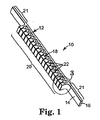
- a flexure 10 for use in a micro-electro-mechanical system (MEMS) is shown in Figures 1-3.
- the flexure 10 includes a compliant longitudinal beam 12 having a first side 14 and a second side 16 opposite first side 14.
- An actuator 18 is integrally formed with beam 12.
- the actuator 18 may be selectively activated to flex beam 12.
- flexure 10 may, for example, be positioned to interact with a movable mass (not shown), such that flexing of beam 12 by actuator 18 moves the moveable mass.
- actuator 18 is integrally formed as part of a central section 20 of beam 12. However, actuator 18 may be positioned along any portion of the length of beam 12 (such as adjacent an end 23 of beam 12), or along the entire length of beam 12, as is required for a particular application.
- the end sections 21 of beam 12 may be of any length appropriate for the flexures intended use.
- the dimensions of the embodiment of invention shown in Figures 1-3 should not be construed as limiting with regard to the dimensions and positioning of actuator 18.
- actuator 18 is of an electrostatic nature. That is, actuator 18 is selectively activated by the presence of an electrostatic charge.
- actuator 18 comprises a plurality of force elements 22 projecting from the first side 14 of beam 12. When flexure 10 is electrostatically charged, force elements 22 move apart from each other due to a repulsive electrostatic force and thereby flex beam 12 towards its second side 16.
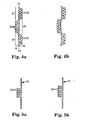
- Force elements 22 may also be positioned on both sides of beam 12. As shown in Figure 4a, force elements 22 are positioned adjacent both first side 14 and second side 16 of beam 12. The group of force elements 22 positioned on first side 14 in the central section 20 of beam 12 will act to flex end sections 21 of beam 12 toward second side 16. At the same time, the group of force elements 22 positioned on second side 16 in the end sections 21 of beam 12 will act to flex the ends 23 of beam 12 back toward first side 14. When electrostatically charged, beam 12 will have a shape similar to that shown in Figure 4b (the shape of beam 12 in Figure 4b is greatly exaggerated for illustrative purposes). Force elements 22 may be positioned along the beam 12 in configurations other than that shown which result in the desired shape of beam 12 when electrostatically charged.
- Force elements 22 also function to limit the bending or flexing of beam 12 toward the side of the beam 12 with force elements 22.
- force elements 22 limit the bending of beam 12 toward its first side 14.
- force elements 22 contact each other and thereby prevent further flexing or bending of beam 12 in that direction. In this manner, additional elements intended to limit the movement of beam 12 or a mass with which it interacts do not need to be incorporated in the MEMS device using flexure 10.
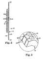
- beam 12 When used as a micro-electro-mechanical device, beam 12 may have a width between the first side 14 and second side 16 in the range of 100,000 angstroms (10 microns) or less, and more typically less than 30,000 angstroms (3 microns), depending upon the intended application of flexure 10. Beam 12 may also preferably be a high aspect ratio beam. In one possible embodiment, beam 12 will have an aspect ratio of at least 3, but the aspect ratio may be much more or less depending upon the application. A high aspect ratio in beam 12 creates more surface area between adjacent force elements 22, and thus creates a larger actuation force between adjacent force elements 22 when flexure 10 is electrostatically charged. The aspect ratio of beam 12 will be influenced by factors including the force required to be generated by actuator 18 of flexure 10, the strength of the electrostatic charge and the amount of available space in the MEMS device.
- force elements 22 comprise T-shaped (or hammer-shaped) elements which are monolithically attached to and extend from the first side 14 of beam 12.
- Each T-shaped element comprises a T-stem 24 and a T-cross member 26, with the T-stem 24 extending from beam 12.
- T-cross members 26 move apart from each other when electrostatically charged to flex beam 12 toward second side 16. T-cross members 26 will contact each other if beam 12 is flexed toward first side 14, and thereby limit the degree to which beam 12 can flex toward first side 14.
- Force elements 22 may have shapes other than a T-shape as illustrated in Figures 1-3.
- force elements 22 may be straight (Figure 5a), L-shaped ( Figure 5b), or any other shape which may used to create a repulsive force when electrostatically charged.
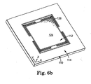
- FIGS 6a and 6b show one embodiment of a high-density storage module 110.
- Storage module 110 includes a rotor 112 and a frame 114 for supporting rotor 112.
- Rotor 112 is bounded by its top edge 116, bottom edge 118, left edge 120 and right edge 122.
- the front face 124 of rotor 112 defines an X-Y plane, with top edge 116 and bottom edge 118 aligned with the X-axis, and left edge 120 and right edge 122 aligned with the Y-axis.
- Front face 124 of rotor 112 is formed from a storage medium that has a plurality of storage areas 126 for data storage.
- the storage areas 126 (shown generically in Figure 6b) are in one of a plurality of states to represent data stored in that area.
- Rotor frame 114 is spaced from rotor edges 116, 118, 120 and 122. In one embodiment, rotor frame 114 surrounds rotor 112 in the X-Y plane.
- directional terms such as top, bottom, left, right, front and back are relative terms, and should not be construed as a limitation on the overall orientation of the storage module 110).
- Rotor 112 is supported within rotor frame 114 by a plurality of flexures 10 which interconnect rotor 112 and rotor frame 114.
- Force elements 22 of flexures 10 are not illustrated in Figures 6a and 6b for reasons of clarity.
- flexures 10 are of the type described above having integrally formed actuators 18.
- the flexures 10 supply both support of the rotor 112 and compliance for movements of rotor 112.
- this ratio can be limited by the chosen mechanical architecture.
- a high compliance ratio is desirable is that the forces provided by the actuator 18 integrally formed in flexures 10 are not very strong. Improving in-plane compliance while maintaining, or improving, the compliance ratio allows the relatively weak forces of integral actuators 18 to move rotor 112 in an acceptable manner. Increasing the in-plane compliance may be accomplished by allowing for axial shortening of the flexures 10. That is, as the flexures 10 bend they tend to become shorter in their axial direction which leads to a decrease in the in-plane compliance. Compensating for this axial shortening will increase the in-plane compliance.
- An additional way to improve the in-plane compliance while keeping the out-of-plane compliance low and still improving the compliance ratio is to allow the ends of the flexures 10 to move angularly. Even a small angle at either or both ends of the beam 12 can significantly increase the in-plane compliance. In many instances, the same structure may compensate for axial shortening and also allow angular movement of the beam.
- a first pair of coupling beams 130a, 130b extend from top edge 116 of the rotor 112, while a second pair of coupling beams 132a, 132b extend from bottom edge 118 of rotor 112.
- rotor 112 is rectangular in shape and first set of coupling beams 130a, 130b, 132a, 132b extend from the corners of rotor 112.
- Coupling beams 130a, 130b, 132a, 132b are generally aligned with the left and right edges 120, 122 of rotor 112.
- coupling beams 130a, 130b, 132a, 132b may have a different origination and orientation from that shown in Figures 6a and 6b.
- the alternate embodiments shown in Figures 7a and 7b allow coupling beam 130a additional freedom to rotate and thereby provide additional in-plane compliance to the rotor 112.
- First pair of coupling beams 30a, 30b are connected to first coupling mass 134a (positioned adjacent top edge 116 of rotor 112) by flexures 136a extending between the first pair of coupling beams 130a, 130b and first coupling mass 134a.
- Second pair of coupling beams 132a, 132b are connected to second coupling mass 134b (positioned adjacent bottom edge 118 of rotor 112) by flexures 136b extending between the second pair of coupling beams 132a, 132b and second coupling mass 134b.
- First set of flexures 136a, 136b have an axial orientation which is generally aligned with the top and bottom edges 116, 118 of rotor 112.
- Rotor frame 114 includes first and second flexure mounts 140a, 140b, which are positioned on opposite sides of rotor 112 (adjacent left edge 120 and right edge 122 as shown in Figure 6a).
- First and second coupling masses 134a, 134b are connected to first flexure mount 140a by flexures 142a.
- First and second coupling masses 134a, 134b are connected to second flexure mount 140b by flexures 142b.
- Second set of flexures 142a, 142b have an axial orientation which is generally aligned with the left and right edges 120, 122 of rotor 112.
- Coupling masses 134a, 134b simply act as rigid bodies to translate movement between flexures 142a, 142b and flexures 136a, 136b.
- the sets of flexures 136a, 136b, 142a, 142b each comprise a total of four individual flexures.
- a different number of individual flexures may be used in the sets of flexures (for example, a total of two or six flexures in each set).
- flexures 136a, 136b are in the X-Z plane; this set of flexures may be flexed in the Y direction allowing the rotor 112 to move in the Y direction with respect to the frame 114.
- the faces of flexures 142a, 142b are in the Y-Z direction; this set of flexures may be flexed in the X direction allowing the rotor 112 to move in the X direction with respect to the frame 114.
- FIG 8 shows end views of a high aspect ratio beam under no load (Position A), in-plane and out-of-plane loads (Position B), and in-plane, out-of-plane and torsion loads (Position C).
- the beams torsional and out-of-plane compliance is reduced by aligning the flexures 10 in such a way as to effectively counteract the torsions created in the flexures 10 as the rotor 112 is displaced along the Z-axis, such as by vibrational forces.
- the greatest counteraction effect is achieved when flexures 136a, 136b are oriented to axially point at the midpoint of flexures 142a, 142b.
- counteraction of the torsions are also achieved the lesser extent when the intersection is not at the midpoint of flexures 142a, 142b.
- the position of the first and second set of flexures 136a, 136b is such that the axis of the first and second set of flexures 136a, 136b, intersects the flexures 142a, 142b somewhere along the length of flexures 142a, 142b.
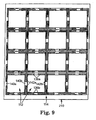
- FIG. 1 A storage module 210 having an array of rotors 112 is illustrated in Figure 9. It will be noted that the orientation of flexures 136a, 136b, 142a, 142b provides a significant benefit when a plurality of rotors 112 are used in the storage module 210.
- flexures 136a, 136b, 142a, 142b are arranged about the periphery of rotors 112 such that flexures 136a, 136b, 142a, 142b are each in substantially parallel alignment with the respective adjacent edges of rotors 112.
- the total area required for each rotor 112 and its associated suspension system is reduced and the packing density of rotors 112 within storage module 210 is correspondingly increased.
- the packing density of the rotors 112 in storage module 210 may be further increased, as illustrated in Figure 9, by eliminating the majority of the frame 114 between adjacent rotors 12. Specifically, it can be seen in Figure 9 that the frame 114 is reduced to leave only the flexure mounts 140a, 140b of adjacent rotors 112. That is, the only portion of frame 114 between adjacent rotors is the flexure mounts 140a, 140b.
- the flexure mounts are mechanically secured to a motion ground, so that each rotor of the array of rotors 112 may move independently.
- frame 114 may also be extended so that it fully surrounds each rotor, if that is desired.
Landscapes
- Engineering & Computer Science (AREA)
- Computer Hardware Design (AREA)
- Microelectronics & Electronic Packaging (AREA)
- Mechanical Engineering (AREA)
- Health & Medical Sciences (AREA)
- General Health & Medical Sciences (AREA)
- Toxicology (AREA)
- Micromachines (AREA)
Applications Claiming Priority (2)
| Application Number | Priority Date | Filing Date | Title |
|---|---|---|---|
| US124888 | 2002-04-18 | ||
| US10/124,888 US6798113B2 (en) | 2002-04-18 | 2002-04-18 | Flexure with integral electrostatic actuator |
Publications (3)
| Publication Number | Publication Date |
|---|---|
| EP1354849A2 EP1354849A2 (en) | 2003-10-22 |
| EP1354849A3 EP1354849A3 (en) | 2005-04-13 |
| EP1354849B1 true EP1354849B1 (en) | 2006-06-21 |
Family
ID=28674701
Family Applications (1)
| Application Number | Title | Priority Date | Filing Date |
|---|---|---|---|
| EP03252254A Expired - Lifetime EP1354849B1 (en) | 2002-04-18 | 2003-04-09 | Flexure with integral actuator |
Country Status (4)
| Country | Link |
|---|---|
| US (1) | US6798113B2 (enExample) |
| EP (1) | EP1354849B1 (enExample) |
| JP (1) | JP2004001198A (enExample) |
| DE (1) | DE60306243T2 (enExample) |
Families Citing this family (8)
| Publication number | Priority date | Publication date | Assignee | Title |
|---|---|---|---|---|
| US7177068B2 (en) * | 2002-12-20 | 2007-02-13 | Robert Bosch Gmbh | Apparatus, method and system for providing enhanced mechanical protection for thin beams |
| US7268463B2 (en) * | 2005-07-28 | 2007-09-11 | Freescale Semiconductor, Inc. | Stress release mechanism in MEMS device and method of making same |
| JP4724505B2 (ja) * | 2005-09-09 | 2011-07-13 | 株式会社日立製作所 | 超音波探触子およびその製造方法 |
| JP4525656B2 (ja) * | 2006-09-29 | 2010-08-18 | セイコーエプソン株式会社 | 印刷装置 |
| DE102016001414A1 (de) * | 2016-01-29 | 2017-08-03 | Sagross Designoffice Gmbh | Anordnung und Verfahren zur veränderbaren Verformung von Handhabungsgeräten, Werkzeugen und anderen mechanischen Konstruktionen |
| US10291151B2 (en) | 2016-04-19 | 2019-05-14 | Mems Start, Llc | Flexure shear and strain actuator |
| US10958885B2 (en) | 2016-08-26 | 2021-03-23 | Mems Start, Llc | Filtering imaging system including a light source to output an optical signal modulated with a code |
| US10368021B2 (en) | 2016-08-26 | 2019-07-30 | Mems Start, Llc | Systems and methods for derivative sensing using filtering pixels |
Family Cites Families (10)
| Publication number | Priority date | Publication date | Assignee | Title |
|---|---|---|---|---|
| US4374402A (en) * | 1980-06-27 | 1983-02-15 | Burroughs Corporation | Piezoelectric transducer mounting structure and associated techniques |
| JP3052469B2 (ja) * | 1991-09-12 | 2000-06-12 | 富士電機株式会社 | 静電アクチュエータ |
| US5355712A (en) * | 1991-09-13 | 1994-10-18 | Lucas Novasensor | Method and apparatus for thermally actuated self testing of silicon structures |
| US5179499A (en) * | 1992-04-14 | 1993-01-12 | Cornell Research Foundation, Inc. | Multi-dimensional precision micro-actuator |
| US5563446A (en) | 1994-01-25 | 1996-10-08 | Lsi Logic Corporation | Surface mount peripheral leaded and ball grid array package |
| US5920978A (en) * | 1995-03-01 | 1999-07-13 | Fujitsu Limited | Method of making a thin film magnetic slider |
| JPH10109284A (ja) * | 1996-10-03 | 1998-04-28 | Denso Corp | マイクロマニピュレータとその駆動方法 |
| KR100287567B1 (ko) * | 1996-10-31 | 2001-04-16 | 사토 히로시 | 판독/기록헤드,판독/기록헤드위치선정기구,및판독/기록시스템 |
| US5959516A (en) * | 1998-01-08 | 1999-09-28 | Rockwell Science Center, Llc | Tunable-trimmable micro electro mechanical system (MEMS) capacitor |
| US6307298B1 (en) * | 2000-03-20 | 2001-10-23 | Motorola, Inc. | Actuator and method of manufacture |
-
2002
- 2002-04-18 US US10/124,888 patent/US6798113B2/en not_active Expired - Fee Related
-
2003
- 2003-04-03 JP JP2003100063A patent/JP2004001198A/ja active Pending
- 2003-04-09 EP EP03252254A patent/EP1354849B1/en not_active Expired - Lifetime
- 2003-04-09 DE DE60306243T patent/DE60306243T2/de not_active Expired - Lifetime
Also Published As
| Publication number | Publication date |
|---|---|
| DE60306243D1 (de) | 2006-08-03 |
| EP1354849A3 (en) | 2005-04-13 |
| US6798113B2 (en) | 2004-09-28 |
| DE60306243T2 (de) | 2007-03-08 |
| US20030197445A1 (en) | 2003-10-23 |
| EP1354849A2 (en) | 2003-10-22 |
| JP2004001198A (ja) | 2004-01-08 |
Similar Documents
| Publication | Publication Date | Title |
|---|---|---|
| US6812617B2 (en) | MEMS device having a flexure with integral electrostatic actuator | |
| EP1130442B1 (en) | Optical switches using dual axis micromirrors | |
| US7055975B2 (en) | Microelectromechanical system with non-collinear force compensation | |
| EP1419396B1 (en) | Arcuately shaped flexures for micro-machined electromechanical system (mems) accelerometer device | |
| JP5330309B2 (ja) | ジンバル付きmemsミラー・ヒンジ用折り返し縦トーション・ヒンジ | |
| US20160315560A1 (en) | In-plane and out-of-plane motion actuator | |
| US20080157627A1 (en) | Electrostatic actuator with interdigitated electrode structure | |
| US6698201B1 (en) | Cascaded bimorph rotary actuator | |
| US20030173865A1 (en) | Microelectromechanical system with stiff coupling | |
| EP1508142B1 (en) | A movable micro-electromechanical device | |
| EP1330672A2 (en) | Gimbaled micro-mirror positionable by thermal actuators | |
| US6384510B1 (en) | Electrostatic microactuator with offset and/or inclined comb drive fingers | |
| EP1354849B1 (en) | Flexure with integral actuator | |
| EP2419370A2 (en) | Long travel range mems actuator | |
| CN112368232B (zh) | 包括可移动结构元件的mems和mems阵列 | |
| EP1223664A2 (en) | Actuator with a flexure arrangement to accomodate a long range of motion | |
| US6543087B2 (en) | Micro-electromechanical hinged flap structure | |
| US6954348B1 (en) | Tunable MEMS capacitor | |
| JP7235095B2 (ja) | 低衝撃モーションリミッタ | |
| EP1228391A2 (en) | Mechanically latching optical switch | |
| US6665104B2 (en) | Mirror positioning assembly with vertical force component compensation | |
| US6791234B2 (en) | Micromechanical rotation system with coupled actuators | |
| JP4396299B2 (ja) | ミラーシステム及び光スイッチ | |
| US6356418B1 (en) | Silicon structural support of linear microactuator | |
| WO2000062410A1 (en) | Electrostatic microactuator with offset and/or inclined comb drive fingers |
Legal Events
| Date | Code | Title | Description |
|---|---|---|---|
| PUAI | Public reference made under article 153(3) epc to a published international application that has entered the european phase |
Free format text: ORIGINAL CODE: 0009012 |
|
| AK | Designated contracting states |
Kind code of ref document: A2 Designated state(s): AT BE BG CH CY CZ DE DK EE ES FI FR GB GR HU IE IT LI LU MC NL PT RO SE SI SK TR |
|
| AX | Request for extension of the european patent |
Extension state: AL LT LV MK |
|
| PUAL | Search report despatched |
Free format text: ORIGINAL CODE: 0009013 |
|
| AK | Designated contracting states |
Kind code of ref document: A3 Designated state(s): AT BE BG CH CY CZ DE DK EE ES FI FR GB GR HU IE IT LI LU MC NL PT RO SE SI SK TR |
|
| AX | Request for extension of the european patent |
Extension state: AL LT LV MK |
|
| 17P | Request for examination filed |
Effective date: 20050627 |
|
| GRAP | Despatch of communication of intention to grant a patent |
Free format text: ORIGINAL CODE: EPIDOSNIGR1 |
|
| AKX | Designation fees paid |
Designated state(s): DE GB IT |
|
| GRAS | Grant fee paid |
Free format text: ORIGINAL CODE: EPIDOSNIGR3 |
|
| GRAA | (expected) grant |
Free format text: ORIGINAL CODE: 0009210 |
|
| AK | Designated contracting states |
Kind code of ref document: B1 Designated state(s): DE GB IT |
|
| PG25 | Lapsed in a contracting state [announced via postgrant information from national office to epo] |
Ref country code: IT Free format text: LAPSE BECAUSE OF FAILURE TO SUBMIT A TRANSLATION OF THE DESCRIPTION OR TO PAY THE FEE WITHIN THE PRESCRIBED TIME-LIMIT;WARNING: LAPSES OF ITALIAN PATENTS WITH EFFECTIVE DATE BEFORE 2007 MAY HAVE OCCURRED AT ANY TIME BEFORE 2007. THE CORRECT EFFECTIVE DATE MAY BE DIFFERENT FROM THE ONE RECORDED. Effective date: 20060621 |
|
| REG | Reference to a national code |
Ref country code: GB Ref legal event code: FG4D |
|
| REF | Corresponds to: |
Ref document number: 60306243 Country of ref document: DE Date of ref document: 20060803 Kind code of ref document: P |
|
| PLBE | No opposition filed within time limit |
Free format text: ORIGINAL CODE: 0009261 |
|
| STAA | Information on the status of an ep patent application or granted ep patent |
Free format text: STATUS: NO OPPOSITION FILED WITHIN TIME LIMIT |
|
| 26N | No opposition filed |
Effective date: 20070322 |
|
| PGFP | Annual fee paid to national office [announced via postgrant information from national office to epo] |
Ref country code: DE Payment date: 20110427 Year of fee payment: 9 |
|
| PGFP | Annual fee paid to national office [announced via postgrant information from national office to epo] |
Ref country code: GB Payment date: 20110426 Year of fee payment: 9 |
|
| REG | Reference to a national code |
Ref country code: GB Ref legal event code: 732E Free format text: REGISTERED BETWEEN 20120329 AND 20120404 |
|
| PGFP | Annual fee paid to national office [announced via postgrant information from national office to epo] |
Ref country code: IT Payment date: 20120423 Year of fee payment: 10 |
|
| GBPC | Gb: european patent ceased through non-payment of renewal fee |
Effective date: 20120409 |
|
| PG25 | Lapsed in a contracting state [announced via postgrant information from national office to epo] |
Ref country code: GB Free format text: LAPSE BECAUSE OF NON-PAYMENT OF DUE FEES Effective date: 20120409 |
|
| REG | Reference to a national code |
Ref country code: DE Ref legal event code: R119 Ref document number: 60306243 Country of ref document: DE Effective date: 20121101 |
|
| PG25 | Lapsed in a contracting state [announced via postgrant information from national office to epo] |
Ref country code: IT Free format text: LAPSE BECAUSE OF NON-PAYMENT OF DUE FEES Effective date: 20130409 |
|
| PG25 | Lapsed in a contracting state [announced via postgrant information from national office to epo] |
Ref country code: DE Free format text: LAPSE BECAUSE OF NON-PAYMENT OF DUE FEES Effective date: 20121101 |