EP1354615A1 - Filtereinrichtung mit einem Filterkörper und Verfahren zu dessen Reinigung - Google Patents
Filtereinrichtung mit einem Filterkörper und Verfahren zu dessen Reinigung Download PDFInfo
- Publication number
- EP1354615A1 EP1354615A1 EP03006433A EP03006433A EP1354615A1 EP 1354615 A1 EP1354615 A1 EP 1354615A1 EP 03006433 A EP03006433 A EP 03006433A EP 03006433 A EP03006433 A EP 03006433A EP 1354615 A1 EP1354615 A1 EP 1354615A1
- Authority
- EP
- European Patent Office
- Prior art keywords
- filter
- liquid
- container
- filter body
- outflow side
- Prior art date
- Legal status (The legal status is an assumption and is not a legal conclusion. Google has not performed a legal analysis and makes no representation as to the accuracy of the status listed.)
- Ceased
Links
- 238000000034 method Methods 0.000 title claims abstract description 37
- 238000001914 filtration Methods 0.000 title claims abstract description 5
- 238000004140 cleaning Methods 0.000 title claims description 27
- 239000007788 liquid Substances 0.000 claims abstract description 72
- 238000009423 ventilation Methods 0.000 claims description 5
- 230000015572 biosynthetic process Effects 0.000 claims 1
- 239000007789 gas Substances 0.000 description 16
- 238000011001 backwashing Methods 0.000 description 11
- 238000011010 flushing procedure Methods 0.000 description 7
- 239000000463 material Substances 0.000 description 6
- 230000000694 effects Effects 0.000 description 5
- 239000002245 particle Substances 0.000 description 5
- 238000010586 diagram Methods 0.000 description 3
- 238000013022 venting Methods 0.000 description 3
- 238000007796 conventional method Methods 0.000 description 2
- 239000012530 fluid Substances 0.000 description 2
- 239000007787 solid Substances 0.000 description 2
- 239000002699 waste material Substances 0.000 description 2
- XLYOFNOQVPJJNP-UHFFFAOYSA-N water Substances O XLYOFNOQVPJJNP-UHFFFAOYSA-N 0.000 description 2
- 238000009825 accumulation Methods 0.000 description 1
- 238000005276 aerator Methods 0.000 description 1
- 238000011109 contamination Methods 0.000 description 1
- 230000001419 dependent effect Effects 0.000 description 1
- 239000011261 inert gas Substances 0.000 description 1
- 238000003825 pressing Methods 0.000 description 1
- 238000000926 separation method Methods 0.000 description 1
Images


Classifications
-
- B—PERFORMING OPERATIONS; TRANSPORTING
- B01—PHYSICAL OR CHEMICAL PROCESSES OR APPARATUS IN GENERAL
- B01D—SEPARATION
- B01D29/00—Filters with filtering elements stationary during filtration, e.g. pressure or suction filters, not covered by groups B01D24/00 - B01D27/00; Filtering elements therefor
- B01D29/01—Filters with filtering elements stationary during filtration, e.g. pressure or suction filters, not covered by groups B01D24/00 - B01D27/00; Filtering elements therefor with flat filtering elements
-
- B—PERFORMING OPERATIONS; TRANSPORTING
- B01—PHYSICAL OR CHEMICAL PROCESSES OR APPARATUS IN GENERAL
- B01D—SEPARATION
- B01D29/00—Filters with filtering elements stationary during filtration, e.g. pressure or suction filters, not covered by groups B01D24/00 - B01D27/00; Filtering elements therefor
- B01D29/11—Filters with filtering elements stationary during filtration, e.g. pressure or suction filters, not covered by groups B01D24/00 - B01D27/00; Filtering elements therefor with bag, cage, hose, tube, sleeve or like filtering elements
- B01D29/13—Supported filter elements
- B01D29/15—Supported filter elements arranged for inward flow filtration
-
- B—PERFORMING OPERATIONS; TRANSPORTING
- B01—PHYSICAL OR CHEMICAL PROCESSES OR APPARATUS IN GENERAL
- B01D—SEPARATION
- B01D29/00—Filters with filtering elements stationary during filtration, e.g. pressure or suction filters, not covered by groups B01D24/00 - B01D27/00; Filtering elements therefor
- B01D29/50—Filters with filtering elements stationary during filtration, e.g. pressure or suction filters, not covered by groups B01D24/00 - B01D27/00; Filtering elements therefor with multiple filtering elements, characterised by their mutual disposition
- B01D29/52—Filters with filtering elements stationary during filtration, e.g. pressure or suction filters, not covered by groups B01D24/00 - B01D27/00; Filtering elements therefor with multiple filtering elements, characterised by their mutual disposition in parallel connection
-
- B—PERFORMING OPERATIONS; TRANSPORTING
- B01—PHYSICAL OR CHEMICAL PROCESSES OR APPARATUS IN GENERAL
- B01D—SEPARATION
- B01D29/00—Filters with filtering elements stationary during filtration, e.g. pressure or suction filters, not covered by groups B01D24/00 - B01D27/00; Filtering elements therefor
- B01D29/62—Regenerating the filter material in the filter
- B01D29/66—Regenerating the filter material in the filter by flushing, e.g. counter-current air-bumps
-
- B—PERFORMING OPERATIONS; TRANSPORTING
- B01—PHYSICAL OR CHEMICAL PROCESSES OR APPARATUS IN GENERAL
- B01D—SEPARATION
- B01D2201/00—Details relating to filtering apparatus
- B01D2201/04—Supports for the filtering elements
- B01D2201/043—Filter tubes connected to plates
- B01D2201/0446—Filter tubes connected to plates suspended from plates at the upper side of the filter elements
Definitions
- the invention relates to a filter device with a filter body for filtering a Liquid, as well as a method for cleaning it.
- a filter body designed as a filter candle is, for example, from DE 34 07 433 A1 known.
- the liquid to be filtered for example water
- the filter candle is in usually depending on the contamination of the liquid to be filtered Particles to be separated repeatedly cleaned.
- a compressed air cushion in the container on the clean liquid side created while most of the container, especially the whole Raw liquid side into which the filter candles protrude remains liquid-filled. With With the help of the compressed air, liquid is now passed through the filter candles from the clean liquid side pressed onto the raw liquid side.
- the compressed air supply is turned on interrupted on the clean liquid side and then using the in the container existing compressed air cushion of the filter body backwashed. For backwashing a valve on the raw liquid side opened as suddenly as possible. With This common method, however, is only a part of that in the filter cartridges captured particles loosened and washed onto the clean liquid side. Because of this only limited cleaning effect with such The rinsing process results in the operating cycle following the rinsing process faster increase in differential pressure between raw liquid and Pure liquid side than in the operating cycle before the rinsing process.
- the invention has for its object a filter device with a filter body and to specify a method for cleaning it, which is a particular enable long filter service life.
- the pressure on the outflow side increases.
- the liquid thus flows from the outflow side through the filter body onto the air-filled inflow side.
- compressed air for backwashing and air for The inflow side can be ventilated, particularly depending on the one to be filtered Liquid, another suitable gas, for example an inert gas become.
- compressed air is general in the following as “compressed gas”
- ventilation and “venting” as “filling with a Gas “or” emptying a gas "to understand.
- the invention is based on the consideration that the cleaning effect when Rinsing a filter body is the better, the greater the pressure difference at the filter body is.
- conventional rinsing of a filter with liquid it spreads out the pressure loss of the liquid over the entire flow path from the outflow to the inflow side. Only part of this pressure loss occurs on the filter body directly on, while for example supply and discharge lines as well as other components contribute significantly to pressure loss.
- the inertia of the liquid also plays an important role by means of compressed air Role.
- the flow rate of the liquid flowing through the filter body is due to the mass and volume of the total during the rinsing process displacing liquid. In particular builds up during the rinsing process a back pressure in the liquid on the inflow side of the filter body on the pressure gradient used for filter cleaning between the outflow and Counteracts the inflow side of the filter body.
- the filter rinsing pressure on the outflow side of the filter body is fully used for filter cleaning.
- On the inflow side of the filter body is at the beginning of the rinsing process first air under atmospheric pressure, so that when flushing the liquid pressed from the outflow side through the filter body on the Inflow side can spread freely.
- a slight fluid leakage between The outflow and inflow sides before the start of the flushing process are insignificant, as far as the inflow side is essentially air-filled.
- the liquid pressure on the outflow side on the limited by the weight of the liquid pressure is an unintentional flow through the filter body from the Outflow to the inflow side before the start of the flushing process, at least to an insignificant extent Dimension reduced.
- the slight overpressure of the liquid on the Outflow side of the filter body can be by a above the filter body in the Container arranged liquid column or for example by a liquid column generated in a line connected to the outflow side of the container his.
- the container is preferably essentially from below flows upwards and in backwashing mode from top to bottom.
- the pressure increase causing the flushing process takes place on the outflow side preferably pulse-like, preferably by a compressed air pulse. Due to the impulsive Applying pressure can achieve a better cleaning effect than in In the case of a uniform liquid flow with a relatively low flow rate.
- the effectiveness of introducing a pulse of compressed air into the liquid is particularly high if there is no air cushion on the outflow side of the Container was present, as such would dampen the compressed air pulse. It is particularly important for a good cleaning effect in backwashing a steep increase in the compressed air pulse.
- the duration of the compressed air pulse can especially depending on the maximum mass flow through the filter body and the liquid and gas volumes in the container can be varied.
- the object is achieved according to the invention by a Filter device with the features of claim 5.
- Preferred embodiments and further training are the subject of referring back to this Dependent claims.
- the advantages mentioned in connection with the procedure are accordingly also transferable to the device.
- a filter unit 1 shows a filter unit 1 with a filter body arranged in a container 2 3.
- a liquid F flows from an inflow side during filter operation 4 through the filter body 3 to an outflow side 5.
- the liquid F becomes fed to the container 2 via an inlet line 6 and through an outlet line 7 dissipated from this.
- a ventilation device is located on the container 2 on the inflow side 4 8 and an emptying device 9 are provided.
- On the outflow side 5 of the container 2, a compressed gas connection 10 is provided on the outflow side 5 of the container 2, a compressed gas connection 10 is provided.
- the inflow side 4 is also used as the raw liquid side, the outflow side 5 as Clean liquid side designated.
- the ventilation device 8, the emptying device 9 and the compressed gas connection 10 each have a shut-off valve 8a, 9a, 10a.
- the drain line 7 conducts the filtered liquid F vertically further up to an apparatus, not shown, within a closed Liquid circuit.
- the filter body 3 Before cleaning or backwashing the filter body 3 is first on the Inflow side 4 of the container 2 liquid F with the help of the emptying device 9 and the ventilation device 8 emptied. After emptying the ventilation device 8 is closed again.
- the liquid F on the outflow side 5 remains in the container 2.
- the liquid level in the Drain line 7 is so high that the liquid F with a slight overpressure is pressed against the outflow side 5 of the filter body 3.
- Not one Shut-off valve shown in the drain line 7 is closed. Between this shut-off valve and the outflow surface of the filter body 3 no gas cushion is formed in the entire outflow region of the container 2.
- the liquid F is then on the outflow side 5 via the compressed gas connection 10 with a compressed gas pulse, in particular compressed air pulse.
- the emptying device 9 is open here. Because the inflow side 4 of the container 2 exclusively or predominantly with atmospheric air is filled, practically the entire falls due to the compressed gas pulse in the Liquid F spreading on the outflow side 5 overpressure directly on the filter body 3 from.
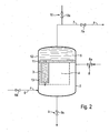
- Fig. 2 shows a filter device 1 with a filter cartridge 3 as a filter body.
- a single filter candle designed as a folded candle 3 is shown.
- the Folding candle 3 has an essentially cylindrical basic shape, with a flat one Filter material, for example a plastic or paper fleece for the separation of particles from the liquid F is used.
- the flat filter material is - in plan view on the filter candle - folded approximately in a star shape and into an annular space in the Filter candle embedded.
- To support the flat filter material is a Support structure provided, the two coaxial liquid-permeable jacket walls forms between which the filter material is enclosed in the annular space.
- the container 2 contains a large number, for example approximately 300, of such folding candles 3.
- the folding or filter candles 3 are hanging in a cross section of the container 2 filling holding plate 11 held.
- In the holding plate 11 is for each filter candle 3 each have an opening.
- Each filter candle 3 is on the top, on the holding plate 11, open and closed on the underside.
- the too filtering liquid F flows through the filter candles 3 from the outside inwards.
- the Part of the container 2 formed as a filter dome 12 above the holding plate 11 forms the clean liquid side or together with the interior of the folding candles 3 Outflow side 5.
- the part of the container arranged below the holding plate 11 2 forms - outside the filter material of the plugs 3 - the raw liquid side or inflow side 4.
- the liquid F is the container 2 on the inflow side 4 supplied laterally via a shut-off valve 6a and flows through the container 2 in filter mode essentially from bottom to top.
- the folding candles 3 filled with liquid F, in particular water. Because of the low fluid pressure, the fine-pored, especially microporous training the filter candles 3, and the accumulation of particles on the filter candles 3 practically no liquid F flows out of the before the rinsing process Filter candles 3 back into the ventilated inflow side 4. In addition, before the start of the Rinsing a shut-off valve 7a in the drain line 7 closed.
- the folding candles 3 are in addition to their holder on their respective top by the holding plate 11 fixed on the underside thereof by a holding grid 13.
- the emptying device 9 To empty the contaminated liquid F after the rinsing process is the emptying device 9 provided.
- the compressed air used for backwashing the plugs 3 is available with an overpressure of 6 bar, for example.
- the filter dome 12 Before the Backwashing is the filter dome 12 including the drain line 7 to the shut-off valve 7a free of gas bubbles.
- the shut-off valve 10a becomes the introduction of compressed air opened as quickly as possible during the flushing process. Since in the filter dome 12 initially there is no gas cushion, a pressure pulse spreads with a steep rise in the liquid F, in particular also in the liquid-filled filter candles 3 in, out quickly. The dirt adhering to and in the filter candles 3 are blown off very effectively.
- Fig. 3 shows in a diagram the dependence of the differential pressure dP between the pressure of the liquid F on the outflow side 5 of the filter body 3 in Fig. 2 shown filter device 1 and the pressure on the inflow side 4 of the Filter body 3 on the operating time.
- the operating time is divided into operating cycles.
- the solid, sawtooth-shaped line describes the differential pressure dP in filter mode, with the filter body 3 after each operating cycle the cleaning or rinsing process according to the invention is regenerated.
- To the Comparison is the time course of the differential pressure rise dP during cleaning filter unit 1 is drawn into the diagram by a conventional method (Just as an approximation). The conventional filter cleaning process is only used after every third operating cycle.
- the differential pressure dP increases continuously during filter operation. To Flushing or backflushing occurs when the first operating cycle ends a certain differential pressure dP of the filter unit 1 instead.
- an increase in the differential pressure dP can also be determined in the second operating cycle, which is however faster than the increase in the first operating cycle. Also at Further operating cycles will result in a faster increase in the differential pressure dP as determined in the previous operating cycle.
- the Differential pressure dP always approximately on the immediately after backwashing same level as with the new filter body 3 at the beginning of the first operating cycle.
Landscapes
- Chemical & Material Sciences (AREA)
- Chemical Kinetics & Catalysis (AREA)
- Filtering Of Dispersed Particles In Gases (AREA)
Abstract
Description
- Fig. 1
- eine Prinzipdarstellung einer Filtereinrichtung,
- Fig. 2
- eine Filtereinrichtung mit Filterkerze, und
- Fig. 3
- die Differenzdruck-Zeit-Abhängigkeit beim erfindungsgemäßen Verfahren sowie bei einem Verfahren zur Filterreinigung nach dem Stand der Technik.
- 1
- Filtereinheit
- 2
- Behälter
- 3
- Filterkörper
- 4
- Einströmseite
- 5
- Ausströmseite
- 6
- Zulaufleitung
- 6a
- Absperrarmatur
- 7
- Ablaufleitung
- 7a
- Absperrarmatur
- 8
- Belüftungseinrichtung
- 8a
- Absperrarmatur
- 9
- Entleerungseinrichtung
- 9a
- Absperrarmatur
- 10
- Druckgasanschluss
- 10a
- Absperrarmatur
- 11
- Halteplatte
- 12
- Filterdom
- 13
- Haltegitter
- dP
- Differenzdruck
- F
- Flüssigkeit
Claims (8)
- Verfahren zum Reinigen eines Filterkörpers (3) zum Filtern einer Flüssigkeit (F), der in einem Behälter (2) eine Einströmseite (4) von einer Ausströmseite (5) trennt, mit folgenden Schritten:Die Zufuhr der Flüssigkeit (F) auf der Einströmseite (4) wird unterbrochen,die Einströmseite (4) des Behälters (2) wird entleert und belüftet, wobei die Ausströmseite (5) mit Flüssigkeit (F) gefüllt bleibt,der Druck auf der Ausströmseite (5) wird erhöht, so dass Flüssigkeit (F) von der Ausströmseite (5) durch den Filterkörper (3) in die zunächst gasgefüllte Einströmseite (4) strömt.
- Verfahren nach Anspruch 1,
dadurch gekennzeichnet, dass der Druck auf der Ausströmseite (5) vor der Druckerhöhung ausschließlich durch die Gewichtskraft der auf der Ausströmseite (5) anstehenden Flüssigkeit (F) erzeugt wird. - Verfahren nach Anspruch 1 oder 2,
dadurch gekennzeichnet, dass die Druckerhöhung auf der Ausströmseite (5) impulsartig erfolgt. - Verfahren nach Anspruch 3,
dadurch gekennzeichnet, dass die Druckerhöhung auf der Ausströmseite (5) durch einen Druckluftimpuls erfolgt. - Filtereinrichtung zur Durchführung des Verfahrens nach einem der Ansprüche 1 bis 4 miteinem Behälter (2), in dem ein Filterkörper (3) eine Einströmseite (4) mit einer Zulaufleitung (6) von einer Ausströmseite (5) mit einer Ablaufleitung (7) trennt,einer Entleerungsvorrichtung (9) auf der Einströmseite (4),einer Belüftungsvorrichtung (8) auf der Einströmseite (4),einem Druckgasanschluss (10) auf der Ausströmseite (5).
- Filtereinrichtung nach Anspruch 5,
gekennzeichnet durch
eine mikroporöse Ausbildung des Filterkörpers (3). - Filtereinrichtung nach Anspruch 5 oder 6,
gekennzeichnet durch
eine Filterkerze (3) als Filterkörper. - Filtereinrichtung nach einem der Ansprüche 5 bis 7,
dadurch gekennzeichnet, dass die Filterkerze (3) hängend im Behälter (2) angeordnet ist.
Applications Claiming Priority (2)
| Application Number | Priority Date | Filing Date | Title |
|---|---|---|---|
| DE10215575 | 2002-04-10 | ||
| DE10215575A DE10215575A1 (de) | 2002-04-10 | 2002-04-10 | Filtereinrichtung mit einem Filterkörper und Verfahren zu dessen Reinigung |
Publications (1)
| Publication Number | Publication Date |
|---|---|
| EP1354615A1 true EP1354615A1 (de) | 2003-10-22 |
Family
ID=28458668
Family Applications (1)
| Application Number | Title | Priority Date | Filing Date |
|---|---|---|---|
| EP03006433A Ceased EP1354615A1 (de) | 2002-04-10 | 2003-03-21 | Filtereinrichtung mit einem Filterkörper und Verfahren zu dessen Reinigung |
Country Status (2)
| Country | Link |
|---|---|
| EP (1) | EP1354615A1 (de) |
| DE (1) | DE10215575A1 (de) |
Citations (3)
| Publication number | Priority date | Publication date | Assignee | Title |
|---|---|---|---|---|
| DE2310038A1 (de) * | 1972-08-21 | 1974-03-14 | Hydromation Filter Co | Verfahren und anordnung zum reinigen von filterelementen |
| US5017241A (en) * | 1990-10-16 | 1991-05-21 | The Graver Company | Backwash method and apparatus |
| US5494591A (en) * | 1992-07-30 | 1996-02-27 | Christ Ag | Cleaning of deposit filters |
Family Cites Families (1)
| Publication number | Priority date | Publication date | Assignee | Title |
|---|---|---|---|---|
| DE3407433A1 (de) * | 1984-02-29 | 1985-08-29 | Kraftwerk Union AG, 4330 Mülheim | Filterkerze |
-
2002
- 2002-04-10 DE DE10215575A patent/DE10215575A1/de not_active Ceased
-
2003
- 2003-03-21 EP EP03006433A patent/EP1354615A1/de not_active Ceased
Patent Citations (3)
| Publication number | Priority date | Publication date | Assignee | Title |
|---|---|---|---|---|
| DE2310038A1 (de) * | 1972-08-21 | 1974-03-14 | Hydromation Filter Co | Verfahren und anordnung zum reinigen von filterelementen |
| US5017241A (en) * | 1990-10-16 | 1991-05-21 | The Graver Company | Backwash method and apparatus |
| US5494591A (en) * | 1992-07-30 | 1996-02-27 | Christ Ag | Cleaning of deposit filters |
Also Published As
| Publication number | Publication date |
|---|---|
| DE10215575A1 (de) | 2003-10-30 |
Similar Documents
| Publication | Publication Date | Title |
|---|---|---|
| DE3117712A1 (de) | Verfahren und vorrichtung zur druckfilterung eines filtrates | |
| DE2036830A1 (de) | Filtrationssystem und Filtrationsver fahren | |
| EP0581740A2 (de) | Reinigung von Anschwemmfiltern | |
| EP0330747B1 (de) | Vorrichtung zum Zerlegen von Kondensat | |
| DE10340366B4 (de) | Filtervorrichtung | |
| CH672602A5 (de) | ||
| DE10108957A1 (de) | Verfahren und Vorrichtung zum Filtrieren von Flüssigkeiten, insbesondere Getränken | |
| EP0155336A1 (de) | Filterkerze | |
| CH634757A5 (de) | Verfahren und vorrichtung zur abscheidung von schwebstoffen aus suspensionen durch absitz- und filterverfahren. | |
| DE2310038A1 (de) | Verfahren und anordnung zum reinigen von filterelementen | |
| DE102005033314B4 (de) | Verfahren und Filteranlage zum Filtern von Rohwasser | |
| DE102007049658A1 (de) | Filter | |
| EP3378554B1 (de) | Modulfuss, vorrichtung und verfahren zum filtern eines eine verschmutzung enthaltenden rohfluids mittels mindestens einer membranfiltereinheit sowie eine verwendung hierzu | |
| EP1250948B1 (de) | Anschwemmfilter | |
| DE3542449C1 (en) | Apparatus and method for filtering liquids | |
| EP1258276B1 (de) | Verfahren und Einrichtung zur Filtration von Fluiden, die in Bearbeitungsmaschinen anfallen | |
| DE3145667A1 (de) | Verfahren und vorrichtung zur kompressionsregenerierung flexibler filter-, oelabscheide- und/oder traegermaterialien | |
| DE2215171A1 (de) | Verfahren bei Filtrierung, besonders von Öl, wie Feuerungsöl und Schmieröl, und Vorrichtung zur Ausübung des Verfahrens | |
| DE10215575A1 (de) | Filtereinrichtung mit einem Filterkörper und Verfahren zu dessen Reinigung | |
| EP1000648B1 (de) | Kerzenfilter und Verfahren zur Stabilisierung von Getränken sowie zum Regenerieren von Stabilisiermitteln | |
| DE3722238C2 (de) | ||
| DE3335127A1 (de) | Verfahren zur abtrennung von quecksilber aus waessrigen fluessigkeiten | |
| EP3338877B1 (de) | Verfahren und vorrichtung zum filtern eines eine verschmutzung enthaltenden rohfluids mittels mindestens einer membranfiltereinheit sowie eine verwendung hierzu | |
| EP3159314B1 (de) | Nachkläreinheit, verfahren und verwendung | |
| DE2601732B2 (de) | Verfahren zum Spulen der Filterkammern eines Filteraggregates und Filteraggregat zur Durchführung dieses Verfahrens |
Legal Events
| Date | Code | Title | Description |
|---|---|---|---|
| PUAI | Public reference made under article 153(3) epc to a published international application that has entered the european phase |
Free format text: ORIGINAL CODE: 0009012 |
|
| AK | Designated contracting states |
Kind code of ref document: A1 Designated state(s): AT BE BG CH CY CZ DE DK EE ES FI FR GB GR HU IE IT LI LU MC NL PT SE SI SK TR |
|
| AX | Request for extension of the european patent |
Extension state: AL LT LV MK RO |
|
| 17P | Request for examination filed |
Effective date: 20040209 |
|
| AKX | Designation fees paid |
Designated state(s): DE ES FI SE |
|
| 17Q | First examination report despatched |
Effective date: 20071213 |
|
| RAP1 | Party data changed (applicant data changed or rights of an application transferred) |
Owner name: AREVA NP GMBH |
|
| RAP1 | Party data changed (applicant data changed or rights of an application transferred) |
Owner name: AREVA NP GMBH |
|
| STAA | Information on the status of an ep patent application or granted ep patent |
Free format text: STATUS: THE APPLICATION HAS BEEN REFUSED |
|
| 18R | Application refused |
Effective date: 20091221 |