EP1353207B1 - Telecentric singlet having a small height requirement - Google Patents
Telecentric singlet having a small height requirement Download PDFInfo
- Publication number
- EP1353207B1 EP1353207B1 EP02023492A EP02023492A EP1353207B1 EP 1353207 B1 EP1353207 B1 EP 1353207B1 EP 02023492 A EP02023492 A EP 02023492A EP 02023492 A EP02023492 A EP 02023492A EP 1353207 B1 EP1353207 B1 EP 1353207B1
- Authority
- EP
- European Patent Office
- Prior art keywords
- lens
- diffractive
- singlet
- single lens
- lens system
- Prior art date
- Legal status (The legal status is an assumption and is not a legal conclusion. Google has not performed a legal analysis and makes no representation as to the accuracy of the status listed.)
- Expired - Lifetime
Links
Images


Classifications
-
- G—PHYSICS
- G02—OPTICS
- G02B—OPTICAL ELEMENTS, SYSTEMS OR APPARATUS
- G02B13/00—Optical objectives specially designed for the purposes specified below
- G02B13/001—Miniaturised objectives for electronic devices, e.g. portable telephones, webcams, PDAs, small digital cameras
- G02B13/0015—Miniaturised objectives for electronic devices, e.g. portable telephones, webcams, PDAs, small digital cameras characterised by the lens design
- G02B13/002—Miniaturised objectives for electronic devices, e.g. portable telephones, webcams, PDAs, small digital cameras characterised by the lens design having at least one aspherical surface
- G02B13/0025—Miniaturised objectives for electronic devices, e.g. portable telephones, webcams, PDAs, small digital cameras characterised by the lens design having at least one aspherical surface having one lens only
-
- G—PHYSICS
- G02—OPTICS
- G02B—OPTICAL ELEMENTS, SYSTEMS OR APPARATUS
- G02B13/00—Optical objectives specially designed for the purposes specified below
- G02B13/22—Telecentric objectives or lens systems
Definitions
- the present invention relates to optics, and more specifically, to a telecentric singlet having a small height requirement that is especially suited for space critical applications.
- a lens design typically utilizes more than two separate lenses in the lens design. For example, a first lens can be utilized for color separation functions, while a second lens can be utilized for ray bending functions.
- a diffractive surface for performing color correction functions.
- One challenge of using a diffractive surface is to design the surface in such a way as to increase the diffraction efficiency.
- the diffraction efficiency is related to how well the lens places light on the focal plane at desired locations. For example, a very efficient lens converges the incident light rays at discrete points (known as spots) along the focal plane. As the diffraction efficiency of the lens decreases, the size of the spots increases. As the spot size increase, the resulting image loses clarity and become fuzzier.
- Another challenge in single lens design is that the image exhibits vignetting (or shadowing) of the corners of the image. Accordingly, it is desirable for the single lens design to have a mechanism that reduces the amount of vignetting (or shadowing) of the corners of the image.
- the lens includes a first surface for performing color correction functions and a second surface for primarily performing light ray bending functions.
- the first surface has diffraction efficiency improvement mechanism for improving the resolution of the lens.
- the present invention provides a vignetting reducing mechanism implemented by setting the distance between the aperture and the first surface of the lens to a predetermined distance. By setting this distance to the predetermined distance, the lens is made to be generally telecentric in nature, which reduces the amount of vignetting in the corners of the image.
- the telecentric nature of the lens is achieved by the lens design of the present invention by positioning the aperture with respect to the lens in such a way as to cause the chief ray to be generally perpendicular to the focal plane. By making the singlet telecentric, the lens of the present invention reduces vignetting or shadowing of the corners of the image.
- the diffraction efficiency improvement mechanism is implemented with a portion of the first surface that has a slightly concave profile. This concave portion increases the diffraction efficiency by reducing the incident angle of the light ray with respect to the surface.
- An important aspect of the present invention is that the height (i.e., the distance between the aperture and the focal plane) is small, thereby making the lens of the present invention suited for space critical imaging applications.
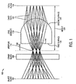
- FIG. 1 illustrates a layout of a single lens system 100 in accordance with one embodiment of the present invention.
- the single lens system 100 includes an object plane 104, a cover glass 108, an aperture 114, a singlet 118, and a focal plane 124.
- a height 128 is defined as the distance between the aperture 114 and the focal plane 124.
- An important aspect of the present invention is that the single lens system 100 has a small height so that the single lens system 100 can be incorporated into space-critical applications.
- Exemplary height values for the optics of the present invention include 6.2 mm and 4.4 mm.
- the height of the optics of the present invention is less than about 6mm.
- prior art systems have a typical height requirement for the optics that is about two times the height of the lens of the present invention.
- the lens 118 includes a first surface 134 for performing color correction functions and a second surface 138 for performing light ray bending functions.
- the first surface 134 has a mechanism for improving the diffraction efficiency of the lens.
- the diffraction efficiency improvement mechanism can be implemented with a portion 144 of the first surface 134 that reduces the incident angle of the light ray with respect to the first surface 134.
- the portion 144 preferably has a concave profile (e.g., a slightly concave profile).
- the first surface 134 is both diffractive and aspheric in nature
- the second surface 138 is primarily aspheric in nature.
- One aspect of the singlet design of the present invention is the telecentric nature of the singlet
- the design of the present invention positions the aperture with respect to the lens in such a way as to cause the chief rays 154 to be generally perpendicular to the focal plane 124.
- the distance 158 between the aperture 114 and the first surface 134 of the lens 118 is set to a predetermined distance in order to make the lens 118 generally telecentric in nature in order to reduce the amount of vignetting in the corners of the image.
- diffractive lens or optics are elements that use diffraction to control wave fronts of light.
- Diffractive optical elements may be made from glass or plastic and include a large number of fine grooves that are designed as described in greater detail hereinafter.
- the diffraction is employed in the image forming process.
- the diffractive lens of the present invention can be implemented by diffractive optics that include, but are not limited to, zone plates, holographic lenses, kinoform lenses, binary optics, or a combination thereof.
- the lens 118 of the present invention reduces vignetting or shadowing of the corners of the image.
- a telecentric system is a system in which the entrance pupil and/or exit pupil is located at infinity. It is noted that a telecentric system has better illumination than a non-telecentric system.
- the conic constant "k” is less than -1 for hyperbolas, -1 for parabolas, between -1 and 0 for ellipses, 0 for spheres, and greater than 1 for ellipsoids.
- a plane is a special case for a sphere with an infinite radius of curvature.
- the first surface 134 and the second surface 138 are rotationally symmetric polynomial aspheric surfaces.
- These aspheric surfaces can be designed using an even aspheric surface model that uses only the even powers of the radial coordinate to describe the aspheric nature of the surface. It is understood by those of ordinary skill in the art that aspheric surfaces can also be designed using an odd aspheric surface model that uses only the odd powers of the radial coordinate can also be used to describe the aspheric nature of the surface.
- the simplest optical surface for the lens is a spherical surface.
- the spherical surface alone is often insufficient or inadequate to correct all the aberration in order to obtain a good image.
- the aspheric constants are added one at a time to the basic spherical surface. Once added, the imaging quality of the resulting surface is examined. By iterating or repeating the steps of adding aspheric constants and examining the imaging quality of the resulting surface, the number and specific values of the aspheric constants are obtained.
- the first surface 134 and the second surface 138 are designed by using the above-noted expression.
- the diffractive nature of the first surface 134 can be achieved by using different diffractive groove depth values and diffractive groove width values.
- different diffractive groove depth values, different diffractive groove width values, and different combinations of these values are implemented in the design.
- the imaging quality of the resulting surface is examined. By iterating or repeating the steps of varying the groove depth values, diffractive groove width values, and the combinations thereof, and examining the imaging quality of the resulting surface, the final lens design is obtained.
- the lens of the present invention includes a diffractive surface that performs color correction.
- the present invention uses a first surface 134 with a portion 144 for focusing the different color light rays onto the same positions on the focal plane to increase the resolution of the lens.
- the lens 118 includes a first surface 134 for performing color correction functions and a second surface 138 for performing light ray bending functions.
- the first surface 134 has a portion 144 having a slightly concave profile for increasing the diffraction efficiency by reducing the incident angle of the light ray with respect to the surface.
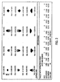
- FIG. 2 is a spot diagram of the singlet of FIG. 1.
- a spot diagram is analogous to a geometric point spread function (PSF). It is noted that diffraction effects are ignored
- PSD geometric point spread function
- the spot diagram illustrates the geometric image blur corresponding to a point object, such as a star.
- the spot diagram is utilized to examine or view the effects of aberrations.
- a spot diagram is constructed by starting with a single object point that emits a plurality of monochromatic rays (e.g., a cone of rays). These rays are aimed to uniformly fill the entrance pupil. These rays are then traced by employing trigonometry through the lens and onto the image surface. The aggregate of the points where the rays pierce the image surface is a spot diagram. In other words, when light rays are the trajectory of photons, and when a single monochromatic object point uniformly illuminates the entrance pupil, then a spot diagram is a map of the impact points of the photons on the image surface. It is noted that diffractions effects are not considered in a spot diagram.
- the object angle specifies the angle with respect to the optical axis at which light enters the first surface 134.
- the object angle is expressed in degrees.
- the IMA parameter specifies the distance in millimeters from the center of the focal plane to the location of the spot on the focal plane.
- This spot diagram illustrates twelve fields which are numbered from 1 to 12, that correspond to the sets of rays that are illustrated in FIG. 1 as groups of three generally parallel rays extending from the object plane 104 and passing the aperture 114. Each field has associated therewith a root mean square (RMS) radius (RMS RADIUS) and a geometric radius (GEO RADIUS) that are expressed in microns.
- RMS root mean square
- GEO RADIUS geometric radius
- the label OBJ refers to the object plane
- the label IMA refers to the imaging plane.
- the spot diagram illustrates that the lens 118 of FIG. 1 has excellent resolution across a wide field of view.
- the spot size is less than about 5 microns for a full field of view of about 110 degrees.
- the imaging spot radius across the imaging plane (IMA) are very uniform and at about five microns.
- prior art lens exhibit a similar spot size for a full field of view of only about 70 degrees.
- FIG. 3 illustrates a polychromatic diffraction modulation transfer function that is a measure of the resolution of the singlet of FIG. 1.
- the vertical axis represents the modulus of the optical transfer function (OTF), and the horizontal axis represents the spatial frequency in cycles per millimeter.
- FIG. 3 is a graph that illustrates the modulation transfer function of one embodiment of the lens. This graph indicates that the lens produces better than 15% of the modulation at 100 line-pair/mm across the sensor area.
- Resolution relates to the best feature that an optical system can resolve.
- the number of pixels in the imaging sensor typically defines the resolution of the system.
- the optical system e.g., lenses
- the lens of the present invention produces a spot size of less than or equal to the pixel dimensions. As illustrated in FIG. 2, the lens of the present invention can produce a spot size with dimensions of less than a five micron by five micron square area.
- FIG. 4 illustrates an exemplary digital image capture device 400 in which the singlet 410 of the present invention can be implemented.
- the digital image capture device 400 can be used to capture an object 420 (e.g., a tree) that is disposed at an object plane 424.
- the digital image capture device 400 includes an imaging sensor (e.g., a sensor integrated circuit) 430 that is disposed at the imaging plane 434.
- the digital image capture device 400 also includes imaging electronics 440 that is coupled to the imaging sensor 430 for performing image processing on the captured image.
- the lens 410 of the present invention can be implemented in the digital image capture device 400 as shown. It is noted that the height 460 is small (i.e., the distance between the aperture and the imaging plane is greatly reduced as compared to prior art optics that use two or more lenses).
- the optics of the present invention is especially suited for use in space-critical applications.
- These space critical applications can include electronic devices with small packaging requirements, such as cell phones and personal digital assistants (PDAs).
- PDAs personal digital assistants
- the single lens design (singlet) has a mechanism for reducing vignetting or shadowing of the corners of an image.
- the singlet of the present invention has a diffractive surface with high diffraction efficiency and provides a small spot size and excellent resolution over a large field of view.
- the lens of the present invention is a f2.8 wide field of view telecentric single lens design with a designed pixel (spot) size that is smaller than 5 microns across a 110 degree full diagonal field of view.
- the sensor is not subject to a color filter effect
- the front surface of the lens is designed so that a curvature primarily performs the ray bending while a diffractive surface performs the color correction to reduce and minimize the problem of stray light. It is noted that such a single lens design is well suited for digital imaging applications (e.g., CIF digital imaging application) and other applications with strict space requirements.
Landscapes
- Physics & Mathematics (AREA)
- General Physics & Mathematics (AREA)
- Optics & Photonics (AREA)
- Lenses (AREA)
Applications Claiming Priority (2)
| Application Number | Priority Date | Filing Date | Title |
|---|---|---|---|
| US10/087,278 US7102826B2 (en) | 2002-03-01 | 2002-03-01 | Telecentric singlet having a small height requirement |
| US87278 | 2002-03-01 |
Publications (3)
| Publication Number | Publication Date |
|---|---|
| EP1353207A2 EP1353207A2 (en) | 2003-10-15 |
| EP1353207A3 EP1353207A3 (en) | 2004-01-21 |
| EP1353207B1 true EP1353207B1 (en) | 2007-11-28 |
Family
ID=27803877
Family Applications (1)
| Application Number | Title | Priority Date | Filing Date |
|---|---|---|---|
| EP02023492A Expired - Lifetime EP1353207B1 (en) | 2002-03-01 | 2002-10-21 | Telecentric singlet having a small height requirement |
Country Status (4)
| Country | Link |
|---|---|
| US (1) | US7102826B2 (enExample) |
| EP (1) | EP1353207B1 (enExample) |
| JP (1) | JP2003262791A (enExample) |
| DE (1) | DE60223786T2 (enExample) |
Families Citing this family (5)
| Publication number | Priority date | Publication date | Assignee | Title |
|---|---|---|---|---|
| KR100859036B1 (ko) * | 2004-09-14 | 2008-09-17 | 씨디엠 옵틱스 인코퍼레이티드 | 촬상 시스템 및 관련 방법 |
| US20070258143A1 (en) * | 2006-05-08 | 2007-11-08 | Valdemar Portney | Aspheric multifocal diffractive ophthalmic lens |
| US20100002302A1 (en) * | 2008-07-01 | 2010-01-07 | Jacques Duparre | Method and apparatus for chief ray angle correction using a diffractive lens |
| JP6147405B1 (ja) * | 2016-11-04 | 2017-06-14 | エーエーシーアコースティックテクノロジーズ(シンセン)カンパニーリミテッドAAC Acoustic Technologies(Shenzhen)Co.,Ltd | 撮像レンズ |
| CN111175946B (zh) * | 2020-03-03 | 2021-10-15 | 莆田学院 | 一种高分辨率手机镜头光学系统 |
Family Cites Families (18)
| Publication number | Priority date | Publication date | Assignee | Title |
|---|---|---|---|---|
| JPS61189512A (ja) * | 1985-02-19 | 1986-08-23 | Canon Inc | 非球面単レンズ |
| JP3585297B2 (ja) * | 1995-09-12 | 2004-11-04 | オリンパス株式会社 | 対物レンズ |
| JP3833754B2 (ja) * | 1996-07-02 | 2006-10-18 | オリンパス株式会社 | 回折型光学素子を有する電子カメラ |
| JPH1090596A (ja) * | 1996-09-13 | 1998-04-10 | Matsushita Electric Ind Co Ltd | グレーティング素子付光学系およびこれを用いた撮像装置 |
| JPH10170820A (ja) * | 1996-12-13 | 1998-06-26 | Canon Inc | 回折光学素子を有した光学系 |
| JPH10282410A (ja) * | 1997-04-04 | 1998-10-23 | Hinode:Kk | Cctv用レンズ |
| TW582549U (en) * | 1997-09-24 | 2004-04-01 | Matsushita Electric Industrial Co Ltd | Calculating apparatus of diffraction efficiency of diffraction lens, lens with optical grating device and reading optical system |
| JPH11183794A (ja) * | 1997-12-19 | 1999-07-09 | Toshiba Corp | 光学レンズ |
| JP3686253B2 (ja) * | 1998-04-10 | 2005-08-24 | オリンパス株式会社 | 回折光学素子を用いたズームレンズ |
| JP2000249911A (ja) * | 1999-02-26 | 2000-09-14 | Enplas Corp | 撮像レンズ |
| JP2000266998A (ja) * | 1999-03-19 | 2000-09-29 | Olympus Optical Co Ltd | 撮像レンズ |
| US6507443B2 (en) * | 1999-12-02 | 2003-01-14 | Kabushiki Kaisha Toshiba | Lens, lens device, camera module and electrical equipment |
| JP2001296473A (ja) * | 2000-04-17 | 2001-10-26 | Milestone Kk | 撮影レンズ |
| JP2001350075A (ja) * | 2000-06-07 | 2001-12-21 | Enplas Corp | 撮像レンズ |
| JP2002055273A (ja) * | 2000-08-07 | 2002-02-20 | Enplas Corp | 撮像レンズ |
| KR100736628B1 (ko) * | 2001-05-11 | 2007-07-06 | 엘지.필립스 엘시디 주식회사 | 반사형 액정 표시 장치 |
| US6847498B2 (en) * | 2001-10-17 | 2005-01-25 | Inphase Technologies, Inc. | Holographic storage lenses |
| US6927922B2 (en) * | 2001-12-18 | 2005-08-09 | The University Of Rochester | Imaging using a multifocal aspheric lens to obtain extended depth of field |
-
2002
- 2002-03-01 US US10/087,278 patent/US7102826B2/en not_active Expired - Lifetime
- 2002-10-21 EP EP02023492A patent/EP1353207B1/en not_active Expired - Lifetime
- 2002-10-21 DE DE60223786T patent/DE60223786T2/de not_active Expired - Lifetime
-
2003
- 2003-02-26 JP JP2003049158A patent/JP2003262791A/ja active Pending
Also Published As
| Publication number | Publication date |
|---|---|
| US20030165023A1 (en) | 2003-09-04 |
| EP1353207A3 (en) | 2004-01-21 |
| US7102826B2 (en) | 2006-09-05 |
| DE60223786T2 (de) | 2008-10-23 |
| DE60223786D1 (de) | 2008-01-10 |
| JP2003262791A (ja) | 2003-09-19 |
| EP1353207A2 (en) | 2003-10-15 |
Similar Documents
| Publication | Publication Date | Title |
|---|---|---|
| US12429671B2 (en) | Optical imaging system | |
| US12481128B2 (en) | Optical imaging system, image capturing unit and electronic device | |
| TWI601994B (zh) | 取像用光學鏡頭組、取像裝置及電子裝置 | |
| US12596239B2 (en) | Electronic device | |
| CN209570744U (zh) | 光学成像系统和多构件光学成像系统 | |
| TWI595261B (zh) | 攝像用光學鏡頭組、取像裝置及電子裝置 | |
| US10514523B2 (en) | Optical image capturing system and electronic device | |
| US12111446B2 (en) | Optical imaging system comprising four lenses of - -+-, +-+-, +++- or -++- refractive powers, image capturing unit and electronic device | |
| US11391919B2 (en) | Imaging lens assembly, image capturing unit and electronic device | |
| US20150085382A1 (en) | Wide-angle photographic lens system enabling correction of distortion | |
| CN109239891A (zh) | 光学成像透镜组 | |
| CN110426829A (zh) | 摄像用光学镜头组、取像装置及电子装置 | |
| CN108152936A (zh) | 镜头和成像装置 | |
| KR20170001640U (ko) | 근적외선 이미징 렌즈 | |
| EP2212732A1 (en) | Customized depth of field optical system and compact fast lens architecture | |
| CN112578532A (zh) | 光学镜头、摄像头模组和终端 | |
| EP1353207B1 (en) | Telecentric singlet having a small height requirement | |
| US10948690B2 (en) | Photographing optical lens assembly, image capturing unit and electronic device | |
| CN116430543B (zh) | 成像透镜组及摄像模块 | |
| KR101872857B1 (ko) | 초소형 광각 촬상 렌즈 시스템 | |
| CN112034593B (zh) | 光学成像系统、取像模组及电子装置 | |
| KR20190088716A (ko) | 광각 촬상 광학계 | |
| CN219978613U (zh) | 光学系统、摄像模组和电子设备 | |
| CN116819732B (zh) | 光学系统、摄像模组和电子设备 | |
| US8422147B2 (en) | Image pickup lens and image pickup module |
Legal Events
| Date | Code | Title | Description |
|---|---|---|---|
| PUAI | Public reference made under article 153(3) epc to a published international application that has entered the european phase |
Free format text: ORIGINAL CODE: 0009012 |
|
| AK | Designated contracting states |
Kind code of ref document: A2 Designated state(s): AT BE BG CH CY CZ DE DK EE ES FI FR GB GR IE IT LI LU MC NL PT SE SK TR |
|
| AX | Request for extension of the european patent |
Extension state: AL LT LV MK RO SI |
|
| PUAL | Search report despatched |
Free format text: ORIGINAL CODE: 0009013 |
|
| AK | Designated contracting states |
Kind code of ref document: A3 Designated state(s): AT BE BG CH CY CZ DE DK EE ES FI FR GB GR IE IT LI LU MC NL PT SE SK TR |
|
| AX | Request for extension of the european patent |
Extension state: AL LT LV MK RO SI |
|
| RIC1 | Information provided on ipc code assigned before grant |
Ipc: 7G 02B 13/22 A Ipc: 7G 02B 13/18 B Ipc: 7G 02B 5/18 B Ipc: 7G 02B 13/00 B |
|
| 17P | Request for examination filed |
Effective date: 20040507 |
|
| AKX | Designation fees paid |
Designated state(s): DE FR GB |
|
| 17Q | First examination report despatched |
Effective date: 20040916 |
|
| RAP1 | Party data changed (applicant data changed or rights of an application transferred) |
Owner name: AGILENT TECHNOLOGIES, INC. |
|
| GRAP | Despatch of communication of intention to grant a patent |
Free format text: ORIGINAL CODE: EPIDOSNIGR1 |
|
| GRAS | Grant fee paid |
Free format text: ORIGINAL CODE: EPIDOSNIGR3 |
|
| GRAA | (expected) grant |
Free format text: ORIGINAL CODE: 0009210 |
|
| AK | Designated contracting states |
Kind code of ref document: B1 Designated state(s): DE FR GB |
|
| REF | Corresponds to: |
Ref document number: 60223786 Country of ref document: DE Date of ref document: 20080110 Kind code of ref document: P |
|
| ET | Fr: translation filed | ||
| REG | Reference to a national code |
Ref country code: GB Ref legal event code: 732E |
|
| PLBE | No opposition filed within time limit |
Free format text: ORIGINAL CODE: 0009261 |
|
| STAA | Information on the status of an ep patent application or granted ep patent |
Free format text: STATUS: NO OPPOSITION FILED WITHIN TIME LIMIT |
|
| 26N | No opposition filed |
Effective date: 20080829 |
|
| REG | Reference to a national code |
Ref country code: FR Ref legal event code: TP |
|
| REG | Reference to a national code |
Ref country code: FR Ref legal event code: RM |
|
| REG | Reference to a national code |
Ref country code: GB Ref legal event code: 732E Free format text: REGISTERED BETWEEN 20101007 AND 20101013 |
|
| PGFP | Annual fee paid to national office [announced via postgrant information from national office to epo] |
Ref country code: FR Payment date: 20111103 Year of fee payment: 10 |
|
| REG | Reference to a national code |
Ref country code: FR Ref legal event code: ST Effective date: 20130628 |
|
| PG25 | Lapsed in a contracting state [announced via postgrant information from national office to epo] |
Ref country code: FR Free format text: LAPSE BECAUSE OF NON-PAYMENT OF DUE FEES Effective date: 20121031 |
|
| PGFP | Annual fee paid to national office [announced via postgrant information from national office to epo] |
Ref country code: GB Payment date: 20180925 Year of fee payment: 17 |
|
| GBPC | Gb: european patent ceased through non-payment of renewal fee |
Effective date: 20191021 |
|
| PG25 | Lapsed in a contracting state [announced via postgrant information from national office to epo] |
Ref country code: GB Free format text: LAPSE BECAUSE OF NON-PAYMENT OF DUE FEES Effective date: 20191021 |
|
| PGFP | Annual fee paid to national office [announced via postgrant information from national office to epo] |
Ref country code: DE Payment date: 20210921 Year of fee payment: 20 |
|
| REG | Reference to a national code |
Ref country code: DE Ref legal event code: R071 Ref document number: 60223786 Country of ref document: DE |