EP1353047B1 - Vorrichtung zur Behandlung von Abgas - Google Patents
Vorrichtung zur Behandlung von Abgas Download PDFInfo
- Publication number
- EP1353047B1 EP1353047B1 EP20030252272 EP03252272A EP1353047B1 EP 1353047 B1 EP1353047 B1 EP 1353047B1 EP 20030252272 EP20030252272 EP 20030252272 EP 03252272 A EP03252272 A EP 03252272A EP 1353047 B1 EP1353047 B1 EP 1353047B1
- Authority
- EP
- European Patent Office
- Prior art keywords
- canister
- retainer
- tubular
- compartment
- treatment
- Prior art date
- Legal status (The legal status is an assumption and is not a legal conclusion. Google has not performed a legal analysis and makes no representation as to the accuracy of the status listed.)
- Expired - Lifetime
Links
Images

Classifications
-
- F—MECHANICAL ENGINEERING; LIGHTING; HEATING; WEAPONS; BLASTING
- F01—MACHINES OR ENGINES IN GENERAL; ENGINE PLANTS IN GENERAL; STEAM ENGINES
- F01N—GAS-FLOW SILENCERS OR EXHAUST APPARATUS FOR MACHINES OR ENGINES IN GENERAL; GAS-FLOW SILENCERS OR EXHAUST APPARATUS FOR INTERNAL COMBUSTION ENGINES
- F01N13/00—Exhaust or silencing apparatus characterised by constructional features ; Exhaust or silencing apparatus, or parts thereof, having pertinent characteristics not provided for in, or of interest apart from, groups F01N1/00 - F01N5/00, F01N9/00, F01N11/00
- F01N13/18—Construction facilitating manufacture, assembly, or disassembly
- F01N13/1838—Construction facilitating manufacture, assembly, or disassembly characterised by the type of connection between parts of exhaust or silencing apparatus, e.g. between housing and tubes, between tubes and baffles
-
- F—MECHANICAL ENGINEERING; LIGHTING; HEATING; WEAPONS; BLASTING
- F01—MACHINES OR ENGINES IN GENERAL; ENGINE PLANTS IN GENERAL; STEAM ENGINES
- F01N—GAS-FLOW SILENCERS OR EXHAUST APPARATUS FOR MACHINES OR ENGINES IN GENERAL; GAS-FLOW SILENCERS OR EXHAUST APPARATUS FOR INTERNAL COMBUSTION ENGINES
- F01N13/00—Exhaust or silencing apparatus characterised by constructional features ; Exhaust or silencing apparatus, or parts thereof, having pertinent characteristics not provided for in, or of interest apart from, groups F01N1/00 - F01N5/00, F01N9/00, F01N11/00
- F01N13/009—Exhaust or silencing apparatus characterised by constructional features ; Exhaust or silencing apparatus, or parts thereof, having pertinent characteristics not provided for in, or of interest apart from, groups F01N1/00 - F01N5/00, F01N9/00, F01N11/00 having two or more separate purifying devices arranged in series
- F01N13/0097—Exhaust or silencing apparatus characterised by constructional features ; Exhaust or silencing apparatus, or parts thereof, having pertinent characteristics not provided for in, or of interest apart from, groups F01N1/00 - F01N5/00, F01N9/00, F01N11/00 having two or more separate purifying devices arranged in series the purifying devices are arranged in a single housing
-
- F—MECHANICAL ENGINEERING; LIGHTING; HEATING; WEAPONS; BLASTING
- F01—MACHINES OR ENGINES IN GENERAL; ENGINE PLANTS IN GENERAL; STEAM ENGINES
- F01N—GAS-FLOW SILENCERS OR EXHAUST APPARATUS FOR MACHINES OR ENGINES IN GENERAL; GAS-FLOW SILENCERS OR EXHAUST APPARATUS FOR INTERNAL COMBUSTION ENGINES
- F01N13/00—Exhaust or silencing apparatus characterised by constructional features ; Exhaust or silencing apparatus, or parts thereof, having pertinent characteristics not provided for in, or of interest apart from, groups F01N1/00 - F01N5/00, F01N9/00, F01N11/00
- F01N13/18—Construction facilitating manufacture, assembly, or disassembly
- F01N13/1888—Construction facilitating manufacture, assembly, or disassembly the housing of the assembly consisting of two or more parts, e.g. two half-shells
- F01N13/1894—Construction facilitating manufacture, assembly, or disassembly the housing of the assembly consisting of two or more parts, e.g. two half-shells the parts being assembled in longitudinal direction
-
- F—MECHANICAL ENGINEERING; LIGHTING; HEATING; WEAPONS; BLASTING
- F01—MACHINES OR ENGINES IN GENERAL; ENGINE PLANTS IN GENERAL; STEAM ENGINES
- F01N—GAS-FLOW SILENCERS OR EXHAUST APPARATUS FOR MACHINES OR ENGINES IN GENERAL; GAS-FLOW SILENCERS OR EXHAUST APPARATUS FOR INTERNAL COMBUSTION ENGINES
- F01N3/00—Exhaust or silencing apparatus having means for purifying, rendering innocuous, or otherwise treating exhaust
- F01N3/02—Exhaust or silencing apparatus having means for purifying, rendering innocuous, or otherwise treating exhaust for cooling, or for removing solid constituents of, exhaust
- F01N3/021—Exhaust or silencing apparatus having means for purifying, rendering innocuous, or otherwise treating exhaust for cooling, or for removing solid constituents of, exhaust by means of filters
- F01N3/0211—Arrangements for mounting filtering elements in housing, e.g. with means for compensating thermal expansion or vibration
-
- F—MECHANICAL ENGINEERING; LIGHTING; HEATING; WEAPONS; BLASTING
- F01—MACHINES OR ENGINES IN GENERAL; ENGINE PLANTS IN GENERAL; STEAM ENGINES
- F01N—GAS-FLOW SILENCERS OR EXHAUST APPARATUS FOR MACHINES OR ENGINES IN GENERAL; GAS-FLOW SILENCERS OR EXHAUST APPARATUS FOR INTERNAL COMBUSTION ENGINES
- F01N3/00—Exhaust or silencing apparatus having means for purifying, rendering innocuous, or otherwise treating exhaust
- F01N3/02—Exhaust or silencing apparatus having means for purifying, rendering innocuous, or otherwise treating exhaust for cooling, or for removing solid constituents of, exhaust
- F01N3/021—Exhaust or silencing apparatus having means for purifying, rendering innocuous, or otherwise treating exhaust for cooling, or for removing solid constituents of, exhaust by means of filters
- F01N3/033—Exhaust or silencing apparatus having means for purifying, rendering innocuous, or otherwise treating exhaust for cooling, or for removing solid constituents of, exhaust by means of filters in combination with other devices
- F01N3/0335—Exhaust or silencing apparatus having means for purifying, rendering innocuous, or otherwise treating exhaust for cooling, or for removing solid constituents of, exhaust by means of filters in combination with other devices with exhaust silencers in a single housing
-
- F—MECHANICAL ENGINEERING; LIGHTING; HEATING; WEAPONS; BLASTING
- F01—MACHINES OR ENGINES IN GENERAL; ENGINE PLANTS IN GENERAL; STEAM ENGINES
- F01N—GAS-FLOW SILENCERS OR EXHAUST APPARATUS FOR MACHINES OR ENGINES IN GENERAL; GAS-FLOW SILENCERS OR EXHAUST APPARATUS FOR INTERNAL COMBUSTION ENGINES
- F01N3/00—Exhaust or silencing apparatus having means for purifying, rendering innocuous, or otherwise treating exhaust
- F01N3/02—Exhaust or silencing apparatus having means for purifying, rendering innocuous, or otherwise treating exhaust for cooling, or for removing solid constituents of, exhaust
- F01N3/021—Exhaust or silencing apparatus having means for purifying, rendering innocuous, or otherwise treating exhaust for cooling, or for removing solid constituents of, exhaust by means of filters
- F01N3/033—Exhaust or silencing apparatus having means for purifying, rendering innocuous, or otherwise treating exhaust for cooling, or for removing solid constituents of, exhaust by means of filters in combination with other devices
- F01N3/035—Exhaust or silencing apparatus having means for purifying, rendering innocuous, or otherwise treating exhaust for cooling, or for removing solid constituents of, exhaust by means of filters in combination with other devices with catalytic reactors, e.g. catalysed diesel particulate filters
-
- F—MECHANICAL ENGINEERING; LIGHTING; HEATING; WEAPONS; BLASTING
- F01—MACHINES OR ENGINES IN GENERAL; ENGINE PLANTS IN GENERAL; STEAM ENGINES
- F01N—GAS-FLOW SILENCERS OR EXHAUST APPARATUS FOR MACHINES OR ENGINES IN GENERAL; GAS-FLOW SILENCERS OR EXHAUST APPARATUS FOR INTERNAL COMBUSTION ENGINES
- F01N3/00—Exhaust or silencing apparatus having means for purifying, rendering innocuous, or otherwise treating exhaust
- F01N3/08—Exhaust or silencing apparatus having means for purifying, rendering innocuous, or otherwise treating exhaust for rendering innocuous
- F01N3/10—Exhaust or silencing apparatus having means for purifying, rendering innocuous, or otherwise treating exhaust for rendering innocuous by thermal or catalytic conversion of noxious components of exhaust
- F01N3/24—Exhaust or silencing apparatus having means for purifying, rendering innocuous, or otherwise treating exhaust for rendering innocuous by thermal or catalytic conversion of noxious components of exhaust characterised by constructional aspects of converting apparatus
- F01N3/28—Construction of catalytic reactors
- F01N3/2839—Arrangements for mounting catalyst support in housing, e.g. with means for compensating thermal expansion or vibration
- F01N3/2853—Arrangements for mounting catalyst support in housing, e.g. with means for compensating thermal expansion or vibration using mats or gaskets between catalyst body and housing
-
- F—MECHANICAL ENGINEERING; LIGHTING; HEATING; WEAPONS; BLASTING
- F01—MACHINES OR ENGINES IN GENERAL; ENGINE PLANTS IN GENERAL; STEAM ENGINES
- F01N—GAS-FLOW SILENCERS OR EXHAUST APPARATUS FOR MACHINES OR ENGINES IN GENERAL; GAS-FLOW SILENCERS OR EXHAUST APPARATUS FOR INTERNAL COMBUSTION ENGINES
- F01N3/00—Exhaust or silencing apparatus having means for purifying, rendering innocuous, or otherwise treating exhaust
- F01N3/08—Exhaust or silencing apparatus having means for purifying, rendering innocuous, or otherwise treating exhaust for rendering innocuous
- F01N3/10—Exhaust or silencing apparatus having means for purifying, rendering innocuous, or otherwise treating exhaust for rendering innocuous by thermal or catalytic conversion of noxious components of exhaust
- F01N3/24—Exhaust or silencing apparatus having means for purifying, rendering innocuous, or otherwise treating exhaust for rendering innocuous by thermal or catalytic conversion of noxious components of exhaust characterised by constructional aspects of converting apparatus
- F01N3/28—Construction of catalytic reactors
- F01N3/2882—Catalytic reactors combined or associated with other devices, e.g. exhaust silencers or other exhaust purification devices
- F01N3/2885—Catalytic reactors combined or associated with other devices, e.g. exhaust silencers or other exhaust purification devices with exhaust silencers in a single housing
-
- F—MECHANICAL ENGINEERING; LIGHTING; HEATING; WEAPONS; BLASTING
- F01—MACHINES OR ENGINES IN GENERAL; ENGINE PLANTS IN GENERAL; STEAM ENGINES
- F01N—GAS-FLOW SILENCERS OR EXHAUST APPARATUS FOR MACHINES OR ENGINES IN GENERAL; GAS-FLOW SILENCERS OR EXHAUST APPARATUS FOR INTERNAL COMBUSTION ENGINES
- F01N2230/00—Combination of silencers and other devices
- F01N2230/02—Exhaust filters
-
- F—MECHANICAL ENGINEERING; LIGHTING; HEATING; WEAPONS; BLASTING
- F01—MACHINES OR ENGINES IN GENERAL; ENGINE PLANTS IN GENERAL; STEAM ENGINES
- F01N—GAS-FLOW SILENCERS OR EXHAUST APPARATUS FOR MACHINES OR ENGINES IN GENERAL; GAS-FLOW SILENCERS OR EXHAUST APPARATUS FOR INTERNAL COMBUSTION ENGINES
- F01N2230/00—Combination of silencers and other devices
- F01N2230/04—Catalytic converters
-
- F—MECHANICAL ENGINEERING; LIGHTING; HEATING; WEAPONS; BLASTING
- F01—MACHINES OR ENGINES IN GENERAL; ENGINE PLANTS IN GENERAL; STEAM ENGINES
- F01N—GAS-FLOW SILENCERS OR EXHAUST APPARATUS FOR MACHINES OR ENGINES IN GENERAL; GAS-FLOW SILENCERS OR EXHAUST APPARATUS FOR INTERNAL COMBUSTION ENGINES
- F01N2240/00—Combination or association of two or more different exhaust treating devices, or of at least one such device with an auxiliary device, not covered by indexing codes F01N2230/00 or F01N2250/00, one of the devices being
- F01N2240/20—Combination or association of two or more different exhaust treating devices, or of at least one such device with an auxiliary device, not covered by indexing codes F01N2230/00 or F01N2250/00, one of the devices being a flow director or deflector
-
- F—MECHANICAL ENGINEERING; LIGHTING; HEATING; WEAPONS; BLASTING
- F01—MACHINES OR ENGINES IN GENERAL; ENGINE PLANTS IN GENERAL; STEAM ENGINES
- F01N—GAS-FLOW SILENCERS OR EXHAUST APPARATUS FOR MACHINES OR ENGINES IN GENERAL; GAS-FLOW SILENCERS OR EXHAUST APPARATUS FOR INTERNAL COMBUSTION ENGINES
- F01N2250/00—Combinations of different methods of purification
- F01N2250/02—Combinations of different methods of purification filtering and catalytic conversion
-
- F—MECHANICAL ENGINEERING; LIGHTING; HEATING; WEAPONS; BLASTING
- F01—MACHINES OR ENGINES IN GENERAL; ENGINE PLANTS IN GENERAL; STEAM ENGINES
- F01N—GAS-FLOW SILENCERS OR EXHAUST APPARATUS FOR MACHINES OR ENGINES IN GENERAL; GAS-FLOW SILENCERS OR EXHAUST APPARATUS FOR INTERNAL COMBUSTION ENGINES
- F01N2330/00—Structure of catalyst support or particle filter
- F01N2330/06—Ceramic, e.g. monoliths
-
- F—MECHANICAL ENGINEERING; LIGHTING; HEATING; WEAPONS; BLASTING
- F01—MACHINES OR ENGINES IN GENERAL; ENGINE PLANTS IN GENERAL; STEAM ENGINES
- F01N—GAS-FLOW SILENCERS OR EXHAUST APPARATUS FOR MACHINES OR ENGINES IN GENERAL; GAS-FLOW SILENCERS OR EXHAUST APPARATUS FOR INTERNAL COMBUSTION ENGINES
- F01N2450/00—Methods or apparatus for fitting, inserting or repairing different elements
- F01N2450/30—Removable or rechangeable blocks or cartridges, e.g. for filters
-
- F—MECHANICAL ENGINEERING; LIGHTING; HEATING; WEAPONS; BLASTING
- F01—MACHINES OR ENGINES IN GENERAL; ENGINE PLANTS IN GENERAL; STEAM ENGINES
- F01N—GAS-FLOW SILENCERS OR EXHAUST APPARATUS FOR MACHINES OR ENGINES IN GENERAL; GAS-FLOW SILENCERS OR EXHAUST APPARATUS FOR INTERNAL COMBUSTION ENGINES
- F01N2470/00—Structure or shape of gas passages, pipes or tubes
- F01N2470/18—Structure or shape of gas passages, pipes or tubes the axis of inlet or outlet tubes being other than the longitudinal axis of apparatus
-
- F—MECHANICAL ENGINEERING; LIGHTING; HEATING; WEAPONS; BLASTING
- F01—MACHINES OR ENGINES IN GENERAL; ENGINE PLANTS IN GENERAL; STEAM ENGINES
- F01N—GAS-FLOW SILENCERS OR EXHAUST APPARATUS FOR MACHINES OR ENGINES IN GENERAL; GAS-FLOW SILENCERS OR EXHAUST APPARATUS FOR INTERNAL COMBUSTION ENGINES
- F01N2470/00—Structure or shape of gas passages, pipes or tubes
- F01N2470/22—Inlet and outlet tubes being positioned on the same side of the apparatus
-
- F—MECHANICAL ENGINEERING; LIGHTING; HEATING; WEAPONS; BLASTING
- F01—MACHINES OR ENGINES IN GENERAL; ENGINE PLANTS IN GENERAL; STEAM ENGINES
- F01N—GAS-FLOW SILENCERS OR EXHAUST APPARATUS FOR MACHINES OR ENGINES IN GENERAL; GAS-FLOW SILENCERS OR EXHAUST APPARATUS FOR INTERNAL COMBUSTION ENGINES
- F01N2530/00—Selection of materials for tubes, chambers or housings
- F01N2530/02—Corrosion resistive metals
- F01N2530/04—Steel alloys, e.g. stainless steel
Definitions
- the present invention relates to gas treatment apparatus for treating an exhaust gas stream from an internal combustion engine, particularly gas treatment apparatus for an internal combustion engine in a motor vehicle.
- Internal combustion engines particularly diesel engines produce an exhaust gas stream that contains a number of noxious gases, unburned hydrocarbons and particulates. It is desirable to treat the exhaust gas stream to render it less obnoxious.
- a silencer assembly that contains one or more treatment compartments containing a treatment element, such as a catalytic converter or a filter to remove particulates.
- the treatment compartments within a silencer assembly are typically tubular and are a close fit with the treatment element that it contains.
- a treatment element is usually axially secured in a treatment compartment such that the treatment element cannot move during use.
- the silencer assembly may also serve to attenuate the noise emitted by the engine.
- a treatment element typically comprises a cylindrical body member surrounded by a shock absorbing sleeve within a metal tubular case, usually stainless steel.
- the body member and sleeve are secured within the tubular case by internally directed ribs or flanges and gaskets at both ends of the body member.
- a gas stream is treated by being passed through the body member of a treatment element.
- the body member may comprise a catalyst carried on a ceramic support, or it may comprise a ceramic filter which traps the particulates in the gas stream, or it may comprise any other type of gas treatment member.
- a flanged part to the outside of the tubular case as shown in Figures 1 and 2.
- a flanged part is welded to the tubular case of a treatment element and the flange is secured to a corresponding flange on the chamber by a V-clamp.
- a second flanged part is also welded to the tubular case to ensure the symmetry of the treatment element for refitting in the reverse orientation.
- the flanged part increases the complexity of manufacture of the treatment element and increases the possibility of heat damage to the body member.
- an apparatus for treating an exhaust gas stream from an internal combustion engine comprising a tubular compartment containing a treatment member through which a gas stream to be treated is to flow, the tubular compartment being substantially surrounded by an annular compartment through which gas may flow, the tubular compartment comprising a tubular canister and a retainer, the tubular canister including stopping means, the retainer being releasably attached to the canister by axial clamping means and the treatment member being secured within the tubular compartment by contact of a first end of the treatment member with the stopping means and contact of a second end of the treatment member with the retainer.
- the invention also provides apparatus for housing a treatment member for treating a gas stream from an internal combustion engine, said apparatus comprising a tubular compartment for containing the treatment member through which a gas stream to be treated is to flow, the tubular compartment being substantially surrounded by an annular compartment through which gas may flow, the tubular compartment comprising a tubular canister and a tubular retainer, the tubular canister including stopping means and a substantially radially outwardly protruding flange, the tubular retainer including a substantially radially outwardly protruding flange and a substantially radially inwardly protruding flange, the tubular retainer being releasably attachable to the canister by axial clamping means acting on the substantially radially outwardly protruding flanges such that, in use, a treatment member may be secured within the compartment by contact of the treatment member with the stopping means and the substantially radially inwardly protruding flange.
- the treatment member may be a single treatment element, or may be a combination of two or more treatment elements or a combination of one or more treatment elements and other elements such as a flame trap, inlet or outlet module or noise attenuation module. Preferably the elements are combined in series. For convenience, the present invention will be described hereafter with reference to an embodiment in which the treatment member is a single treatment element.
- a gas treatment apparatus is therefore provided that may be used in several different designs and/or for different duties by including different retainers for the same canister.
- the tubular canister can have any cross-section, but it is preferably substantially circular or substantially elliptical, as these shapes can be manufactured using rolling techniques.
- Axial clamping means secure the retainer to the canister by applying an axial force across the joint between the canister and the retainer.
- the use of an axial clamping means such as an adjustable axial strap, V-clamp, a plurality of clamps or clips or other means may allow an axial force to be applied to the treatment element towards the stopping means, thereby securing the treatment element within the compartment.
- the axial clamping means may be attached to either the compartment or to the retainer, but is preferably separate.
- the canister and retainer may comprise one or more substantially radially outwardly projecting flanges, but preferably each comprise a circumferential flange around their periphery upon which the axial clamping means may act to attach the canister and retainer together.
- the attachment is preferably by clamping the outwardly projecting flanges together using a V-clamp.
- the joint may further comprise a gasket or other seal that may prevent gas flow through the joint, or between the canister and treatment element.
- a V-clamp is typically formed from a strap with a V-shaped cross section that is formed into a hoop such that the opening of the 'V' is directed substantially radially inwards.
- the ends of the length of material are secured together by an adjustable fastening such that the length of the perimeter of the hoop can be altered by adjusting the fastening.
- a V-clamp may be used to secure tubular parts together if each part has a radially outwardly projecting flange. The two parts are brought together such that the flanges are adjacent one another and the V-clamp is then arranged such that the flanges are within the opening of the 'V' shape. The perimeter of the strap is then shortened so that the flanges are forced together axially as the flanges enter the 'V' and the parts are secured together. It should be understood that the invention is not limited to this construction of V-clamp.
- the stopping means prevent the treatment element from moving further into the canister.
- the stopping means may be a substantially radially inwardly directed shoulder or flange that makes contact with an end of the treatment element and prevents axial movement into the canister. It should be understood that other stopping means could also be used, for instance an additional retainer.
- the retainer comprises a tubular portion with substantially the same cross section as the tubular canister.
- the retainer can therefore be attached to the canister and still make contact with an end of the treatment element if the element is longer than the canister.
- This allows different lengths of treatment elements to be accommodated within a canister by changing the retainer.
- the cross section of the retainer is slightly smaller than the cross section of the canister, it may be possible for the retainer to slide into the canister and retain a treatment element that is shorter than the canister.
- the retainer may also include an inlet or outlet pipe and serve as the inlet or outlet to the compartment through which gas enters or leaves the compartment.
- the retainer and stopping means preferably make contact with the ends of the treatment element at or adjacent the periphery of the treatment element so that the gas flow through the treatment element is not substantially hindered.
- the currently preferred retainer comprises a tubular portion, with a substantially radially outwardly projecting circumferential flange at or adjacent one end of the tubular portion and a substantially radially inwardly directed circumferential flange at the opposing end of the tubular portion.
- the tubular portion preferably has a cross section that is substantially identical with the cross section of the canister.
- the canister is preferably shorter than the treatment element to be located within it such that the element protrudes from the canister when it is located against the stopping means as this allows for easier extraction of the filter element.
- the treatment element is less than about 50% longer than the canister and preferably less than about 25%.
- the canister and retainer can be fabricated from any suitable material, it is preferred that they are fabricated from stainless steel, as it is highly corrosion resistant.
- a method for securing a treatment within the compartment is for the treatment element to be inserted into the tubular canister until it reaches the stopping means, an end of the treatment element remaining protruding from the canister.
- the retainer is then fitted over the protruding end of the treatment element such that the inwardly protruding flange of the retainer is in contact with the end of the treatment element.
- the outwardly protruding circumferential flange of the retainer is then adjacent to the corresponding outwardly protruding circumferential flange of the tubular canister and a V-clamp is then used to secure the retainer to the canister and hence secure the treatment element within the compartment.
- This invention is of particular use because the compartment forms a central compartment and has an annular compartment that substantially surrounds it.
- the invention is of particular use because of the increased difficulty in obtaining access to the treatment element within the central compartment.
- a gas treatment apparatus it is common practice to have a removable endcap which allows access to an end of the central compartment. It is desirable that the axial clamping means is easily accessible once the endcap has been removed. It is therefore preferred that the retainer is located at the end of the canister closest to the removable endcap.
- Such an embodiment according to the present invention also provides the advantage over known embodiments that the canister can be permanently supported at both ends, thereby supporting the treatment element.
- the canister can be permanently supported at both ends, thereby supporting the treatment element.
- Such a support requires careful manufacture and fitting to ensure that it supports the treatment element when the removable endcap is fitted.
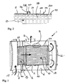
- Figure 1 shows a known gas treatment apparatus 1 having a central tubular compartment 2 and an annular compartment 4 substantially surrounding the central compartment 2.
- a gas stream enters the apparatus 1 through an inlet 6 and passes into a catalytic treatment element 8 in the central compartment 2.
- the gas stream then passes into a filter element 10.
- the direction of the gas flow is then reversed by a contact with an endwall 12 and the gas flows through the annular compartment 4 to an outlet 14.
- the direction of gas flow is indicated by arrows 15.
- the catalytic treatment element 8 is for catalytic oxidation of at least some of the chemicals in the gas stream and is a Platinum based catalyst on a ceramic frit support.
- the filter 10 is a ceramic wall flow filter for removing particulates from the gas stream.
- Each treatment element 8,10 comprises a respective body member 16,18 surrounded by a shock absorbing sleeve 20 within a tubular case 22.
- the catalytic treatment element 8 is permanently secured within the central compartment 2, but the filter element 10 is releasably attached to the central compartment 2 by a V-clamp 24.
- the nature of the attachment is best shown in Figure 2.
- the outside of the tubular case 22 surrounding the filter element 10 has two circumferential flanged parts 26,28 welded it.
- the flanged parts 26,28 include substantially radially outwardly protruding flanges 30,32.
- the central compartment 2 includes a substantially radially outwardly directed circumferential flange 34. When the filter element 10 is fully inserted into the central compartment 2 in a first orientation, the flange 34 on the central compartment 2 is adjacent a flange 30 of the flanged part 26.
- the V-clamp 24 can be used to secure the flanges 34,30 together to hold the treatment element 10 in the central compartment in a first orientation.
- the flange 34 on the central compartment 2 is adjacent a flange 32 of the flanged part 28.
- the V-clamp 24 can then be used to secure the flanges 34,30 together to hold the treatment element 10 in the central compartment in a second orientation.
- FIG 3 shows a gas treatment apparatus 101 according to the present invention. Features that have the same function as described for the embodiment 1 of Figure 1 will be referenced by the same numerals.
- the compartment 102 comprises a tubular canister 42 and a retainer 36.
- the retainer comprises a tubular portion 44 with a substantially radially outwardly projecting circumferential flange 40 at one end and a substantially inwardly projecting flange 38.
- the canister includes a substantially radially outwardly projecting circumferential flange 34.
- the treatment member in this case a treatment element 110, is located within the canister 42 and rests against stopping means 46, in this case an inwardly directed shoulder. An end of the treatment element 110 protrudes from the canister 42.
- the retainer is fitted over the protruding end until the radially inwardly protruding circumferential flange 38 makes contact with the end of the treatment element 110.
- the radially outwardly projecting flanges 34,40 are adjacent one another and a V-clamp 24 acts on the flanges 34,40 to axially clamp the retainer 36 to the canister 42.
- the axial clamping by the V-clamp applies a force on the treatment element 110 towards the stopping means 46 to secure the treatment element within the compartment 2.
- the filter element 110 is of standard construction and does not have any additional parts attached to the outside. Although the treatment member is shown as a single treatment element 110 for simplicity, it should be understood that the treatment member could also include a flame trap, noise attenuation module or other element.
- Figure 4 shows a close up of the attachment between the retainer 36 and the canister 42. This figure shows the position of two different retainers 36,36'.
- the retainer 36 is longer than the retainer 36' and can therefore be used to secure longer filter elements 110 within the compartment 102.
- the retainer 36 is of simple construction and can be easily fabricated. If the endcap 12 is removed from the apparatus 101 it allows access to remove the V-clamp 24 and retainer 36 and hence allows the removal of the treatment element 110 from the compartment 102. The treatment element 110 can then be serviced and replaced, or substituted for a different treatment element of substantially the same diameter which need not have been specially adapted for use in the compartment 102.
Landscapes
- Engineering & Computer Science (AREA)
- Chemical & Material Sciences (AREA)
- Combustion & Propulsion (AREA)
- Mechanical Engineering (AREA)
- General Engineering & Computer Science (AREA)
- Chemical Kinetics & Catalysis (AREA)
- Health & Medical Sciences (AREA)
- Toxicology (AREA)
- Exhaust Gas After Treatment (AREA)
- Processes For Solid Components From Exhaust (AREA)
Claims (10)
- Vorrichtung (101) zur Behandlung eines Abgasstroms von einem Verbrennungsmotor, wobei die Vorrichtung (101) eine röhrenförmige Kammer (102) umfasst, die ein Behandlungsglied (110) enthält, durch das ein zu behandelnder Gasstrom strömen soll, wobei die röhrenförmige Kammer (102) von einer ringförmigen Kammer (4), durch die Gas strömen kann, im Wesentlichen umgeben wird, dadurch gekennzeichnet, dass die röhrenförmige Kammer (102) einen röhrenförmiger Behälter (42) und einen Halter (36) umfasst, wobei der röhrenförmige Behälter (42) Sperrmittel (46) enthält, der Halter (36) durch ein axiales Klemmmittel (24) lösbar am Behälter (42) befestigt ist und das Behandlungsglied (110) durch Kontakt eines ersten Endes des Behandlungsglieds (110) mit dem Sperrmittel (46) und Kontakt eines zweiten Endes des Behandlungsglieds (110) mit dem Halter (36) in der röhrenförmigen Kammer (102) befestigt ist.
- Vorrichtung (110) nach Anspruch 1, bei der sowohl der Halter (36) als auch der Behälter (42) im Wesentlichen radial nach außen ragende Flansche (34, 40) enthalten, auf die das axiale Klemmmittel (24) zur Befestigung des Halters (36) am Behälter (42) einwirken kann.
- Vorrichtung nach Anspruch 2, bei der sich der im Wesentlichen radial nach außen ragende Flansch (34) des Behälters an oder neben einem offenen Endes des Behälters (42) befindet.
- Vorrichtung nach Anspruch 2 oder 3, bei der mindestens einer der im Wesentlichen radial nach außen ragenden Flansche (34, 40) ein Umfangsflansch ist.
- Vorrichtung nach einem der Ansprüche 2 bis 4, bei der der Halter (36) einen im Wesentlichen radial nach innen ragenden Flansch (38) enthält, der das zweite Ende eines Behandlungsglieds (110) im Behälter (102) berührt.
- Vorrichtung nach Anspruch 5, bei der der im Wesentlichen radial nach innen ragende Flansch (38) ein Umfangsflansch ist.
- Vorrichtung nach Anspruch 5 oder 6, bei der der radial nach innen ragende Flansch (38) des Halters durch einen röhrenförmigen Teil (44) mit dem radial nach außen ragenden Flansch (40) des Halters verbunden ist.
- Vorrichtung nach Anspruch 7, bei der der röhrenförmige Teil (44) des Halters (36) im Wesentlichen den gleichen Querschnitt aufweist, wie der röhrenförmige Behälter (102).
- Vorrichtung nach einem der vorhergehenden Ansprüche, bei der es sich bei dem axialen Klemmmittel (24) um eine V-Klemme handelt.
- Vorrichtung nach einem der vorhergehenden Ansprüche, die eine abnehmbare Endkappe (12) enthält, die lösbar an der Vorrichtung (101) befestigt ist.
Applications Claiming Priority (2)
| Application Number | Priority Date | Filing Date | Title |
|---|---|---|---|
| GB0208589A GB2387339B (en) | 2002-04-13 | 2002-04-13 | Gas treatment apparatus |
| GB0208589 | 2002-04-13 |
Publications (2)
| Publication Number | Publication Date |
|---|---|
| EP1353047A1 EP1353047A1 (de) | 2003-10-15 |
| EP1353047B1 true EP1353047B1 (de) | 2005-03-02 |
Family
ID=9934841
Family Applications (1)
| Application Number | Title | Priority Date | Filing Date |
|---|---|---|---|
| EP20030252272 Expired - Lifetime EP1353047B1 (de) | 2002-04-13 | 2003-04-10 | Vorrichtung zur Behandlung von Abgas |
Country Status (3)
| Country | Link |
|---|---|
| EP (1) | EP1353047B1 (de) |
| DE (1) | DE60300341T2 (de) |
| GB (1) | GB2387339B (de) |
Cited By (1)
| Publication number | Priority date | Publication date | Assignee | Title |
|---|---|---|---|---|
| CN103256107A (zh) * | 2013-06-04 | 2013-08-21 | 天津亿利汽车环保科技有限公司 | 一种scr后处理催化转换器 |
Families Citing this family (14)
| Publication number | Priority date | Publication date | Assignee | Title |
|---|---|---|---|---|
| DE10316799A1 (de) * | 2003-04-11 | 2004-10-28 | Man Nutzfahrzeuge Ag | Kombinierte Abgasnachbehandlungs-/Schalldämpfungsvorrichtung im Abgasstrang einer Brennkraftmaschine |
| DE102004051904A1 (de) * | 2004-10-26 | 2006-04-27 | Robert Bosch Gmbh | Partikelfilter mit Partikelfilterinnenrohr |
| ATE374883T1 (de) * | 2005-03-18 | 2007-10-15 | Yamaha Motor Co Ltd | Abgasreinigungsvorrichtung |
| JP2008255858A (ja) * | 2007-04-03 | 2008-10-23 | Yanmar Co Ltd | ディーゼルエンジン用黒煙浄化装置 |
| JP4963304B2 (ja) * | 2008-09-19 | 2012-06-27 | ヤンマー株式会社 | 排気ガス浄化装置 |
| DE102009012892B4 (de) | 2009-03-12 | 2022-06-15 | Friedrich Boysen Gmbh & Co. Kg | Dieselpartikelfilteranordnung |
| DE102009014435A1 (de) * | 2009-03-26 | 2010-10-14 | J. Eberspächer GmbH & Co. KG | Abgasbehandlungseinrichtung |
| DE102009024534A1 (de) * | 2009-06-10 | 2010-12-16 | J. Eberspächer GmbH & Co. KG | Abgasreinigungseinrichtung |
| EP2800883B1 (de) | 2012-01-03 | 2016-08-24 | Volvo Lastvagnar AB | Verfahren und anordnung zur reinigung eines partikelfilters |
| JP5674746B2 (ja) * | 2012-11-07 | 2015-02-25 | ヤンマー株式会社 | 作業車両搭載用のエンジン装置 |
| JP5793169B2 (ja) * | 2013-08-19 | 2015-10-14 | ヤンマー株式会社 | 作業車両搭載用のエンジン装置 |
| JP5793208B2 (ja) * | 2014-01-28 | 2015-10-14 | ヤンマー株式会社 | 排気ガス浄化装置 |
| JP5793212B2 (ja) * | 2014-03-24 | 2015-10-14 | ヤンマー株式会社 | エンジン装置 |
| EP3770396B1 (de) | 2019-07-25 | 2024-06-26 | RTA GmbH | Abgasnachbehandlungsvorrichtung für eine abgasanlage eines kraftfahrzeugs sowie kraftfahrzeug mit einer derartigen abgasnachbehandlungsvorrichtung |
Family Cites Families (11)
| Publication number | Priority date | Publication date | Assignee | Title |
|---|---|---|---|---|
| CA960875A (en) * | 1972-08-31 | 1975-01-14 | William C. Bigler | Catalytic converter |
| US3898064A (en) * | 1974-05-09 | 1975-08-05 | Rockwell International Corp | Apparatus for filtering engine exhaust |
| US3998599A (en) * | 1974-09-20 | 1976-12-21 | Gould Inc. | System for catalytic reduction of NOx emanating from an internal combustion engine |
| US4264344A (en) * | 1980-02-06 | 1981-04-28 | General Motors Corporation | Diesel engine exhaust particulate trap |
| DE3815148A1 (de) * | 1988-05-04 | 1989-11-16 | Eberspaecher J | Anordnung zur lagerung eines von abgas durchstroemten filters in einem metallischen gehaeuse |
| IT217013Z2 (it) * | 1989-04-12 | 1991-10-29 | Gilardini Spa | Filtro per i gas di scarico di un motore endotermico |
| AU7589491A (en) * | 1990-03-22 | 1991-10-21 | Donaldson Company Inc. | Method and apparatus for filtering engine exhaust |
| US5266755A (en) * | 1992-11-02 | 1993-11-30 | Chien Kuo Feng | Car silencer for absorbing sound and exhaust pollutants |
| AU6295696A (en) * | 1995-06-30 | 1997-02-26 | Antoine Poppe | Filter for exhaust gases of a gasoline engine, respectively a diesel engine |
| GB9705208D0 (en) * | 1997-03-13 | 1997-04-30 | Ass Octel | An engine exhaust system |
| GB2366836A (en) * | 2000-09-14 | 2002-03-20 | Peter Warwick Wright | Longlife lightweight exhaust silencer with composite casing |
-
2002
- 2002-04-13 GB GB0208589A patent/GB2387339B/en not_active Expired - Lifetime
-
2003
- 2003-04-10 DE DE2003600341 patent/DE60300341T2/de not_active Expired - Lifetime
- 2003-04-10 EP EP20030252272 patent/EP1353047B1/de not_active Expired - Lifetime
Cited By (1)
| Publication number | Priority date | Publication date | Assignee | Title |
|---|---|---|---|---|
| CN103256107A (zh) * | 2013-06-04 | 2013-08-21 | 天津亿利汽车环保科技有限公司 | 一种scr后处理催化转换器 |
Also Published As
| Publication number | Publication date |
|---|---|
| GB0208589D0 (en) | 2002-05-22 |
| GB2387339B (en) | 2004-02-25 |
| DE60300341T2 (de) | 2006-04-06 |
| GB2387339A (en) | 2003-10-15 |
| EP1353047A1 (de) | 2003-10-15 |
| DE60300341D1 (de) | 2005-04-07 |
Similar Documents
| Publication | Publication Date | Title |
|---|---|---|
| EP1353047B1 (de) | Vorrichtung zur Behandlung von Abgas | |
| EP1235976B1 (de) | Vorrichtung zur behandlung von gasstrom | |
| EP2110528B2 (de) | Vorrichtung zur Behandlung eines Abgasstroms mit herausnehmbarem Modul | |
| US20090019823A1 (en) | Auxiliary Power Unit Exhaust Filter | |
| US8763375B2 (en) | Exhaust gas cleaning device, exhaust system, removal method | |
| US5403557A (en) | Emission control apparatus for diesel engine | |
| US7257942B2 (en) | Apparatus for emissions control, systems, and methods | |
| EP0439226B1 (de) | Abgasbehandlungsgerät mit geringer Einschränkung | |
| US7351381B2 (en) | Gas treatment apparatus | |
| CN115341976B (zh) | 具有噪音抑制系统的排气装置 | |
| US10294847B2 (en) | Exhaust gas treatment device | |
| US4444725A (en) | Catalytic booster device for vehicular exhaust systems and method of installing | |
| US7582267B1 (en) | Space saving serviceable exhaust aftertreatment assembly | |
| EP1366274A1 (de) | Abgasreiniger mit erneuerbarem mittel zur entfernung von teilchen | |
| CN108431378B (zh) | 结构上改进的排气处理组件及其相关处理构件 | |
| WO2014008930A1 (en) | Apparatus for treating an exhaust gas stream with removable module | |
| US7160519B1 (en) | Serviceable exhaust aftertreatment device, and configured cylindrical bodies for coupling | |
| EP1438488B1 (de) | Gasbehandlungsvorrichtung | |
| CN112752896A (zh) | 用于内燃机的排气系统的排气后处理装置 | |
| KR100815015B1 (ko) | 자동차의 배기가스 정화장치 |
Legal Events
| Date | Code | Title | Description |
|---|---|---|---|
| PUAI | Public reference made under article 153(3) epc to a published international application that has entered the european phase |
Free format text: ORIGINAL CODE: 0009012 |
|
| AK | Designated contracting states |
Kind code of ref document: A1 Designated state(s): AT BE BG CH CY CZ DE DK EE ES FI FR GB GR HU IE IT LI LU MC NL PT RO SE SI SK TR |
|
| AX | Request for extension of the european patent |
Extension state: AL LT LV MK |
|
| 17P | Request for examination filed |
Effective date: 20040405 |
|
| 17Q | First examination report despatched |
Effective date: 20040506 |
|
| AKX | Designation fees paid |
Designated state(s): DE FR IT SE |
|
| GRAP | Despatch of communication of intention to grant a patent |
Free format text: ORIGINAL CODE: EPIDOSNIGR1 |
|
| RBV | Designated contracting states (corrected) |
Designated state(s): DE FR IT |
|
| RBV | Designated contracting states (corrected) |
Designated state(s): DE FR IT SE |
|
| GRAS | Grant fee paid |
Free format text: ORIGINAL CODE: EPIDOSNIGR3 |
|
| GRAA | (expected) grant |
Free format text: ORIGINAL CODE: 0009210 |
|
| AK | Designated contracting states |
Kind code of ref document: B1 Designated state(s): DE FR IT SE |
|
| REG | Reference to a national code |
Ref country code: IE Ref legal event code: FG4D |
|
| REF | Corresponds to: |
Ref document number: 60300341 Country of ref document: DE Date of ref document: 20050407 Kind code of ref document: P |
|
| REG | Reference to a national code |
Ref country code: SE Ref legal event code: TRGR |
|
| PLBE | No opposition filed within time limit |
Free format text: ORIGINAL CODE: 0009261 |
|
| STAA | Information on the status of an ep patent application or granted ep patent |
Free format text: STATUS: NO OPPOSITION FILED WITHIN TIME LIMIT |
|
| 26N | No opposition filed |
Effective date: 20051205 |
|
| ET | Fr: translation filed | ||
| PG25 | Lapsed in a contracting state [announced via postgrant information from national office to epo] |
Ref country code: IT Free format text: LAPSE BECAUSE OF NON-PAYMENT OF DUE FEES Effective date: 20080410 |
|
| PGRI | Patent reinstated in contracting state [announced from national office to epo] |
Ref country code: IT Effective date: 20110616 |
|
| REG | Reference to a national code |
Ref country code: FR Ref legal event code: PLFP Year of fee payment: 13 |
|
| REG | Reference to a national code |
Ref country code: FR Ref legal event code: PLFP Year of fee payment: 14 |
|
| REG | Reference to a national code |
Ref country code: FR Ref legal event code: PLFP Year of fee payment: 15 |
|
| REG | Reference to a national code |
Ref country code: FR Ref legal event code: PLFP Year of fee payment: 16 |
|
| PGFP | Annual fee paid to national office [announced via postgrant information from national office to epo] |
Ref country code: IT Payment date: 20190430 Year of fee payment: 17 |
|
| PGFP | Annual fee paid to national office [announced via postgrant information from national office to epo] |
Ref country code: BE Payment date: 20190521 Year of fee payment: 17 |
|
| PG25 | Lapsed in a contracting state [announced via postgrant information from national office to epo] |
Ref country code: FR Free format text: LAPSE BECAUSE OF NON-PAYMENT OF DUE FEES Effective date: 20200430 |
|
| PGFP | Annual fee paid to national office [announced via postgrant information from national office to epo] |
Ref country code: SE Payment date: 20220411 Year of fee payment: 20 Ref country code: DE Payment date: 20220427 Year of fee payment: 20 |
|
| PG25 | Lapsed in a contracting state [announced via postgrant information from national office to epo] |
Ref country code: IT Free format text: LAPSE BECAUSE OF NON-PAYMENT OF DUE FEES Effective date: 20200410 |
|
| REG | Reference to a national code |
Ref country code: DE Ref legal event code: R071 Ref document number: 60300341 Country of ref document: DE |
|
| REG | Reference to a national code |
Ref country code: SE Ref legal event code: EUG |
|
| P01 | Opt-out of the competence of the unified patent court (upc) registered |
Effective date: 20230515 |