EP1353029B1 - Lock - Google Patents
Lock Download PDFInfo
- Publication number
- EP1353029B1 EP1353029B1 EP03004549A EP03004549A EP1353029B1 EP 1353029 B1 EP1353029 B1 EP 1353029B1 EP 03004549 A EP03004549 A EP 03004549A EP 03004549 A EP03004549 A EP 03004549A EP 1353029 B1 EP1353029 B1 EP 1353029B1
- Authority
- EP
- European Patent Office
- Prior art keywords
- bolt
- lock
- latch
- axis
- hoop
- Prior art date
- Legal status (The legal status is an assumption and is not a legal conclusion. Google has not performed a legal analysis and makes no representation as to the accuracy of the status listed.)
- Expired - Lifetime
Links
Images


Classifications
-
- E—FIXED CONSTRUCTIONS
- E05—LOCKS; KEYS; WINDOW OR DOOR FITTINGS; SAFES
- E05B—LOCKS; ACCESSORIES THEREFOR; HANDCUFFS
- E05B67/00—Padlocks; Details thereof
- E05B67/36—Padlocks with closing means other than shackles ; Removable locks, the lock body itself being the locking element; Padlocks consisting of two separable halves or cooperating with a stud
-
- E—FIXED CONSTRUCTIONS
- E05—LOCKS; KEYS; WINDOW OR DOOR FITTINGS; SAFES
- E05B—LOCKS; ACCESSORIES THEREFOR; HANDCUFFS
- E05B67/00—Padlocks; Details thereof
- E05B67/003—Chain, wire or cable locks
-
- E—FIXED CONSTRUCTIONS
- E05—LOCKS; KEYS; WINDOW OR DOOR FITTINGS; SAFES
- E05B—LOCKS; ACCESSORIES THEREFOR; HANDCUFFS
- E05B67/00—Padlocks; Details thereof
- E05B67/06—Shackles; Arrangement of the shackle
- E05B67/22—Padlocks with sliding shackles, with or without rotary or pivotal movement
- E05B67/24—Padlocks with sliding shackles, with or without rotary or pivotal movement with built- in cylinder locks
Definitions
- the invention relates to a lock, in particular a two-wheel lock, having at least one lock body and a lockable thereto, the lock body has a lock cylinder, with the lock cylinder - at least indirectly - coupled latch and a Klobenhow, into which the block inserted or out of the the block is removable, and wherein the lock cylinder and located in the Klobenage block are arranged along a common lock assembly axis.
- This lock type is thus characterized by a linear arrangement of lock cylinder and clamp, wherein the block is arranged along an extension of the lock cylinder or a rotational actuation axis of the lock cylinder.
- a linear arrangement to couple a arranged at an end face of the lock cylinder rotary drive element with a rotatable carrier cage.
- the Mit supportive hofig forces depending on the rotational position, stored in a storage pan steel balls to a radial entry into the Klobenam or to a radial retreat from the Klobenfact.
- the steel balls for locking the block cooperate with a circumferential groove on the block or soft for unlocking from this circumferential groove back.
- the structure of this castle is undesirable consuming.
- a lock is known in which a lock cylinder drives a rotary latch to a rotational movement, wherein the rotary latch optionally engages laterally in an annular groove of a block.
- US 6,055,832 describes a lock with a lock cylinder, a rotating bolt and a clamp, which are arranged along a common lock assembly axis.
- At least one flat locking section is provided on the part of the block and on the side of the bolt.
- these locking sections cooperate flatly, for example by abutting one another or facing one another. This surface interaction takes place along a transverse plane, in particular perpendicular to the lock arrangement axis.
- This embodiment is based on the finding that a surface interaction of bolt and clamp causes a particularly high tensile stability with respect to an attempt to forcibly remove the locked block from the clamp receptacle. Due to the flat Design of the locking portion of the block and the locking portion of the bolt can be realized in the mutual locking engagement namely a high area coverage. In addition, the bolt and the clamp are claimed only on shearing. This higher tensile stability is particularly noticeable in comparison to known locks in which steel balls rest on the block for locking the block and thus ultimately only a point or linear contact between the block and the balls is realized.
- a direction running transversely to the lock arrangement axis is to be understood as meaning a direction which is perpendicular or substantially perpendicular, in particular oblique to the lock arrangement axis.
- the movement of the bolt between the release position and the locking position takes place along a direction transverse to the lock arrangement axis.
- the surface interaction of the locking portions in the locking position can be realized particularly easily.
- drives namely the lock cylinder a driver part for a rotational movement about the lock assembly axis.
- Such rotational movement has tangential components of movement which are perpendicular to the axis of rotation and thus to the lock assembly axis, and which thus can be easily translated into a latching movement transverse to the lock assembly axis.
- the lock according to the invention can ultimately be realized with a compact design of a driving and locking mechanism.
- the bar is substantially disc-shaped.
- the bolt - for example, as a metal disc - are made in a particularly simple manner, while at the same time have a flat and thus compact design and can be equipped with the required surface locking portion.
- the movement of the bolt between the locking position and the release position can - depending on the coupling with a driver part and depending on leadership within the lock body, for example, as a curved displacement, linear displacement, pivoting, as a rotational movement about the lock assembly axis or as a combination of these types of movement.
- the latch performs a combination of a turning and turning movement within the plane transverse to the lock assembly axis.
- the bolt can be hinged to a hinge device be, which is preferably provided with respect to the lock assembly axis in eccentric arrangement.
- the release recess of the bolt can be formed by a passage opening, ie a circumferentially closed opening.
- a passage opening ie a circumferentially closed opening.
- the release recess is provided on the bolt in an eccentric arrangement.
- the release recess can also be formed by a lateral indentation of the bolt, for example in the manner of a hook.
- the lock has a driver part, via which the bolt is coupled to the lock cylinder.
- the latch on a driver portion on which the driver member engages to drive the latch to move to the locking position and / or in the release position.
- the latch and the driver member are coupled such that rotational movement of the driver member about the latch assembly axis translates into movement of the latch transverse to the latch assembly axis.
- the driver portion of the bolt may for example be formed by an end face of the bolt or - for a slotted guide - an engagement groove, which preferably extends within a transverse plane to the lock assembly axis.
- the said driver part for the coupling with the bolt has at least one driver section, which is in particular designed sickle-shaped.
- a sickle or Crescent shape is particularly suitable for driving the latch to an eccentric pivoting or pivoting motion through cooperation with a catch portion of the latch.
- one or more driving pins, cams or pins may be provided, which engage a driver portion of the bolt.
- driver part and latch can also be configured in reverse, so that ultimately a driver increase of the bolt engages in a driver recess of the driver part.
- the lock on a bracket wherein a kloben neglectedes bracket end connected to the clamp and a lock body side bracket end has a clasping, which is arranged on the lock body such that it engages behind the block or circumferentially engages around, if the block in the Klobenfact is introduced.
- a bracket is provided, which is fastened with one end to the lock body and the free end of which can be selectively locked by means of the clamp on the lock body, for example, to secure an embraced by means of the bracket object against removal.
- the arrangement explained causes a particularly stable connection of the lock body side bracket end with the clamp in the event of a violent tensile load.
- a gripping around the clamp along a closed circumference may be provided, for example by the Umgreifungs Rhein an eyelet of a Gelenkstabbügels or a Starrbügels, or a loop of a Panzerchtbügels or having a cable bracket.
- a gripping behind along an open circumference can take place, so in the manner of a hook.
- the said bracket may be, for example, a cable, a catenary cable, a chain, a rod bracket or a Gelenkstabbügel.
- the clip-side and the lock-body side bracket end are attached to the block or lock body in such a way that the strap ends engage in an opposing pull of the bracket in opposite directions, in particular diametrically opposite to the block, provided the block is in the block receiver.
- the attack tensile load can be particularly effectively absorbed by the block, so that the lock is particularly stable against a violent opening of the bracket.
- the cloverleaf end of the strap is permanently connected to a separate block or formed integrally with a clamp.
- the claw-side bracket end has a clasping device which engages behind the claw in a manner or circumferentially surrounds, as already explained in connection with the lock body side bracket end.
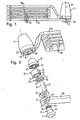
- Figs. 1 to 5 show an inventively designed articulated lock.
- this articulated bar lock has a lock body 11 to which a joint rod 13a is rigidly fastened.
- On the joint rod 13 a successively four joint rods 13 b and a joint rod 13 c are each pivotally and slightly articulated articulated.
- the joint rod 13c is provided with a clamp 15, of which in the closed state of the lock according to FIG. 1, only one mounting base 17 can be seen.
- a lock cylinder housing 19 has the shape of a hollow truncated cone surrounding a lock cylinder receptacle 21, which serves to receive a lock cylinder, not shown in the figures of a conventional structure.
- the lock cylinder housing 19 also has a lateral Fixierfact 23rd
- a driver part 25 essentially has the shape of a hollow cylinder which surrounds a clamp receptacle 27. On an end face of this hollow cylindrical shape, the driver part 25 has a coupling opening 29 for enabling a coupling with said lock cylinder. At the opposite end face, the lateral surface of the driver part 25 is extended along approximately half the circumference to a protruding driver portion 31 which is sickle-shaped in cross-section (see Fig. 4c and 5c). The driver member 25 also has along a the driver portion 31 opposite portion of the outer circumferential surface a rotary clearance recess 33rd
- a latch 35 has the shape of a circular disk with a circular passage opening 37 and a lateral Anschaussparung 39.
- the passage opening 37 is arranged eccentrically with respect to the circular shape of the bolt 35.
- An adjacent to the passage opening 37 surface portion of the bolt 35 serves as a locking portion 41, as will be explained below.
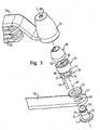
- FIGS. 2 and 3 show that the free end 47 of the joint rod 13c has a fastening opening 49 serving as a gripping device.
- the block 15 has a cylindrical neck neck 51, at one end of the mounting base 17 is formed.
- the other end of the Klobenhalses 51 is formed as a Klobenkopf 53. This is separated from the Klobenhals 51 by a locking recess 55 in the form of a circumferential groove.
- the klobenkopf workede boundary surface of the locking recess 55 forms an annular flat locking portion 57 of the block 15th
- the free end 59 of the joint rod 13 a is inserted into the lock body 11.
- This articulation rod end 59 has a fastening opening 61 serving as encompassing device as well as a fixing opening 63 (compare FIG. 2).
- the lock body 11 is frontally provided with a keyhole 65 (see Fig. 3).
- the lock body 11, the lock cylinder housing 19, the lock cylinder provided therein, the driver part 25, the latch 35, the mounting ring 45 and the clamp 15 are provided in the closed state of the articulated bar lock shown (FIG. 1) for arrangement along a common lock arrangement axis 67.
- the arrangement of the clamp 15 in extension of the provided within the lock cylinder housing 19 lock cylinder characterizes the characteristic linear structure of the lock shown.
- this Schlossanordnurigsachse 67 simultaneously forms the axis of symmetry of the rotationally symmetrical Klobenhalses 51 with the locking recess 55 of the block 15.
- the Schlossan effetivesachse 67 coincides with the Drehbetuschistsachse - not shown in the figures - lock cylinder, and they also corresponds to the axis of rotation of the driver 25, as will be explained below.
- the lock cylinder housing 19 With the locking cylinder not shown in the figures, further the driver part 25 and the bolt 35 along the lock assembly axis 67 within the lock body 11 and there due to the introduced laterally into the lock body 11 hinge rod end 59 of the joint rod 13a caught.
- This joint rod 13a in turn is fixed in the lock body 11 by the fixing pin 43 against a lateral removal from the lock body 11.
- the fixing pin 43 is inserted through the fixing opening 63 of the joint rod 13a, through the Anlenkaussparung 39 of the bolt 35 and through the rotary clearance recess 33 of the driver 25 in the Fixierfact 23 of the lock cylinder housing 19.
- the fixing pin 43 thus also secures the lock cylinder housing 19 against rotation about the lock arrangement axis 67.
- the clamp 15 is fixed to the end 47 of the hinge rod 13c, namely by the Klobenhals 51 is guided through the mounting hole 49 and the mounting base 17 thus abuts against the hinge rod 13c.
- On the opposite side of the hinge rod end 47 of the mounting ring 45 is fixed - for example, by a radial constriction - on the Klobenhals 51, so that the block is caught in the mounting hole 49.
- the mounting base 17 and the fastening ring 45 are spaced apart from each other in such a way that the joint rod 13c is axially displaceable relative to the clamp 15 and / or slightly pivotable with respect to the lock arrangement axis 23. This facilitates the handling of the bracket. If the block 15, as shown in Fig.
- the articulated bar lock shown in FIGS. 1 to 5 functions as follows:
- the clamp 15 can be removed from the clamp receptacle 27 along the lock arrangement axis 67.
- the hingedly connected joint rods 13a, 13b, 13c can then be guided around or through an object to be secured, for example a bicycle.
- the hinge rod 13c is then guided back to the lock body 11 to insert the clamp 15 along the lock assembly axis 67 into the clamp receiver 27.
- the block 15 is locked in this position, as will be explained below.
- the operation of the articulated bar lock shown thus corresponds substantially to that of, for example, a cable lock, the hinge rods serve as a lock bracket.
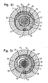
- the latch 35 can be brought into a release position, as shown in Fig. 4a, 4b, 4c.
- this release position the passage opening 37 of the bolt 35 with respect to the Klobenfact 27 of the Mit Converseteils 25 and with respect to the mounting hole 61 of the hinge rod end 59 is aligned such that the Klobenfact 27 extended to a cylindrical cavity and thus released for receiving the block 15 with the Klobenkopf 53 is.
- the bolt 35 is moved perpendicular to the lock assembly axis 67, so that it partially protrudes into the Klobenage 27 and its axial extension and thus also in the locking recess 55 of the block 15 engages (see Fig. 5a, 5b, 5c). This transfer of the bolt 35 in the locking position is done as follows:
- the lock cylinder is rotationally actuated.
- a rotary drive member of the lock cylinder which engages in the coupling opening 29 of the driver 25, is rotated about the lock assembly axis 67.
- the driver member 25 is rotatably supported, namely by the end faces of the driver 25 on the lock cylinder housing 19 and the hinge rod end 59 and the outer circumferential surface of the driver 25 on the inner surface of the Rest against the lock body 11. This rotational actuation of the driver 15 is not hindered by the fixing pin 43, since this is within the rotary clearance recess 33.
- the driver part 25 transmits this rotational movement to the bolt 35 in such a way that it performs a curve / rotational movement within a plane perpendicular to the lock arrangement axis 67.
- a portion of the peripheral end face of the disk-shaped bolt 35 is provided as a driver portion 71, with which cooperates the inner peripheral side of the crescent-shaped cam portion 31 of the driver part 25.
- the latch 35 is movably mounted within the plane perpendicular to the lock arrangement axis 67.
- the latch 35 is moved to the locking position by the driver member 25 performs a rotation about the lock assembly axis 67, which extends in the clockwise direction with respect to the representation of FIG. 4c and 5c.
- the driver portion 31 of the driver 25 moves along along the driver portion 71 on the outer circumference of the bolt 35 and thereby forces the latch 35 to a locking movement in which the latch 35 pivots counterclockwise about one to the fixing pin 35 and the other from the fixing pin 43 radially away, so that the Anlenkaussparung 39 partially disengaged from the fixing pin 43.
- FIGS. 5a and 5b shows the latching position of the bolt 35 achieved thereby.
- the passage opening 37 of the bolt 35 is now offset with respect to the lock arrangement axis 67 and thus with respect to the block 15.
- the latch 35 engages in a part of the locking recess 55 of the Klobens 15 one.
- the locking portion 41 of the bolt 35 which runs perpendicular to the lock arrangement axis 67, bears against the annular locking portion 57 of the bolt 15 (compare FIGS. 5a and 5b).
- the block 15 is thus secured against removal from the Klobenfact 27.
- the renewed release of the block 15 takes place in the reverse order, namely by the lock cylinder is actuated in the reverse direction of rotation and moves the latch 35 via the driver part 25 back into the release position shown in Fig. 4c.
- a particular advantage of the illustrated locking of the clamp 15 within the clamp receptacle 27 is that in the locking position of the bolt 35 whose locking portion 41 flat with the locking portion 57 of the block 15 cooperates, as shown in Fig. 5a and 5b.
- tensile forces are transmitted uniformly - and not only at points or along contact lines - to the bolt 35 and thus to the lock body 11.
- the articulated bar lock shown has a particularly high tensile stability with respect to an attempt to forcibly remove the clamp 15 along the lock assembly axis 67 of the lock body 11. In such a tensile load of the bolt 35 and the cloche head 53 are only subjected to shearing, so that particularly high tensile forces needed to force a yielding of the bolt 35 or the cloche head 53 by force.
- the surface cooperation of the lock sections 41, 57 can be brought about without requiring any axial clearance along the lock arrangement axis 67 for the clamp 15 is that could simplify the attachment of a riser tool, for example between the mounting ring 45 of the block 15 and the ring receiver 69 of the lock body 11 and therefore undesirable.
- Another particular advantage of the illustrated articulated bar lock consists in the manner of attachment of the joint rods 13a and 13c to the lock body 11 and the block 15. As soon as the block 15 is inserted into the lock body 11 and locked therein, embrace the ends 59, 47 both Joint rods 13a, 13c the Klobenhals 51.
- the joint rod end 47 of the joint rod 13c is namely, as explained, by means of the mounting ring 45 permanently attached to the clamp 15.
- the hinge rod end 59 of the hinge rod 13 a is attached to the lock body 11 in such a manner that the cock neck 51 penetrates the attachment hole 61 when the clamp 15 is inserted into the clamp receiver 27.
- This double encompassing of the block 15 by the joint rods 13a, 13c has the advantage that in the case of an attack tensile load of the lock bars formed by the joint rods 13, 13b and 13c, this load is ultimately transferred mainly to the block 15 and the neck 51, respectively.
- excessive loading of the locking mechanism, in particular of the bolt 35 and the driver part 25 is avoided and prevents corresponding damage to the locking of the articulated bar lock.
- the articulated bar lock shown in FIGS. 1 to 5 is designed such that the articulated rod 13a is fastened to the lock body 11 in the position shown in the figures by means of the fixing pin 43 for a service load in the normal operation of the lock. Only with excessive load on the hinge rod 13a, particularly in attempting to forcefully break or wind the lock bracket formed by the hinge rods 13a, 13b and 13c, the hinge rod 13a may move laterally due to slight bending of the fixing pin 43, so that the boundary surface of the attachment hole 61 comes to rest on the neck of the neck 51 and the further tensile load of the joint rod 13a is transmitted directly to the block 15.
- the bolt 35 may also be composed of a plurality of disc-shaped locking elements, which have the same outline as the bolt 35 shown in the figures and arranged parallel to each other adjacent, in particular are attached to each other. In this way, a reinforced locking arrangement can be formed with an even higher shear stability, wherein the individual locking elements can still be manufactured as stampings according to a simple manufacturing process.
- a positive lock is realized. This means that only by corresponding actuation of the lock cylinder by means of the associated identification means of the latch 35 is moved from the release position to the locking position and vice versa.
- an automatic function may be provided, in which the movement of the bolt 35 from the locking position to the release position by the lock cylinder associated with the identification means is triggered, the movement of the bolt 35 in the locked position, however - without the presence of the identification means - by introducing the clamp 15 can be brought into the Klobenfact 27 against the bias by a spring.
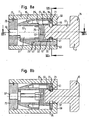
- Fig. 6 to 8 show a mortise lock, which corresponds to the articulated bar lock according to FIGS. 1 to 5 with regard to the construction of its locking mechanism. Similar components as in the illustrated articulated bar lock are marked with the same reference numerals.
- the mortise lock according to FIGS. 6 to 8 - for example as a brake disc lock - has a clamp 15 without hinge rods 13a, 13b, 13c and without any other lock bracket.
- the closure of the lock body 11 takes place at the end facing the clamp 15 by a radially inwardly directed constriction of the ring receptacle 69.
- the lock body 11 is closed by a closing plate 73 which on the lock body 11 by a snap ring 75th is secured.
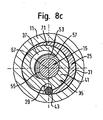
- Fig. 8a, 8b, 8c show the locking position of the bolt 35, corresponding to Fig. 5a, 5b, 5c.
Landscapes
- Lock And Its Accessories (AREA)
- Actuator (AREA)
- Clamps And Clips (AREA)
- Pharmaceuticals Containing Other Organic And Inorganic Compounds (AREA)
- Hydrogenated Pyridines (AREA)
- Vehicle Body Suspensions (AREA)
Abstract
Description
Die Erfindung betrifft ein Schloss, insbesondere ein Zweiradschloss, das zumindest einen Schlosskörper und einen daran verriegelbaren Kloben aufweist, wobei der Schlosskörper einen Schließzylinder, einen mit dem Schließzylinder - zumindest indirekt - gekoppelten Riegel und eine Klobenaufnahme besitzt, in die der Kloben einführbar oder aus der der Kloben entnehmbar ist, und wobei der Schließzylinder und der in der Klobenaufnahme befindliche Kloben entlang einer gemeinsamen Schlossanordnungsachse angeordnet sind.The invention relates to a lock, in particular a two-wheel lock, having at least one lock body and a lockable thereto, the lock body has a lock cylinder, with the lock cylinder - at least indirectly - coupled latch and a Klobenaufnahme, into which the block inserted or out of the the block is removable, and wherein the lock cylinder and located in the Klobenaufnahme block are arranged along a common lock assembly axis.
Dieser Schlosstyp ist also durch eine lineare Anordnung von Schließzylinder und Kloben gekennzeichnet, bei der der Kloben entlang einer Verlängerung des Schließzylinders oder einer Drehbetätigungsachse des Schließzylinders angeordnet ist. Beispielsweise ist es für eine derartige Linearanordnung bekannt, ein an einer Stirnseite des Schließzylinders angeordnetes Drehantriebselement mit einem drehbaren Mitnehmerkäfig zu koppeln. Der Mitnehmerkäfig zwingt, je nach Drehstellung, in einer Lagerungspfanne gelagerte Stahlkugeln zu einem radialen Eintritt in die Klobenaufnahme oder zu einem radialen Zurückweichen aus der Klobenaufnahme. Dadurch wirken die Stahlkugeln zum Verriegeln des Klobens mit einer Umfangsnut am Kloben zusammen bzw. weichen zum Entriegeln aus dieser Umfangsnut zurück. Der Aufbau dieses Schlosses ist unerwünscht aufwändig.This lock type is thus characterized by a linear arrangement of lock cylinder and clamp, wherein the block is arranged along an extension of the lock cylinder or a rotational actuation axis of the lock cylinder. For example, it is known for such a linear arrangement, to couple a arranged at an end face of the lock cylinder rotary drive element with a rotatable carrier cage. The Mitnehmerkäfig forces, depending on the rotational position, stored in a storage pan steel balls to a radial entry into the Klobenaufnahme or to a radial retreat from the Klobenaufnahme. As a result, the steel balls for locking the block cooperate with a circumferential groove on the block or soft for unlocking from this circumferential groove back. The structure of this castle is undesirable consuming.
Aus der US 4,075,878 ist ein Schloss bekannt, bei dem ein Schließzylinder einen Drehriegel zu einer Rotationsbewegung antreibt, wobei der Drehriegel wahlweise in eine Ringnut eines Klobens seitlich eingreift.From US 4,075,878 a lock is known in which a lock cylinder drives a rotary latch to a rotational movement, wherein the rotary latch optionally engages laterally in an annular groove of a block.
Die US 6,055,832 beschreibt ein Schloss mit einem Schließzylinder, einem Drehriegel und einem Kloben, die entlang einer gemeinsamen Schlossanordnungsachse angeordnet sind.US 6,055,832 describes a lock with a lock cylinder, a rotating bolt and a clamp, which are arranged along a common lock assembly axis.
Es ist daher eine Aufgabe der Erfindung, ein Schloss mit der erläuterten Linearanordnung von Schließzylinder und Kloben zu schaffen, das bei einem einfachen und kompakten Aufbau eine hohe Stabilität gegenüber einem gewaltsamen unberechtigten Öffnen besitzt.It is therefore an object of the invention to provide a lock with the illustrated linear arrangement of lock cylinder and block, the at a simple and compact structure has a high stability against a violent unauthorized opening.
Diese Aufgabe wird durch die Merkmale des Anspruchs 1 gelöst.This object is solved by the features of claim 1.
Bei dem erfindungsgemäßen Schloss ist also seitens des Klobens und seitens des Riegels jeweils wenigstens ein flächiger Verriegelungsabschnitt vorgesehen. Für ein Verriegeln des Klobens in der Klobenaufnahme des Schlosskörpers wirken diese Verriegelungsabschnitte flächig zusammen, beispielsweise indem sie aneinander anliegen oder einander gegenüberstehen. Dieses flächige Zusammenwirken erfolgt entlang einer quer, insbesondere senkrecht zu der Schlossanordnungsachse verlaufenden Ebene.In the case of the lock according to the invention, in each case at least one flat locking section is provided on the part of the block and on the side of the bolt. For locking the block in the clamp receiver of the lock body, these locking sections cooperate flatly, for example by abutting one another or facing one another. This surface interaction takes place along a transverse plane, in particular perpendicular to the lock arrangement axis.
Dieser Ausgestaltung liegt die Erkenntnis zugrunde, dass ein flächiges Zusammenwirken von Riegel und Kloben eine besonders hohe Zugstabilität bezüglich eines Versuchs einer gewaltsamen Entnahme des verriegelten Klobens aus der Klobenaufnahme bewirkt. Aufgrund der flächigen Ausgestaltung des Verriegelungsabschnitts des Klobens und des Verriegelungsabschnitts des Riegels kann bei dem gegenseitigen Verriegelungseingriff nämlich eine hohe Flächenabdeckung verwirklicht werden. Außerdem werden der Riegel und der Kloben nur auf Abscherung beansprucht. Diese höhere Zugstabilität macht sich insbesondere gegenüber bekannten Schlössern bemerkbar, bei denen zur Verriegelung des Klobens Stahlkugeln an dem Kloben anliegen und somit letztlich lediglich ein punkt- oder linienförmiger Kontakt zwischen dem Kloben und den Kugeln verwirklicht wird.This embodiment is based on the finding that a surface interaction of bolt and clamp causes a particularly high tensile stability with respect to an attempt to forcibly remove the locked block from the clamp receptacle. Due to the flat Design of the locking portion of the block and the locking portion of the bolt can be realized in the mutual locking engagement namely a high area coverage. In addition, the bolt and the clamp are claimed only on shearing. This higher tensile stability is particularly noticeable in comparison to known locks in which steel balls rest on the block for locking the block and thus ultimately only a point or linear contact between the block and the balls is realized.
Da das flächige Zusammenwirken entlang einer quer zu der Schlossanordnungsachse verlaufenden Ebene erfolgt, wird außerdem ein Abgleiten des zugbelasteten Klobens entlang einer schrägen Verriegelungsfläche des Riegels vermieden. Stattdessen ist gewährleistet, dass der Kloben und der Riegel bei einer Zugbelastung entlang der Schlossanordnungsachse im Wesentlichen ausschließlich auf Abscherung beansprucht werden.In addition, since the surface cooperation takes place along a plane extending transversely to the lock arrangement axis, slippage of the tensile load-bearing block along an oblique locking surface of the bolt is avoided. Instead, it is ensured that the clamp and the bolt are subjected to a tensile load along the lock assembly axis substantially exclusively to shearing.
Zu der Erfindung ist noch anzumerken, dass unter einer quer zu der Schlossanordnungsachse verlaufenden Richtung eine solche Richtung zu verstehen ist, die senkrecht oder im Wesentlichen senkrecht, insbesondere schräg zu der Schlossanordnungsachse verläuft.It should also be noted with the invention that a direction running transversely to the lock arrangement axis is to be understood as meaning a direction which is perpendicular or substantially perpendicular, in particular oblique to the lock arrangement axis.
Gemäß einer bevorzugten Ausführungsform der Erfindung erfolgt die Bewegung des Riegels zwischen der Freigabestellung und der Verriegelungsstellung entlang einer Richtung quer zu der Schlossanordnungsachse. Dadurch kann das flächige Zusammenwirken der Verriegelungsabschnitte in der Verriegelungsstellung besonders einfach verwirklicht werden. Bei einem üblichen Schlossaufbau treibt nämlich der Schließzylinder ein Mitnehmerteil zu einer Drehbewegung um die Schlossanordnungsachse an. Eine derartige Drehbewegung besitzt tangentiale Bewegungskomponenten, die senkrecht zu der Drehachse und somit zu der Schlossanordnungsachse verlaufen, und die somit auf einfache Weise in eine Riegelbewegung quer zu der Schlossanordnungsachse umgesetzt werden können. Somit kann das erfindungsgemäße Schloss letztlich mit einem kompakten Aufbau einer Mitnehmer- und Verriegelungsmechanik verwirklicht werden.According to a preferred embodiment of the invention, the movement of the bolt between the release position and the locking position takes place along a direction transverse to the lock arrangement axis. As a result, the surface interaction of the locking portions in the locking position can be realized particularly easily. In a conventional lock construction drives namely the lock cylinder a driver part for a rotational movement about the lock assembly axis. Such rotational movement has tangential components of movement which are perpendicular to the axis of rotation and thus to the lock assembly axis, and which thus can be easily translated into a latching movement transverse to the lock assembly axis. Thus, the lock according to the invention can ultimately be realized with a compact design of a driving and locking mechanism.
Weiterhin ist es bevorzugt; wenn der Riegel im Wesentlichen scheibenförmig ausgebildet ist. Durch diese Ausbildung kann der Riegel - beispielsweise als Metallscheibe - auf besonders einfache Weise hergestellt werden, während er gleichzeitig einen flachen und somit kompakten Aufbau besitzen und mit dem erforderlichen flächigen Verriegelungsabschnitt ausgestattet sein kann.Furthermore, it is preferred; when the bar is substantially disc-shaped. By this design, the bolt - for example, as a metal disc - are made in a particularly simple manner, while at the same time have a flat and thus compact design and can be equipped with the required surface locking portion.
Die Bewegung des Riegels zwischen der Verriegelungsstellung und der Freigabestellung kann - je nach Kopplung mit einem Mitnehmerteil und je nach Führung innerhalb des Schlosskörpers- beispielsweise als kurvenförmiges Verschieben, geradliniges Verschieben, Verschwenken, als Drehbewegung um die Schlossanordnungsachse oder als eine Kombination dieser Bewegungsarten erfolgen. Vorzugsweise führt der Riegel eine Kombination aus einer Kurven- und Drehbewegung innerhalb der quer zu der Schlossanordnungsachse verlaufenden Ebene durch.The movement of the bolt between the locking position and the release position can - depending on the coupling with a driver part and depending on leadership within the lock body, for example, as a curved displacement, linear displacement, pivoting, as a rotational movement about the lock assembly axis or as a combination of these types of movement. Preferably, the latch performs a combination of a turning and turning movement within the plane transverse to the lock assembly axis.
Um eine derartige Kurven-/Drehbewegung oder eine reine Schwenkbewegung herbeizuführen, kann der Riegel an einer Gelenkeinrichtung angelenkt sein, die bezüglich der Schlossanordnungsachse vorzugsweise in exzentrischer Anordnung vorgesehen ist.In order to bring about such a curve / rotary movement or a pure pivoting movement, the bolt can be hinged to a hinge device be, which is preferably provided with respect to the lock assembly axis in eccentric arrangement.
Die Freigabeaussparung des Riegels kann durch eine Durchlassöffnung, also eine umfänglich geschlossene Öffnung gebildet sein. Insbesondere für den Fall einer Kurven-/Drehbewegung oder einer Schwenkbewegung des Riegels ist es bevorzugt, wenn die Freigabeaussparung an dem Riegel in einer exzentrischen Anordnung vorgesehen ist. Alternativ zu der Ausbildung als Durchlassöffnung kann die Freigabeaussparung auch durch eine seitliche Einbuchtung des Riegels, beispielsweise nach Art eines Hakens gebildet sein.The release recess of the bolt can be formed by a passage opening, ie a circumferentially closed opening. In particular, in the case of a curve / rotary movement or a pivotal movement of the bolt, it is preferred if the release recess is provided on the bolt in an eccentric arrangement. As an alternative to the embodiment as a passage opening, the release recess can also be formed by a lateral indentation of the bolt, for example in the manner of a hook.
Hinsichtlich des Antriebs des Riegels ist es bevorzugt, wenn das Schloss ein Mitnehmerteil aufweist, über das der Riegel mit dem Schließzylinder gekoppelt ist. Vorzugsweise weist der Riegel einen Mitnehmerabschnitt auf, an dem das Mitnehmerteil angreift, um den Riegel zu einer Bewegung in die Verriegelungsstellung und/oder in die Freigabestellung anzutreiben. Der Riegel und das Mitnehmerteil sind insbesondere dergestalt gekoppelt, dass eine Drehbewegung des Mitnehmerteils um die Schlossanordnungsachse in eine Bewegung des Riegels quer zu der Schlossanordnungsachse umgesetzt wird. Der Mitnehmerabschnitt des Riegels kann beispielsweise durch eine Stirnseite des Riegels oder - für eine Kulissenführung - eine Eingriffsnut gebildet sein, die vorzugsweise innerhalb einer quer zu der Schlossanordnungsachse verlaufenden Ebene verläuft.With regard to the drive of the bolt, it is preferred if the lock has a driver part, via which the bolt is coupled to the lock cylinder. Preferably, the latch on a driver portion on which the driver member engages to drive the latch to move to the locking position and / or in the release position. In particular, the latch and the driver member are coupled such that rotational movement of the driver member about the latch assembly axis translates into movement of the latch transverse to the latch assembly axis. The driver portion of the bolt may for example be formed by an end face of the bolt or - for a slotted guide - an engagement groove, which preferably extends within a transverse plane to the lock assembly axis.
Ferner ist es bevorzugt, wenn das genannte Mitnehmerteil für die Kopplung mit dem Riegel wenigstens einen Mitnehmerabschnitt aufweist, der insbesondere sichelförmig ausgebildet ist. Eine derartige Sichel- oder Halbmondform ist besonders geeignet, um - durch Zusammenwirken mit einem Mitnehmerabschnitt des Riegels - den Riegel zu einer exzentrischen Dreh- oder Schwenkbewegung anzutreiben. Allerdings können zu diesem Zweck auch ein oder mehrere Mitnehmerzapfen, -nocken oder -stifte vorgesehen sein, die an einem Mitnehmerabschnitt des Riegels angreifen.Furthermore, it is preferred if the said driver part for the coupling with the bolt has at least one driver section, which is in particular designed sickle-shaped. Such a sickle or Crescent shape is particularly suitable for driving the latch to an eccentric pivoting or pivoting motion through cooperation with a catch portion of the latch. However, for this purpose, one or more driving pins, cams or pins may be provided, which engage a driver portion of the bolt.
Der Kopplungseingriff zwischen Mitnehmerteil und Riegel kann auch umgekehrt ausgebildet sein, so dass letztlich eine Mitnehmererhöhung des Riegels in eine Mitnehmervertiefung des Mitnehmerteils eingreift.The coupling engagement between driver part and latch can also be configured in reverse, so that ultimately a driver increase of the bolt engages in a driver recess of the driver part.
Gemäß einer bevorzugten Weiterbildung der Erfindung weist das Schloss einen Bügel auf, wobei ein klobenseitiges Bügelende mit dem Kloben verbunden und ein schlosskörperseitiges Bügelende eine Umgreifungseinrichtung aufweist, die dergestalt an dem Schlosskörper angeordnet ist, dass sie den Kloben hintergreift oder umfänglich umgreift, falls der Kloben in die Klobenaufnahme eingeführt ist.According to a preferred embodiment of the invention, the lock on a bracket, wherein a klobenseitiges bracket end connected to the clamp and a lock body side bracket end has a clasping, which is arranged on the lock body such that it engages behind the block or circumferentially engages around, if the block in the Klobenaufnahme is introduced.
Mit anderen Worten ist ein Bügel vorgesehen, der mit einem Ende am Schlosskörper befestigt ist und dessen freies Ende mittels des Klobens wahlweise an dem Schlosskörper verriegelt werden kann, beispielsweise um einen mittels des Bügels umgriffenen Gegenstand gegen ein Entfernen zu sichern. Die erläuterte Anordnung bewirkt eine besonders stabile Verbindung des schlosskörperseitigen Bügelendes mit dem Kloben im Falle einer gewaltsamen Zugbelastung. Dabei kann ein Umgreifen des Klobens entlang eines geschlossenen Umfangs vorgesehen sein, beispielsweise indem die Umgreifungseinrichtung eine Öse eines Gelenkstabbügels oder eines Starrbügels, oder eine Schlaufe eines Panzerkabelbügels oder eines Seilbügels aufweist. Alternativ hierzu kann ein Hintergreifen entlang eines geöffneten Umfangs erfolgen, also nach Art eines Hakens.In other words, a bracket is provided, which is fastened with one end to the lock body and the free end of which can be selectively locked by means of the clamp on the lock body, for example, to secure an embraced by means of the bracket object against removal. The arrangement explained causes a particularly stable connection of the lock body side bracket end with the clamp in the event of a violent tensile load. In this case, a gripping around the clamp along a closed circumference may be provided, for example by the Umgreifungseinrichtung an eyelet of a Gelenkstabbügels or a Starrbügels, or a loop of a Panzerkabelbügels or having a cable bracket. Alternatively, a gripping behind along an open circumference can take place, so in the manner of a hook.
Dieser Weiterbildung liegt die Erkenntnis zugrunde, dass in vielen Fällen des gewaltsamen Aufbrechens eines Schlossbügels die Schwachstelle an der Verbindung der Bügelenden am Schlosskörper liegt, da eine Angriffszugbelastung des Bügels auf diese Verbindung übertragen wird und dort - trotz Verriegelung des Klobens am Schlosskörper - zu einem unerwünschten Lösen der Verbindung der Bügelenden führen kann.This development is based on the finding that in many cases the violent breaking of a lock strap, the weak point at the connection of the strap ends on the lock body, as a Angriffszugbelastung the bracket is transmitted to this connection and there - despite locking the block on the lock body - to an undesirable Loosening the connection of the temple ends can lead.
Da bei der erläuterten Weiterbildung im Falle eines gewaltsamen Auseinanderziehens des Bügels letztlich beide Bügelenden an dem Kloben angreifen, wird eine derartige Angriffszugbelastung hauptsächlich oder ausschließlich auf den Kloben übertragen, der massiv und besonders stabil ausgebildet sein kann. Demgegenüber wird eine derartige Angriffszugbelastung des Bügels nicht oder lediglich in geringem Maße auf einen Verriegelungsmechanismus des Schlosses übertragen, so dass dieser durch ein gewaltsames Auseinanderziehen des Bügels nicht leicht beschädigt wird.Since in the described embodiment, in the event of a violent pulling apart of the strap, both strap ends ultimately engage the clamp, such an attack pull load is transmitted mainly or exclusively to the clamp, which can be solid and particularly stable. In contrast, such a Zugszugbelastung the strap is not or only slightly transferred to a locking mechanism of the castle, so that it is not easily damaged by a violent pulling apart of the bracket.
Da eine Angriffszugbelastung am Bügel kaum auf den Verriegelungsmechanismus des Schlosses übertragen wird, ist ferner ein vergleichsweise kompakter Aufbau des Verriegelungsmechanismus und somit des Schlosskörpers möglich.Since an attack tension load on the bracket is hardly transmitted to the locking mechanism of the lock, a comparatively compact construction of the locking mechanism and thus of the lock body is also possible.
Für die erläuterte Weiterbildung ist es nicht zwingend erforderlich, dass während des normalen, berechtigten Gebrauchs des Schlosses das schlosskörperseitige Bügelende stets an dem Kloben anliegt. Stattdessen ist es zur Erzielung der erläuterten vorteilhaften Belastungsübertragung auf den Kloben lediglich erforderlich, dass das schlosskörperseitige Bügelende im Falle einer Angriffszugbelastung des Bügels am Kloben angreift. Zu diesem Zweck ist es bevorzugt, dass während einer normalen, berechtigten Gebrauchsbelastung des Bügels das schlosskörperseitige Bügelende starr an dem Schlosskörper befestigt ist. Alternativ hierzu ist es jedoch auch möglich, dass das schlosskörperseitige Bügelende an dem Schlosskörper beweglich, beispielsweise verschiebbar befestigt ist, so dass dieses Bügelende im Falle jeglicher Zugbelastung des Bügels sofort am Kloben angreift, sofern dieser in die Klobenaufnahme eingeführt ist.For the described development, it is not absolutely necessary that during the normal, legitimate use of the castle, the lock body side bracket end always rests against the block. Instead it is to achieve the described advantageous load transfer to the block only required that the lock body side bracket end attacks in the event of a Angriffszugbelastung the bracket on the block. For this purpose, it is preferred that during a normal, legitimate use load of the bracket, the lock body side bracket end is rigidly secured to the lock body. Alternatively, however, it is also possible that the lock body-side end bracket is movably attached to the lock body, for example, slidably, so that this strap end in the event of any tensile load of the strap immediately attacks the block, if this is introduced into the Klobenaufnahme.
Bei dem genannten Bügel kann es sich beispielsweise um ein Seil, ein Panzerkabel, eine Kette, einen Stabbügel oder einen Gelenkstabbügel handeln.The said bracket may be, for example, a cable, a catenary cable, a chain, a rod bracket or a Gelenkstabbügel.
Vorzugsweise sind das klobenseitige und das schlosskörperseitige Bügelende dergestalt an dem Kloben bzw. dem Schlosskörper befestigt, dass die Bügelenden bei einer Angriffszugbelastung des Bügels in einander entgegengesetzter Richtung, insbesondere diametral entgegengesetzt an dem Kloben angreifen, sofern der Kloben sich in der Klobenaufnahme befindet. Bei einer derartigen Ausgestaltung kann die Angriffszugbelastung besonders wirkungsvoll von dem Kloben aufgenommen werden, so dass das Schloss besonders stabil gegenüber einem gewaltsamen Öffnen des Bügels ist.Preferably, the clip-side and the lock-body side bracket end are attached to the block or lock body in such a way that the strap ends engage in an opposing pull of the bracket in opposite directions, in particular diametrically opposite to the block, provided the block is in the block receiver. In such an embodiment, the attack tensile load can be particularly effectively absorbed by the block, so that the lock is particularly stable against a violent opening of the bracket.
Bei der erläuterten Weiterbildung ist es möglich, dass das klobenseitige Bügelende mit einem separaten Kloben dauerhaft verbunden oder mit einem Kloben einstückig ausgebildet ist. Es ist jedoch bevorzugt, wenn auch das klobenseitige Bügelende eine Umgreifungseinrichtung aufweist, die den Kloben in einer Weise hintergreift oder umfänglich umgreift, wie im Zusammenhang mit dem schlosskörperseitigen Bügelende bereits erläutert.In the illustrated embodiment, it is possible that the cloverleaf end of the strap is permanently connected to a separate block or formed integrally with a clamp. However, it is preferred if Also, the claw-side bracket end has a clasping device which engages behind the claw in a manner or circumferentially surrounds, as already explained in connection with the lock body side bracket end.
Weitere Ausführungsformen der Erfindung sind in den Unteransprüchen genannt. Die Erfindung wird nachfolgend beispielhaft unter Bezugnahme auf die Zeichnungen erläutert; in diesen zeigen:
- Fig. 1
- eine Seitenansicht eines erfindungsgemäßen Gelenkstabschlosses,
- Fig. 2 und 3
- jeweils eine Explosionsdarstellung dieses Schlosses,
- Fig. 4a, 4b und 4c
- Querschnittsansichten dieses Schlosses in der Freigabestellung entlang einer Längsmittenebene, entlang der Ebene IVb-IVb bzw. entlang der Ebene IVc-IVc,
- Fig. 5a, 5b und 5c
- Querschnittsansichten dieses Schlosses in der Verriegelungsstellung entlang einer Längsmittenebene, entlang der Ebene Vb-Vb bzw. entlang der Ebene Vc-Vc,
- Fig. 6 und 7
- Explosionsdarstellungen eines erfindungsgemäßen Klobenschlosses,
- Fig. 8a, 8b und 8c
- Querschnittsansichten dieses Schlosses in der Verriegelungsstellung entlang einer Längsmittenebene, entlang der Ebene VIIIb-VIIIb bzw. entlang der Ebene VIIIc-VIIIc.
- Fig. 1
- a side view of a hinged bar lock according to the invention,
- FIGS. 2 and 3
- each an exploded view of this castle,
- Fig. 4a, 4b and 4c
- Cross-sectional views of this lock in the release position along a longitudinal center plane, along the plane IVb-IVb and along the level IVc-IVc,
- Fig. 5a, 5b and 5c
- Cross-sectional views of this lock in the locking position along a longitudinal center plane, along the plane Vb-Vb and along the plane Vc-Vc,
- 6 and 7
- Exploded views of a mortise lock according to the invention,
- Fig. 8a, 8b and 8c
- Cross-sectional views of this lock in the locking position along a longitudinal center plane, along the plane VIIIb-VIIIb and along the plane VIIIc-VIIIc.
Die Fig. 1 bis 5 zeigen ein erfindungsgemäß ausgebildetes Gelenkstabschloss. Wie aus der Seitenansicht gemäß Fig. 1 ersichtlich, besitzt dieses Gelenkstabschloss einen Schlosskörper 11, an dem ein Gelenkstab 13a starr befestigt ist. An dem Gelenkstab 13a sind nacheinander vier Gelenkstäbe 13b sowie ein Gelenkstab 13c jeweils schwenkbar und geringfügig abwinkelbar angelenkt. Der Gelenkstab 13c ist mit einem Kloben 15 versehen, von dem im geschlossenen Zustand des Schlosses gemäß Fig. 1 lediglich ein Befestigungssockel 17 ersichtlich ist.Figs. 1 to 5 show an inventively designed articulated lock. As can be seen from the side view of FIG. 1, this articulated bar lock has a
Die im Folgenden erläuterten Bestandteile des Gelenkstabschlosses gemäß Fig. 1 sowie deren jeweilige Ausgestaltung sind insbesondere aus den Explosionsdarstellungen gemäß Fig. 2 und 3 ersichtlich.The constituents of the articulated bar lock according to FIG. 1 explained below and their respective configuration can be seen in particular from the exploded views according to FIGS. 2 and 3.
Ein Schließzylindergehäuse 19 besitzt die Form eines Hohlkegelstumpfes, der eine Schließzylinderaufnahme 21 umgibt, die zur Aufnahme eines in den Figuren nicht gezeigten Schließzylinders eines üblichen Aufbaus dient. Das Schließzylindergehäuse 19 besitzt ferner eine seitliche Fixieraufnahme 23.A
Ein Mitnehmerteil 25 besitzt im Wesentlichen die Form eines Hohlzylinders, der eine Klobenaufnahme 27 umgibt. An einer Stirnseite dieser Hohlzylinderform besitzt das Mitnehmerteil 25 eine Kopplungsöffnung 29 zur Ermöglichung einer Kopplung mit dem genannten Schließzylinder. An der gegenüberliegenden Stirnseite ist die Mantelfläche des Mitnehmerteils 25 entlang ungefähr des halben Umfangs zu einem überstehenden Mitnehmerabschnitt 31 verlängert, der im Querschnitt sichelförmig ist (vgl. Fig. 4c und 5c). Das Mitnehmerteil 25 besitzt außerdem entlang eines dem Mitnehmerabschnitt 31 gegenüberliegenden Abschnitts der Außenmantelfläche eine Drehspielaussparung 33.A
Ein Riegel 35 besitzt die Form einer kreisrunden Scheibe mit einer kreisrunden Durchlassöffnung 37 und einer seitlichen Anlenkaussparung 39. Die Durchlassöffnung 37 ist bezüglich der Kreisform des Riegels 35 exzentrisch angeordnet.A
Ein an die Durchlassöffnung 37 angrenzender Flächenabschnitt des Riegels 35 dient als Verriegelungsabschnitt 41, wie nachstehend noch erläutert wird.An adjacent to the
Ferner sind ein längszylindrischer Fixierstift 43 sowie ein Befestigungsring 45 vorgesehen. Außerdem zeigen Fig. 2 und 3, dass das freie Ende 47 des Gelenkstabs 13c eine als Umgreifungseinrichtung dienende Befestigungsöffnung 49 besitzt.Furthermore, a longitudinal
Der Kloben 15 besitzt einen zylindrischen Klobenhals 51, an dessen einem Ende der Befestigungssockel 17 angeformt ist. Das andere Ende des Klobenhalses 51 ist als ein Klobenkopf 53 ausgebildet. Dieser ist vom Klobenhals 51 durch eine Verriegelungsaussparung 55 in der Form einer Umfangsnut getrennt. Die klobenkopfseitige Begrenzungsfläche der Verriegelungsaussparung 55 bildet einen ringförmigen flächigen Verriegelungsabschnitt 57 des Klobens 15.The
In der Darstellung gemäß Fig. 2 und 3 ist das freie Ende 59 des Gelenkstabs 13a in den Schlosskörper 11 eingeführt. Dieses Gelenkstabende 59 besitzt eine als Umgreifungseinrichtung dienende Befestigungsöffnung 61 sowie eine Fixieröffnung 63 (vgl. Fig. 2). Außerdem ist der Schlosskörper 11 stirnseitig mit einem Schlüsselloch 65 versehen (vgl. Fig. 3).In the illustration according to FIGS. 2 and 3, the
Der Schlosskörper 11, das Schließzylindergehäuse 19, der darin vorgesehene Schließzylinder, das Mitnehmerteil 25, der Riegel 35, der Befestigungsring 45 und der Kloben 15 sind im geschlossenen Zustand des gezeigten Gelenkstabschlosses (Fig. 1) zur Anordnung entlang einer gemeinsamen Schlossanordnungsachse 67 vorgesehen. Insbesondere die Anordnung des Klobens 15 in Verlängerung des innerhalb des Schließzylindergehäuses 19 vorgesehenen Schließzylinders kennzeichnet den charakteristischen Linearaufbau des gezeigten Schlosses. Wie aus Fig. 2 und 3 ersichtlich, bildet diese Schlossanordnurigsachse 67 gleichzeitig die Symmetrieachse des rotationssymmetrisch ausgebildeten Klobenhalses 51 mit der Verriegelungsaussparung 55 des Klobens 15. Ferner fällt die Schlossanordnungsachse 67 mit der Drehbetätigungsachse des - in den Figuren nicht gezeigten - Schließzylinders zusammen, und sie entspricht ferner der Drehachse des Mitnehmerteils 25, wie nachfolgend noch erläutert wird.The
Fig. 4 und 5 zeigen die Anordnung der genannten Bauteile im montierten und geschlossenen Zustand des Gelenkstabschlosses, und zwar für eine Freigabestellung bzw. eine Verriegelungsstellung des Riegels 35.4 and 5 show the arrangement of said components in the assembled and closed state of the articulated bar lock, for a release position and a locking position of the bolt 35th
Im montierten Zustand sind das Schließzylindergehäuse 19 mit dem darin befindlichen, in den Figuren nicht gezeigtem Schließzylinder, ferner das Mitnehmerteil 25 und der Riegel 35 entlang der Schlossanordnungsachse 67 innerhalb des Schlosskörpers 11 angeordnet und dort aufgrund des seitlich in den Schlosskörper 11 eingeführten Gelenkstabendes 59 des Gelenkstabs 13a gefangen. Dieser Gelenkstab 13a wiederum ist im Schlosskörper 11 durch den Fixierstift 43 gegen eine seitliche Entnahme aus dem Schlosskörper 11 fixiert. Der Fixierstift 43 ist durch die Fixieröffnung 63 des Gelenkstabs 13a, durch die Anlenkaussparung 39 des Riegels 35 und durch die Drehspielaussparung 33 des Mitnehmerteils 25 in die Fixieraufnahme 23 des Schließzylindergehäuses 19 eingesetzt. Der Fixierstift 43 sichert somit außerdem das Schließzylindergehäuse 19 gegen ein Verdrehen um die Schlossanordnungsachse 67.In the assembled state, the
Der Kloben 15 ist an dem Ende 47 des Gelenkstabs 13c befestigt, und zwar indem der Klobenhals 51 durch die Befestigungsöffnung 49 geführt ist und der Befestigungssockel 17 somit an dem Gelenkstab 13c anliegt. An der gegenüberliegenden Seite des Gelenkstabendes 47 ist der Befestigungsring 45 - beispielsweise durch eine radiale Einschnürung - an dem Klobenhals 51 fixiert, so dass der Kloben in der Befestigungsöffnung 49 gefangen ist. Der Befestigungssockel 17 und der Befestigungsring 45 sind dergestalt voneinander beabstandet, dass der Gelenkstab 13c bezüglich des Klobens 15 axial verschiebbar und/oder bezüglich der Schlossanordnungsachse 23 geringfügig verschwenkbar ist. Dies erleichtert die Handhabung des Bügels. Sofern der Kloben 15, wie in Fig. 4a, 4b, 5a und 5b gezeigt, mit dem Klobenkopf 53 in die Klobenaufnahme 27 des Mitnehmerteils 25 eingeführt ist, bildet der Befestigungsring 45 einen Formschluss mit einer Ringaufnahme 69, die durch die ringförmige Stirnseite des Schlosskörpers 11 gebildet ist.The
Das in Fig. 1 bis 5 gezeigte Gelenkstabschloss funktioniert wie folgt:The articulated bar lock shown in FIGS. 1 to 5 functions as follows:
Falls der Riegel 35 sich in der Freigabestellung befindet (Fig. 4a, 4b und 4c) kann der Kloben 15 aus der Klobenaufnahme 27 entlang der Schlossanordnungsachse 67 entnommen werden. Die schwenkbar miteinander verbundenen Gelenkstäbe 13a, 13b, 13c können dann um bzw. durch ein zu sicherndes Objekt, beispielsweise ein Fahrrad, geführt werden. Der Gelenkstab 13c wird dann wieder an den Schlosskörper 11 geführt, um den Kloben 15 entlang der Schlossanordnungsachse 67 in die Klobenaufnahme 27 einzuführen. Schließlich wird der Kloben 15 in dieser Position verriegelt, wie nachfolgend erläutert wird. Die Funktionsweise des gezeigten Gelenkstabschlosses entspricht somit im Wesentlichen derjenigen beispielsweise eines Seilschlosses, wobei die Gelenkstäbe als Schlossbügel dienen.If the
Die Verriegelung des Klobens 15 an dem gezeigten Schloss geschieht folgendermaßen:The locking of the
Der Riegel 35 kann in eine Freigabestellung gebracht werden, wie in Fig. 4a, 4b, 4c gezeigt. In dieser Freigabestellung ist die Durchlassöffnung 37 des Riegels 35 bezüglich der Klobenaufnahme 27 des Mitnehmerteils 25 und bezüglich der Befestigungsöffnung 61 des Gelenkstabendes 59 derart ausgerichtet, dass die Klobenaufnahme 27 zu einem zylindrischen Hohlraum verlängert und somit für die Aufnahme des Klobens 15 mit dem Klobenkopf 53 freigegeben ist. Um den Kloben 15 in dieser Position zu verriegeln, wird der Riegel 35 senkrecht zu der Schlossanordnungsachse 67 bewegt, so dass er teilweise in die Klobenaufnahme 27 bzw. deren axiale Verlängerung hineinragt und somit auch in die Verriegelungsaussparung 55 des Klobens 15 eingreift (vgl. Fig. 5a, 5b, 5c). Dieses Überführen des Riegels 35 in die Verriegelungsstellung geschieht folgendermaßen:The
Mittels eines Schlüssels oder eines sonstigen Identmittels, das durch das Schlüsselloch 65 des Schlosskörpers 11 in den im Schließzylindergehäuse 19 befindlichen Schließzylinder eingeführt wird, wird der Schließzylinder drehbetätigt. Dadurch wird ein Drehantriebselement des Schließzylinders, das in die Kopplungsöffnung 29 des Mitnehmerteils 25 eingreift, um die Schlossanordnungsachse 67 gedreht. Dies führt zu einer Drehbewegung des Mitnehmerteils 25 um die Schlossanordnungsachse 67. Zu diesem Zweck ist das Mitnehmerteil 25 drehbar gelagert, und zwar indem die Stirnseiten des Mitnehmerteils 25 an dem Schließzylindergehäuse 19 bzw. dem Gelenkstabende 59 und die Außenmantelfläche des Mitnehmerteils 25 an der Innenmantelfläche des Schlosskörpers 11 anliegen. Diese Drehbetätigung des Mitnehmerteils 15 wird durch den Fixierstift 43 nicht gehindert, da dieser innerhalb der Drehspielaussparung 33 liegt.By means of a key or other identification means, which is inserted through the
Das Mitnehmerteil 25 überträgt diese Drehbewegung auf den Riegel 35 derart, dass dieser innerhalb einer senkrecht zur Schlossanordnungsachse 67 verlaufenden Ebene eine Kurven-/Drehbewegung vollzieht. Zu diesem Zweck ist ein Abschnitt der Umfangsstirnseite des scheibenförmigen Riegels 35 als Mitnehmerabschnitt 71 vorgesehen, mit dem die Innenumfangsseite des sichelförmigen Mitnehmerabschnitts 31 des Mitnehmerteils 25 zusammenwirkt. Der Riegel 35 ist innerhalb der senkrecht zu der Schlossanordnungsachse 67 verlaufenden Ebene bewegbar gelagert.The
Hierfür liegt er mit einer Seite an der zugewandten Stirnseite des Mitnehmerteils 25 und mit der gegenüberliegenden Seite an dem Gelenkstabende 59 an (vgl. Fig. 4a, 4b, 5a, 5b).For this purpose it lies with one side on the facing end side of the
Fig. 4c und 5c zeigen das Zusammenwirken von Riegel 35 und Mitnehmerteil 25. In der Freigabestellung des Riegels 35 gemäß Fig. 4c ist die Durchlassöffnung 37 des Riegels 35, wie erläutert, bezüglich des Klobens 15 ausgerichtet und somit bezüglich der Schlossanordnungsachse 67 zentriert. Die Anlenkaussparung 39 umgreift dabei den Fixierstift 43. Der sichelförmige Mitnehmerabschnitt 31 des Mitnehmerteils 25 liegt bezüglich des Fixierstifts 43 im Wesentlichen gegenüberstehend an dem Mitnehmerabschnitt 71 des Riegels 35 an.4c and 5c show the cooperation of
Ausgehend von diesem Zustand wird der Riegel 35 in die Verriegelungsstellung bewegt, indem das Mitnehmerteil 25 eine Drehung um die Schlossanordnungsachse 67 durchführt, die bezüglich der Darstellung gemäß Fig. 4c und 5c im Uhrzeigersinn verläuft. Der Mitnehmerabschnitt 31 des Mitnehmerteils 25 fährt dabei entlang des Mitnehmerabschnitts 71 am Außenumfang des Riegels 35 entlang und zwingt den Riegel 35 dadurch zu einer Verriegelungsbewegung, bei der der Riegel 35 zum einen entgegen dem Uhrzeigersinn um den Fixierstift 35 schwenkt und zum anderen sich von dem Fixierstift 43 radial entfernt, so dass die Anlenkaussparung 39 teilweise außer Eingriff mit dem Fixierstift 43 gerät.From this state, the
Fig. 5c zeigt die dadurch erreichte Verriegelungsstellung des Riegels 35. Die Durchlassöffnung 37 des Riegels 35 ist nun bezüglich der Schlossanordnungsachse 67 und somit bezüglich des Klobens 15 versetzt. Dadurch greift der Riegel 35 in einen Teil der Verriegelungsaussparung 55 des Klobens 15 ein. Somit liegt der senkrecht zur Schlossanordnungsachse 67 verlaufende Verriegelungsabschnitt 41 des Riegels 35 an dem ringförmigen Verriegelungsabschnitt 57 des Klobens 15 an (vgl. Fig. 5a und 5b). Der Kloben 15 ist somit gegen eine Entnahme aus der Klobenaufnahme 27 gesichert.5c shows the latching position of the
Das neuerliche Freigeben des Klobens 15 erfolgt in umgekehrter Reihenfolge, nämlich indem der Schließzylinder in umgekehrter Drehrichtung betätigt wird und den Riegel 35 über das Mitnehmerteil 25 zurück in die in Fig. 4c gezeigte Freigabestellung bewegt.The renewed release of the
Ein besonderer Vorteil der erläuterten Verriegelung des Klobens 15 innerhalb der Klobenaufnahme 27 besteht darin, dass in der Verriegelungsstellung des Riegels 35 dessen Verriegelungsabschnitt 41 flächig mit dem Verriegelungsabschnitt 57 des Klobens 15 zusammenwirkt, wie in Fig. 5a und 5b gezeigt. Dadurch werden Zugbelastungskräfte gleichmäßig - und nicht lediglich punktuell oder entlang von Kontaktlinien - auf den Riegel 35 und somit auf den Schlosskörper 11 übertragen. Somit besitzt das gezeigte Gelenkstabschloss eine besonders hohe Zugstabilität bezüglich eines Versuchs einer gewaltsamen Entnahme des Klobens 15 entlang der Schlossanordnungsachse 67 aus dem Schlosskörper 11. Bei einer derartigen Zugbelastung werden der Riegel 35 und der Klobenkopf 53 lediglich auf Abscherung beansprucht, so dass besonders hohe Zugkräfte benötigt werden, um ein Nachgeben des Riegels 35 oder des Klobenkopfes 53 gewaltsam herbeizuführen.A particular advantage of the illustrated locking of the
Von besonderem Vorteil ist es, dass der flächige Verriegelungsabschnitt 41 des Riegels 35 und der flächige Verriegelungsabschnitt 57 des Klobens 15 jeweils senkrecht zu der Schlossanordnungsachse 67 verlaufen, so dass beim Zusammenwirken dieser Verriegelungsabschnitte 41, 57 nicht die Gefahr eines Abgleitens des Klobens an einer Verriegelungsschräge besteht.It is particularly advantageous that the
Indem der Riegel 35 für das Überführen von der Freigabestellung in die Verriegelungsstellung innerhalb einer Ebene senkrecht zu der Schlossanordnungsachse 67 bewegt wird, kann das flächige Zusammenwirken der Verriegelungsabschnitte 41, 57 herbeigeführt werden, ohne dass für den Kloben 15 irgendein axiales Spiel entlang der Schlossanordnungsachse 67 erforderlich ist, das das Ansetzen eines Aufbruchswerkzeugs beispielsweise zwischen dem Befestigungsring 45 des Klobens 15 und der Ringaufnahme 69 des Schlosskörpers 11 vereinfachen könnte und deshalb unerwünscht ist.By moving the
Ein weiterer besonderer Vorteil des erläuterten Gelenkstabschlosses besteht in der Art der Befestigung der Gelenkstäbe 13a und 13c an dem Schlosskörper 11 bzw. dem Kloben 15. Sobald nämlich der Kloben 15 in den Schlosskörper 11 eingeführt und darin verriegelt ist, umgreifen die Enden 59, 47 beider Gelenkstäbe 13a, 13c den Klobenhals 51. Das Gelenkstabende 47 des Gelenkstabs 13c ist nämlich, wie erläutert, mittels des Befestigungsrings 45 dauerhaft an dem Kloben 15 befestigt. Das Gelenkstabende 59 des Gelenkstabs 13a ist dergestalt an dem Schlosskörper 11 befestigt, dass der Klobenhals 51 die Befestigungsöffnung 61 durchdringt, wenn der Kloben 15 in die Klobenaufnahme 27 eingeführt ist.Another particular advantage of the illustrated articulated bar lock consists in the manner of attachment of the
Diese zweifache Umgreifung des Klobens 15 durch die Gelenkstäbe 13a, 13c hat den Vorteil, dass im Falle einer Angriffszugbelastung des durch die Gelenkstäbe 13, 13b und 13c gebildeten Schlossbügels diese Belastung letztlich hauptsächlich auf den Kloben 15 bzw. den Klobenhals 51 übertragen wird. Dadurch wird eine übermäßige Belastung des Verriegelungsmechanismus, insbesondere des Riegels 35 und des Mitnehmerteils 25 vermieden und eine entsprechende Beschädigung der Verriegelung des Gelenkstabschlosses verhindert.This double encompassing of the
Das in Fig. 1 bis 5 gezeigte Gelenkstabschloss ist dabei so ausgebildet, dass der Gelenkstab 13a für eine Gebrauchsbelastung im bestimmungsgemäßen Betrieb des Schlosses mittels des Fixierstifts 43 in der in den Figuren gezeigten Position an dem Schlosskörper 11 befestigt ist. Nur bei übermäßiger Belastung des Gelenkstabs 13a, insbesondere bei dem Versuch eines gewaltsamen Aufbrechens oder Aufziehens des durch die Gelenkstäbe 13a, 13b und 13c gebildeten Schlossbügels, kann der Gelenkstab 13a sich infolge einer geringfügigen Verbiegung des Fixierstifts 43 seitlich bewegen, so dass die Begrenzungsfläche der Befestigungsöffnung 61 an dem Klobenhals 51 zu liegen kommt und die weitere Zugbelastung des Gelenkstabs 13a unmittelbar auf den Kloben 15 übertragen wird.The articulated bar lock shown in FIGS. 1 to 5 is designed such that the articulated
Zu der erläuterten Angriffszugbelastung ist noch anzumerken, dass diese typischerweise dann auftritt, wenn der durch die Gelenkstäbe 13a, 13b, 13c gebildete Schlossbügel aufgeschwenkt und zur Sicherung eines Objekts um dieses Objekt geführt ist. Bei einer derartigen Angriffszugbelastung besitzt das Schloss also nicht die in Fig. 1 gezeigte zusammengeklappte Ausgestaltung, sondern die Gelenkstäbe 13a, 13b, 13c sind auseinandergeschwenkt. Dies hat zur Folge, dass der Gelenkstab 13a und der Gelenkstab 13c während einer derartigen Angriffszugbelastung aus entgegengesetzten Richtungen an dem Klobenhals 51 angreifen, so dass dieser die Belastung noch wirkungsvoller aufnehmen kann.It should also be noted with regard to the illustrated attack tensile load that this typically occurs when the lock strap formed by the
Die Übertragung einer derartigen Angriffszugbelastung hauptsächlich auf den Kloben 15 wird auch dadurch unterstützt, dass, wie insbesondere aus Fig. 4a, 4b, 5a, 5b ersichtlich, der Gelenkstab 13a und der Gelenkstab 13c den Klobenhals 51 jeweils innerhalb einer Ebene umgreifen, die senkrecht zu der Schlossanordnungsachse 67 und somit zu der Längsachse des Klobenhalses 51 verläuft.The transmission of such a Zugszugbelastung mainly on the
Zu dem Gelenkstabschloss gemäß den Fig. 1 bis 5 ist noch anzumerken, dass der Riegel 35 auch aus mehreren scheibenförmigen Riegelelementen zusammengesetzt sein kann, die denselben Umriss wie der in den Figuren gezeigte Riegel 35 besitzen und parallel aneinander angrenzend angeordnet, insbesondere aneinander befestigt sind. Auf diese Weise kann eine verstärkte Riegelanordnung mit einer noch höheren Abscherstabilität gebildet werden, wobei die einzelnen Riegelelemente dennoch als Stanzteile nach einem einfachen Herstellungsverfahren gefertigt werden können.1 to 5 is to be noted that the
Außerdem ist anzumerken, dass bei dem gezeigten Schloss vorzugsweise eine Zwangsverriegelung verwirklicht ist. Dies bedeutet, dass lediglich durch entsprechende Betätigung des Schließzylinders mittels des zugeordneten Identmittels der Riegel 35 von der Freigabestellung in die Verriegelungsstellung und umgekehrt bewegt wird. Alternativ hierzu kann jedoch auch eine Automatikfunktion vorgesehen sein, bei der die Bewegung des Riegels 35 von der Verriegelungsstellung in die Freigabestellung durch das dem Schließzylinder zugeordnete Identmittel ausgelöst wird, die Bewegung des Riegels 35 in die Verriegelungsstellung jedoch - ohne Vorhandensein des Identmittels - durch Einführen des Klobens 15 in die Klobenaufnahme 27 entgegen der Vorspannung durch eine Feder herbeigeführt werden kann.It should also be noted that in the lock shown preferably a positive lock is realized. This means that only by corresponding actuation of the lock cylinder by means of the associated identification means of the
Fig. 6 bis 8 zeigen ein Klobenschloss, das hinsichtlich des Aufbaus seines Verriegelungsmechanismus dem Gelenkstabschloss gemäß Fig. 1 bis 5 entspricht. Gleichartige Bauteile wie bei dem erläuterten Gelenkstabschloss sind mit denselben Bezugszeichen gekennzeichnet.Fig. 6 to 8 show a mortise lock, which corresponds to the articulated bar lock according to FIGS. 1 to 5 with regard to the construction of its locking mechanism. Similar components as in the illustrated articulated bar lock are marked with the same reference numerals.
Im Unterschied zu dem Gelenkstabschloss gemäß Fig. 1 bis 5 weist das Klobenschloss gemäß Fig. 6 bis 8 - beispielsweise als Bremsscheibenschloss - einen Kloben 15 ohne Gelenkstäbe 13a, 13b, 13c und ohne einen sonstigen Schlossbügel auf. Der Verschluss des Schlosskörpers 11 erfolgt an der dem Kloben 15 zugewandten Stirnseite durch eine radial nach innen gerichtete Einschnürung der Ringaufnahme 69. An der der Klobenaufnahme 27 gegenüberliegenden Stirnseite ist der Schlosskörper 11 durch eine Schließplatte 73 abgeschlossen, die an dem Schlosskörper 11 durch einen Sprengring 75 gesichert ist.In contrast to the articulated bar lock according to FIGS. 1 to 5, the mortise lock according to FIGS. 6 to 8 - for example as a brake disc lock - has a
Die Verriegelung des Klobens 15 innerhalb der Klobenaufnahme 27 erfolgt, wie im Zusammenhang mit Fig. 1 bis 5 erläutert. Fig. 8a, 8b, 8c zeigen die Verriegelungsstellung des Riegels 35, entsprechend Fig. 5a, 5b, 5c.The locking of the
- 1111
- Schlosskörperlock body
- 13a, 13b, 13c13a, 13b, 13c
- Gelenkstabjoint staff
- 1515
- KlobenKloben
- 1717
- Befestigungssockelmounting base
- 1919
- SchließzylindergehäuseLock cylinder housing
- 2121
- SchließzylinderaufnahmeLock cylinder intake
- 2323
- Fixieraufnahmefixation seat
- 2525
- Mitnehmerteildriver part
- 2727
- KlobenaufnahmeKlobenaufnahme
- 2929
- Kopplungsöffnungcoupling opening
- 3131
- Mitnehmerabschnittdriver portion
- 3333
- DrehspielaussparungBacklash recess
- 3535
- Riegelbars
- 3737
- DurchlassöffnungPort
- 3939
- AnlenkaussparungAnlenkaussparung
- 4141
- Verriegelungsabschnittlocking section
- 4343
- Fixierstiftlocating pin
- 4545
- Befestigungsringfixing ring
- 4747
- GelenkstabendeJoint rod end
- 4949
- Befestigungsöffnungfastening opening
- 5151
- KlobenhalsKlobenhals
- 5353
- KlobenkopfKlobenkopf
- 5555
- Verriegelungsaussparunglocking recess
- 5757
- Verriegelungsabschnittlocking section
- 5959
- GelenkstabendeJoint rod end
- 6161
- Befestigungsöffnungfastening opening
- 6363
- Fixieröffnungpegging
- 6565
- Schlüssellochkeyhole
- 6767
- SchlossanordnungsachseLock assembly axis
- 6969
- Ringaufnahmering holder
- 7171
- Mitnehmerabschnittdriver portion
- 7373
- Schließplatteclosing plate
- 7575
- Sprengringsnap ring
Claims (16)
- A lock, in particular a two-wheeler lock, at least comprising one lock body (11) and one bolt (15) which can be latched to the lock body,
wherein the lock body has a lock cylinder, a latch (35) coupled to the lock cylinder and a bolt receiver (27),
wherein the bolt (15) can be introduced into or removed from the bolt receiver (27),
wherein the lock cylinder and the bolt (15) located in the bolt receiver (27) are arranged along a common axis (67) of a lock arrangement,
wherein the bolt (15) has an areal latching section (57),
wherein the latch (35) has at least one release cut-out (37) and an areal latching section (41), and
wherein the latch (35) is selectively movable into a latched position or into a release position, with the latching section (41) of the latch (35) cooperating areally with the latching section (57) of the bolt (15) located in the bolt receiver (27) along a plane extending transversely to the axis (67) of the lock arrangement in the latched position and with the release cut-out (37) of the latch (35) releasing the bolt (15) in the release position for a removal from the bolt receiver (27), characterised in that the latch (35) is pivotally mounted eccentrically with respect to the axis of the lock arrangement. - A lock in accordance with claim 1, characterised in that the latch (35) is substantially of disc shape; and/or in that the areal latching section (41) of the latch (35) extends transversely to the axis (67) of the lock arrangement in the latched position and/or in the release position; and/or in that the areal latching section (57) of the bolt (15) located in the bolt receiver (27) extends transversely to the axis (67) of the lock arrangement.
- A lock in accordance with any one of the preceding claims, characterised in that the latch (35) is movable along a plane extending transversely to the axis (67) of the lock arrangement; and/or in that the latch (35) is displaceable in a curved manner, displaceable in a straight line, pivotable and/or rotatable.
- A lock in accordance with any one of the preceding claims, characterised in that the latch (35) is pivotally mounted at a joint device (43) which is arranged eccentrically with respect to the axis (67) of the lock arrangement, wherein the joint device is in particular formed by a fixing pin (43) which fixes a lock cylinder housing (19) against rotation and/or secures a hoop section (59) against removal.
- A lock in accordance with any one of the preceding claims, characterised in that the release cut-out is formed by a passage opening (37) or by a side indentation; and/or in that the latching section (41) of the latch (35) is adjacent to the release cut-out (37).
- A lock in accordance with any one of the preceding claims, characterised in that a driver part (25) coupled to the lock cylinder is provided; and in that the latch (35) has drive portion (71) at which the driver part (25) engages for a movement of the latch into the latched position and/or the release position.
- A lock in accordance with claim 6, characterised in that the driver part (25) is rotatably journalled, in particular with respect to the axis (67) of the lock arrangement; and/or in that the driver part (25) has at least one driver portion (31), which is in particular in crescent shape, spigot shape or pin shape, for the coupling to the latch (35); and/or in that the drive portion (71) of the latch (35) is formed by an end face or by an engagement groove, is arranged along a plane extending transversely to the axis (67) of the lock arrangement and/or extends in the shape of a curve.
- A lock in accordance with any one of the preceding claims, characterised in that the latching section (57) of the bolt (15) is formed by a boundary surface of a latching cut-out (55); and/or in that the latching section (57) of the bolt (15) located in the bolt receiver (27) is made rotationally symmetrical with respect to the axis (67) of the lock arrangement.
- A lock in accordance with any one of the preceding claims, characterised in that the bolt introduction direction along which the bolt (15) is introduced into the bolt receiver (27) at least substantially coincides with the axis (67) of the lock arrangement; and/or in that a rotary actuation axis of the lock cylinder at least substantially coincides with the axis (67) of the lock arrangement.
- A lock in accordance with any one of the preceding claims, characterised in that the latch (35) has a plurality of latch elements of the same outline which are arranged adjacent to one another, in particular adjoining one another; and/or in that the latch (35) is movable into the release position by an actuation of the lock cylinder; and in that the latch (35) is movable into the latched position by an actuation of the lock cylinder or due to an automatic function.
- A lock in accordance with any one of the preceding claims, characterised in that the lock has a hoop (13a, 13b, 13c), wherein the bolt (15) is connected to an end (47) of the hoop at the bolt side, and wherein an end (59) of the hoop at the lock body side has an engagement device (61) which is arranged at the lock body (11) such that it engages behind the bolt (15) or engages around its periphery if the bolt is introduced into the bolt receiver (27).
- A lock in accordance with claim 11, characterised in that the engagement device (61) at the lock body side is arranged at the lock body (11) such that the end (59) of the hoop at the lock body side engages at the bolt (15), at least on a tensile engagement load of the hoop, if the bolt (15) has been introduced into the bolt receiver (27); and/or in that the hoop end (59) at the lock body side is secured in a rigid arrangement to the lock body (11) with respect to a usage load of the hoop (13a, 13b, 13c); and/or in that the engagement device (61) at the lock body side engages behind or around the bolt (15) within a plane extending transversely to the axis (67) of the lock arrangement and/ or - if the bolt (15) has been introduced into the bolt receiver (27) - inside a plane extending transversely to a longitudinal axis of the bolt (15).
- A lock in accordance with any one of the claims 11 or 12, characterised in that the bolt (15) is permanently fastened to the end (47) of the hoop (13a, 13b, 13c) at the bolt side, with the hoop end (47) at the bolt side preferably being displaceable and/or pivotable with respect to the bolt (15); or in that the bolt (15) is shaped in one piece at the end (47) of the hoop at the bolt side; and/or in that the hoop end (47) at the bolt side has an engagement device (49) which engages behind the bolt (15) or around its periphery, wherein the engagement device (49) at the bolt side preferably engages behind or around the bolt (15) inside a plane extending transversely to a longitudinal axis of the bolt and/or - if the bolt has been introduced into the bolt receiver (27) - inside a plane extending transversely to the axis (67) of the lock arrangement.
- A lock in accordance with any one of the claims 11 to 13, characterised in that the bolt (15) has a fastening base (17) and a fastening cuff (45), in particular a ring-shaped fastening cuff, between which the hoop end (47) at the bolt side is trapped,
wherein the fastening cuff (45) is preferably fixed to the bolt (15) by a radial restriction, and/or wherein the fastening base (17) is preferably made in one piece with the bolt (15), and/or wherein the fastening cuff (45) is preferably made such that it forms a shape matched connection with a cuff receiver (69) provided at the lock body (11) if the bolt (15) is introduced into the bolt receiver (27). - A lock in accordance with any one of the claims 11 to 14, characterised in that the bolt (15) has a bolt neck (51) which preferably has an elongate shape, in particular a cylindrical shape; and in that the engagement device (61) at the lock body side engages behind or engages around the bolt neck (51) if the bolt (15) has been introduced into the bolt receiver (27); and/or in that the bolt (15) has a bolt head (53) at which the latching section (57) is provided.
- A lock in accordance with any one of the preceding claims, characterised in that the hoop has a cable, an armoured cable, a chain, a rigid hoop or a jointed bar hoop (13a, 13b, 13c).
Applications Claiming Priority (2)
| Application Number | Priority Date | Filing Date | Title |
|---|---|---|---|
| DE10215535 | 2002-04-09 | ||
| DE10215535A DE10215535A1 (en) | 2002-04-09 | 2002-04-09 | lock |
Publications (2)
| Publication Number | Publication Date |
|---|---|
| EP1353029A1 EP1353029A1 (en) | 2003-10-15 |
| EP1353029B1 true EP1353029B1 (en) | 2006-10-04 |
Family
ID=28051220
Family Applications (1)
| Application Number | Title | Priority Date | Filing Date |
|---|---|---|---|
| EP03004549A Expired - Lifetime EP1353029B1 (en) | 2002-04-09 | 2003-02-28 | Lock |
Country Status (4)
| Country | Link |
|---|---|
| EP (1) | EP1353029B1 (en) |
| AT (1) | ATE341685T1 (en) |
| DE (2) | DE10215535A1 (en) |
| ES (1) | ES2269843T3 (en) |
Families Citing this family (8)
| Publication number | Priority date | Publication date | Assignee | Title |
|---|---|---|---|---|
| DE102004052463A1 (en) * | 2004-10-28 | 2006-05-04 | ABUS August Bremicker Söhne KG | Two wheeler lock e.g. frame lock, has body with two turning bolts, which engage at locking bolt in different directions in locking position, and drive dog driving turning bolts opposite to one another for releasing locking bolt |
| DE102005063514B4 (en) * | 2005-08-24 | 2010-06-17 | ABUS August Bremicker Söhne KG | Lock for bicycle has multiple rods connected to lock housing with lateral receiver to engage end of one rod |
| DE102013210475A1 (en) * | 2013-06-05 | 2014-12-11 | ABUS August Bremicker Söhne KG | folding lock |
| DE202015104106U1 (en) | 2015-08-06 | 2015-08-18 | Vulcan Sports Co., Ltd. | Burglar-proof, collapsible locking device |
| DE102015112915A1 (en) | 2015-08-06 | 2017-02-09 | Vulcan Sports Co., Ltd. | Burglar-proof, collapsible locking device |
| CN106437342B (en) * | 2016-08-23 | 2018-08-03 | 浙江中立集团有限公司 | A kind of fold latch of replaceable carrier bar |
| CN109854100A (en) * | 2019-04-02 | 2019-06-07 | 温州市通用锁具有限公司 | A kind of fold latch |
| DE202019105979U1 (en) * | 2019-10-28 | 2021-01-29 | Burg-Wächter Kg | Pivot lock |
Family Cites Families (5)
| Publication number | Priority date | Publication date | Assignee | Title |
|---|---|---|---|---|
| US3785183A (en) * | 1972-01-31 | 1974-01-15 | I O Prague Corp | Theft deterrent for office machines, television sets and small factory tools |
| US3991594A (en) * | 1974-12-27 | 1976-11-16 | Goenner Albert O | Anti theft locking system |
| US4075878A (en) * | 1976-06-10 | 1978-02-28 | Best Walter E | Cable lock |
| US6055832A (en) * | 1997-09-16 | 2000-05-02 | Wyers; Philip W. | Locking device |
| US6212918B1 (en) * | 1998-09-24 | 2001-04-10 | Benson Enterprises Incorporated | Locking mechanism for portable valuables |
-
2002
- 2002-04-09 DE DE10215535A patent/DE10215535A1/en not_active Withdrawn
-
2003
- 2003-02-28 ES ES03004549T patent/ES2269843T3/en not_active Expired - Lifetime
- 2003-02-28 AT AT03004549T patent/ATE341685T1/en not_active IP Right Cessation
- 2003-02-28 DE DE50305226T patent/DE50305226D1/en not_active Expired - Lifetime
- 2003-02-28 EP EP03004549A patent/EP1353029B1/en not_active Expired - Lifetime
Also Published As
| Publication number | Publication date |
|---|---|
| ATE341685T1 (en) | 2006-10-15 |
| DE10215535A1 (en) | 2003-10-23 |
| ES2269843T3 (en) | 2007-04-01 |
| DE50305226D1 (en) | 2006-11-16 |
| EP1353029A1 (en) | 2003-10-15 |
Similar Documents
| Publication | Publication Date | Title |
|---|---|---|
| EP2019178B1 (en) | Lock with articulated rods | |
| EP2020474B1 (en) | Lock | |
| EP0476229B1 (en) | Shackle lock with swivel-mounted blocking | |
| DE60113404T2 (en) | Impact-resistant locking device with theft-proof cylinder core | |
| EP0915221B1 (en) | Lock, in particular mortise lock for an entrance door | |
| DE69819234T2 (en) | padlock | |
| EP2261447B1 (en) | Padlock | |
| EP3575520B1 (en) | Shackle lock | |
| EP2267256B1 (en) | Padlock | |
| EP2868850B1 (en) | Padlock | |
| DE60018954T2 (en) | DOOR LOCKING SYSTEM FOR A CONTAINER | |
| EP1353029B1 (en) | Lock | |
| EP3741932B1 (en) | Folding lock | |
| EP1077174A2 (en) | Disc brake lock | |
| DE602004003658T2 (en) | Key to operate a lock | |
| WO2013117255A1 (en) | Closure assembly, in particular for tyre skid chains | |
| EP1548216B1 (en) | Locking system for a bicycle with a frame lock with pivotable shackle and a security cable | |
| EP1416110B1 (en) | Lock for the frame of two wheel vehicles | |
| DE69832991T2 (en) | THRUST BARS ARRANGEMENT | |
| EP3741937A1 (en) | Folding lock | |
| DE102020114042A1 (en) | Padlock | |
| EP3095932B1 (en) | Two-wheeler lock | |
| EP3789570B1 (en) | Ring shackle padlock and method of assembling same | |
| DE4341622A1 (en) | Security chain with articulated links | |
| EP4098830A1 (en) | Wall anchor |
Legal Events
| Date | Code | Title | Description |
|---|---|---|---|
| PUAI | Public reference made under article 153(3) epc to a published international application that has entered the european phase |
Free format text: ORIGINAL CODE: 0009012 |
|
| AK | Designated contracting states |
Kind code of ref document: A1 Designated state(s): AT BE BG CH CY CZ DE DK EE ES FI FR GB GR HU IE IT LI LU MC NL PT SE SI SK TR |
|
| AX | Request for extension of the european patent |
Extension state: AL LT LV MK RO |
|
| 17P | Request for examination filed |
Effective date: 20031119 |
|
| AKX | Designation fees paid |
Designated state(s): AT BE BG CH CY CZ DE DK EE ES FI FR GB GR HU IE IT LI LU MC NL PT SE SI SK TR |
|
| 17Q | First examination report despatched |
Effective date: 20040720 |
|
| GRAP | Despatch of communication of intention to grant a patent |
Free format text: ORIGINAL CODE: EPIDOSNIGR1 |
|
| GRAS | Grant fee paid |
Free format text: ORIGINAL CODE: EPIDOSNIGR3 |
|
| GRAA | (expected) grant |
Free format text: ORIGINAL CODE: 0009210 |
|
| AK | Designated contracting states |
Kind code of ref document: B1 Designated state(s): AT BE BG CH CY CZ DE DK EE ES FI FR GB GR HU IE IT LI LU MC NL PT SE SI SK TR |
|
| PG25 | Lapsed in a contracting state [announced via postgrant information from national office to epo] |
Ref country code: IT Free format text: LAPSE BECAUSE OF FAILURE TO SUBMIT A TRANSLATION OF THE DESCRIPTION OR TO PAY THE FEE WITHIN THE PRESCRIBED TIME-LIMIT;WARNING: LAPSES OF ITALIAN PATENTS WITH EFFECTIVE DATE BEFORE 2007 MAY HAVE OCCURRED AT ANY TIME BEFORE 2007. THE CORRECT EFFECTIVE DATE MAY BE DIFFERENT FROM THE ONE RECORDED. Effective date: 20061004 Ref country code: SK Free format text: LAPSE BECAUSE OF FAILURE TO SUBMIT A TRANSLATION OF THE DESCRIPTION OR TO PAY THE FEE WITHIN THE PRESCRIBED TIME-LIMIT Effective date: 20061004 Ref country code: SI Free format text: LAPSE BECAUSE OF FAILURE TO SUBMIT A TRANSLATION OF THE DESCRIPTION OR TO PAY THE FEE WITHIN THE PRESCRIBED TIME-LIMIT Effective date: 20061004 Ref country code: FI Free format text: LAPSE BECAUSE OF FAILURE TO SUBMIT A TRANSLATION OF THE DESCRIPTION OR TO PAY THE FEE WITHIN THE PRESCRIBED TIME-LIMIT Effective date: 20061004 Ref country code: IE Free format text: LAPSE BECAUSE OF FAILURE TO SUBMIT A TRANSLATION OF THE DESCRIPTION OR TO PAY THE FEE WITHIN THE PRESCRIBED TIME-LIMIT Effective date: 20061004 Ref country code: CZ Free format text: LAPSE BECAUSE OF FAILURE TO SUBMIT A TRANSLATION OF THE DESCRIPTION OR TO PAY THE FEE WITHIN THE PRESCRIBED TIME-LIMIT Effective date: 20061004 |
|
| REG | Reference to a national code |
Ref country code: GB Ref legal event code: FG4D Free format text: NOT ENGLISH |
|
| REG | Reference to a national code |
Ref country code: CH Ref legal event code: EP |
|
| REG | Reference to a national code |
Ref country code: IE Ref legal event code: FG4D Free format text: LANGUAGE OF EP DOCUMENT: GERMAN |
|
| REF | Corresponds to: |
Ref document number: 50305226 Country of ref document: DE Date of ref document: 20061116 Kind code of ref document: P |
|
| GBT | Gb: translation of ep patent filed (gb section 77(6)(a)/1977) |
Effective date: 20061207 |
|
| PG25 | Lapsed in a contracting state [announced via postgrant information from national office to epo] |
Ref country code: BG Free format text: LAPSE BECAUSE OF FAILURE TO SUBMIT A TRANSLATION OF THE DESCRIPTION OR TO PAY THE FEE WITHIN THE PRESCRIBED TIME-LIMIT Effective date: 20070104 Ref country code: DK Free format text: LAPSE BECAUSE OF FAILURE TO SUBMIT A TRANSLATION OF THE DESCRIPTION OR TO PAY THE FEE WITHIN THE PRESCRIBED TIME-LIMIT Effective date: 20070104 |
|
| REG | Reference to a national code |
Ref country code: SE Ref legal event code: TRGR |
|
| PG25 | Lapsed in a contracting state [announced via postgrant information from national office to epo] |
Ref country code: CH Free format text: LAPSE BECAUSE OF NON-PAYMENT OF DUE FEES Effective date: 20070228 Ref country code: LI Free format text: LAPSE BECAUSE OF NON-PAYMENT OF DUE FEES Effective date: 20070228 Ref country code: MC Free format text: LAPSE BECAUSE OF NON-PAYMENT OF DUE FEES Effective date: 20070228 |
|
| PG25 | Lapsed in a contracting state [announced via postgrant information from national office to epo] |
Ref country code: PT Free format text: LAPSE BECAUSE OF FAILURE TO SUBMIT A TRANSLATION OF THE DESCRIPTION OR TO PAY THE FEE WITHIN THE PRESCRIBED TIME-LIMIT Effective date: 20070316 |
|
| REG | Reference to a national code |
Ref country code: ES Ref legal event code: FG2A Ref document number: 2269843 Country of ref document: ES Kind code of ref document: T3 |
|
| ET | Fr: translation filed | ||
| REG | Reference to a national code |
Ref country code: IE Ref legal event code: FD4D |
|
| PLBE | No opposition filed within time limit |
Free format text: ORIGINAL CODE: 0009261 |
|
| STAA | Information on the status of an ep patent application or granted ep patent |
Free format text: STATUS: NO OPPOSITION FILED WITHIN TIME LIMIT |
|
| 26N | No opposition filed |
Effective date: 20070705 |
|
| REG | Reference to a national code |
Ref country code: CH Ref legal event code: PL |
|
| BERE | Be: lapsed |
Owner name: ABUS AUGUST BREMICKER SOHNE K.G. Effective date: 20070228 |
|
| PG25 | Lapsed in a contracting state [announced via postgrant information from national office to epo] |
Ref country code: BE Free format text: LAPSE BECAUSE OF NON-PAYMENT OF DUE FEES Effective date: 20070228 |
|
| PG25 | Lapsed in a contracting state [announced via postgrant information from national office to epo] |
Ref country code: AT Free format text: LAPSE BECAUSE OF NON-PAYMENT OF DUE FEES Effective date: 20070228 |
|
| PG25 | Lapsed in a contracting state [announced via postgrant information from national office to epo] |
Ref country code: EE Free format text: LAPSE BECAUSE OF FAILURE TO SUBMIT A TRANSLATION OF THE DESCRIPTION OR TO PAY THE FEE WITHIN THE PRESCRIBED TIME-LIMIT Effective date: 20061004 |
|
| PG25 | Lapsed in a contracting state [announced via postgrant information from national office to epo] |
Ref country code: LU Free format text: LAPSE BECAUSE OF NON-PAYMENT OF DUE FEES Effective date: 20070228 Ref country code: CY Free format text: LAPSE BECAUSE OF FAILURE TO SUBMIT A TRANSLATION OF THE DESCRIPTION OR TO PAY THE FEE WITHIN THE PRESCRIBED TIME-LIMIT Effective date: 20061004 |
|
| PG25 | Lapsed in a contracting state [announced via postgrant information from national office to epo] |
Ref country code: HU Free format text: LAPSE BECAUSE OF FAILURE TO SUBMIT A TRANSLATION OF THE DESCRIPTION OR TO PAY THE FEE WITHIN THE PRESCRIBED TIME-LIMIT Effective date: 20070405 Ref country code: TR Free format text: LAPSE BECAUSE OF FAILURE TO SUBMIT A TRANSLATION OF THE DESCRIPTION OR TO PAY THE FEE WITHIN THE PRESCRIBED TIME-LIMIT Effective date: 20061004 |
|
| PG25 | Lapsed in a contracting state [announced via postgrant information from national office to epo] |
Ref country code: GR Free format text: LAPSE BECAUSE OF NON-PAYMENT OF DUE FEES Effective date: 20070228 |
|
| REG | Reference to a national code |
Ref country code: FR Ref legal event code: PLFP Year of fee payment: 14 |
|
| REG | Reference to a national code |
Ref country code: FR Ref legal event code: PLFP Year of fee payment: 15 |
|
| REG | Reference to a national code |
Ref country code: FR Ref legal event code: PLFP Year of fee payment: 16 |
|
| PGFP | Annual fee paid to national office [announced via postgrant information from national office to epo] |
Ref country code: NL Payment date: 20190218 Year of fee payment: 17 |
|
| PGFP | Annual fee paid to national office [announced via postgrant information from national office to epo] |
Ref country code: ES Payment date: 20190320 Year of fee payment: 17 Ref country code: GB Payment date: 20190218 Year of fee payment: 17 |
|
| PGFP | Annual fee paid to national office [announced via postgrant information from national office to epo] |
Ref country code: FR Payment date: 20190219 Year of fee payment: 17 Ref country code: SE Payment date: 20190218 Year of fee payment: 17 |
|
| PGFP | Annual fee paid to national office [announced via postgrant information from national office to epo] |
Ref country code: DE Payment date: 20190429 Year of fee payment: 17 |
|
| REG | Reference to a national code |
Ref country code: DE Ref legal event code: R119 Ref document number: 50305226 Country of ref document: DE |
|
| REG | Reference to a national code |
Ref country code: NL Ref legal event code: MM Effective date: 20200301 |
|
| GBPC | Gb: european patent ceased through non-payment of renewal fee |
Effective date: 20200228 |
|
| PG25 | Lapsed in a contracting state [announced via postgrant information from national office to epo] |
Ref country code: NL Free format text: LAPSE BECAUSE OF NON-PAYMENT OF DUE FEES Effective date: 20200301 |
|
| PG25 | Lapsed in a contracting state [announced via postgrant information from national office to epo] |
Ref country code: SE Free format text: LAPSE BECAUSE OF NON-PAYMENT OF DUE FEES Effective date: 20200229 Ref country code: GB Free format text: LAPSE BECAUSE OF NON-PAYMENT OF DUE FEES Effective date: 20200228 Ref country code: FR Free format text: LAPSE BECAUSE OF NON-PAYMENT OF DUE FEES Effective date: 20200229 Ref country code: DE Free format text: LAPSE BECAUSE OF NON-PAYMENT OF DUE FEES Effective date: 20200901 |
|
| REG | Reference to a national code |
Ref country code: ES Ref legal event code: FD2A Effective date: 20210630 |
|
| PG25 | Lapsed in a contracting state [announced via postgrant information from national office to epo] |
Ref country code: ES Free format text: LAPSE BECAUSE OF NON-PAYMENT OF DUE FEES Effective date: 20200301 |