EP1077174A2 - Disc brake lock - Google Patents
Disc brake lock Download PDFInfo
- Publication number
- EP1077174A2 EP1077174A2 EP00116329A EP00116329A EP1077174A2 EP 1077174 A2 EP1077174 A2 EP 1077174A2 EP 00116329 A EP00116329 A EP 00116329A EP 00116329 A EP00116329 A EP 00116329A EP 1077174 A2 EP1077174 A2 EP 1077174A2
- Authority
- EP
- European Patent Office
- Prior art keywords
- locking
- block
- lock
- bolt
- lock body
- Prior art date
- Legal status (The legal status is an assumption and is not a legal conclusion. Google has not performed a legal analysis and makes no representation as to the accuracy of the status listed.)
- Withdrawn
Links
Images


Classifications
-
- B—PERFORMING OPERATIONS; TRANSPORTING
- B62—LAND VEHICLES FOR TRAVELLING OTHERWISE THAN ON RAILS
- B62H—CYCLE STANDS; SUPPORTS OR HOLDERS FOR PARKING OR STORING CYCLES; APPLIANCES PREVENTING OR INDICATING UNAUTHORIZED USE OR THEFT OF CYCLES; LOCKS INTEGRAL WITH CYCLES; DEVICES FOR LEARNING TO RIDE CYCLES
- B62H5/00—Appliances preventing or indicating unauthorised use or theft of cycles; Locks integral with cycles
- B62H5/14—Appliances preventing or indicating unauthorised use or theft of cycles; Locks integral with cycles preventing wheel rotation
- B62H5/18—Appliances preventing or indicating unauthorised use or theft of cycles; Locks integral with cycles preventing wheel rotation acting on a braking device
-
- Y—GENERAL TAGGING OF NEW TECHNOLOGICAL DEVELOPMENTS; GENERAL TAGGING OF CROSS-SECTIONAL TECHNOLOGIES SPANNING OVER SEVERAL SECTIONS OF THE IPC; TECHNICAL SUBJECTS COVERED BY FORMER USPC CROSS-REFERENCE ART COLLECTIONS [XRACs] AND DIGESTS
- Y10—TECHNICAL SUBJECTS COVERED BY FORMER USPC
- Y10T—TECHNICAL SUBJECTS COVERED BY FORMER US CLASSIFICATION
- Y10T70/00—Locks
- Y10T70/40—Portable
- Y10T70/413—Padlocks
- Y10T70/437—Key-controlled
- Y10T70/439—Non-shackle type
- Y10T70/443—Single stem or shank
-
- Y—GENERAL TAGGING OF NEW TECHNOLOGICAL DEVELOPMENTS; GENERAL TAGGING OF CROSS-SECTIONAL TECHNOLOGIES SPANNING OVER SEVERAL SECTIONS OF THE IPC; TECHNICAL SUBJECTS COVERED BY FORMER USPC CROSS-REFERENCE ART COLLECTIONS [XRACs] AND DIGESTS
- Y10—TECHNICAL SUBJECTS COVERED BY FORMER USPC
- Y10T—TECHNICAL SUBJECTS COVERED BY FORMER US CLASSIFICATION
- Y10T70/00—Locks
- Y10T70/40—Portable
- Y10T70/413—Padlocks
- Y10T70/437—Key-controlled
- Y10T70/446—Rigid shackle
- Y10T70/452—Sliding
- Y10T70/454—Removable
-
- Y—GENERAL TAGGING OF NEW TECHNOLOGICAL DEVELOPMENTS; GENERAL TAGGING OF CROSS-SECTIONAL TECHNOLOGIES SPANNING OVER SEVERAL SECTIONS OF THE IPC; TECHNICAL SUBJECTS COVERED BY FORMER USPC CROSS-REFERENCE ART COLLECTIONS [XRACs] AND DIGESTS
- Y10—TECHNICAL SUBJECTS COVERED BY FORMER USPC
- Y10T—TECHNICAL SUBJECTS COVERED BY FORMER US CLASSIFICATION
- Y10T70/00—Locks
- Y10T70/40—Portable
- Y10T70/413—Padlocks
- Y10T70/437—Key-controlled
- Y10T70/446—Rigid shackle
- Y10T70/452—Sliding
- Y10T70/459—Both legs engaged
-
- Y—GENERAL TAGGING OF NEW TECHNOLOGICAL DEVELOPMENTS; GENERAL TAGGING OF CROSS-SECTIONAL TECHNOLOGIES SPANNING OVER SEVERAL SECTIONS OF THE IPC; TECHNICAL SUBJECTS COVERED BY FORMER USPC CROSS-REFERENCE ART COLLECTIONS [XRACs] AND DIGESTS
- Y10—TECHNICAL SUBJECTS COVERED BY FORMER USPC
- Y10T—TECHNICAL SUBJECTS COVERED BY FORMER US CLASSIFICATION
- Y10T70/00—Locks
- Y10T70/50—Special application
- Y10T70/5872—For cycles
Definitions
- the invention relates to a block lock, in particular a brake disc lock for motorcycles, with a lock body and a lockable to it Block, the block a locking anchor, a locking extension and has a block neck arranged between them, and wherein the lock body has a receiving area for receiving the Locking extension of the block, a lock cylinder and one by rotating the lock cylinder movable bolt for Locking or unlocking the locking extension inserted into the receiving area having.
- a disadvantage of the known block lock is that the accommodation of the surrounding locking sleeve rotating around the receiving area of the recording area takes up additional space. Thereby the design of the block lock increases in the vicinity of the Recording area in an undesirable manner.
- a conversion element is thus provided for the fact that a rotary movement of the locking cylinder ultimately results in a axial movement of the bolt causes. Therefore, an unlocking movement the latch the receiving area in a lateral direction straight and thus taken in the most direct way possible, see above that there is no free space in the entire wider area of the recording area for a locking or unlocking movement of the bolt or be kept free for a corresponding locking mechanism got to.
- the bolt only must perform an axial movement, at least in the area the receiving area of the lock body flat or only slightly be arched, resulting in a further advantageous reduction the lock body depth is achieved.
- the invention enables a new shape of the locking extension of the chop. So far the locking process was spherical, So with one corresponding to the rotational movement of the locking sleeve round cross section. Because in the invention only an axial locking or unlocking movement of the bolt is provided, it is sufficient if the locking extension is disc-shaped flat with a round or angular outline within a level extends perpendicular to the direction of insertion of the locking extension in the lock body or to the longitudinal direction of the block neck runs. Such a disc-shaped configuration of the locking extension leads to a further reduction in the lock body depth or the volume required for the recording area.
- Said conversion element can be used as a separate component or be provided on a separate component, both with the lock cylinder as well as with the bolt.
- Alternatively or additionally can be a conversion element in the bar and / or Lock cylinder can be integrated.
- the Lock body provided conversion element as an oblique guide formed with a further conversion element, in particular a cam or another inclined guide.
- This oblique guidance or the further oblique guidance can, for example as a curved edge of part of the lock body, as an end face of a curved section of a lock body part or as a curved inside the lock body Be formed groove, each on the cam or the further inclined guide abuts or with the cam or the further inclined guide in Intervention stands.
- a driver element is in the lock body, which is rotatably connected to the lock cylinder and has one or more conversion elements. Because of that no special conversion elements on the locking cylinder itself be provided, which is advantageous in the use of commercially available Lock cylinder enables.
- a driver element is, however not necessarily required; for example, the cam the locking cylinder with a conversion element provided on the bolt, for example, an inclined guide.
- At least one holding element for holding in the vicinity of the receiving area of the locking extension of the inserted into the receiving area Klobens provided.
- Such a holding element prevents when unlocking the locking extension inserted into the receiving area, that the block unintentionally leaves the receiving area and out of the Lock body falls out.
- Such an uncontrolled detachment of the bolt from the lock body can lead to damage to the locked object, for example damage to one surrounding a brake disc motorcycle rim.
- Such uncontrolled loosening of the block can often occur but not easily avoided, as when opening the door lock with one hand the lock cylinder rotated and with the the lock body is held against the other hand. This problem will eliminated by the holding element that the already unlocked block releases when the user deliberately releases the unlocked block Pulls the lock body out or pulls the lock body off the block.
- Such a holding element can be in the block lock according to the state the technology cannot be readily provided since - as explained - the locking sleeve serving as a bolt the receiving area of Surrounds the lock body along its entire circumference and therefore none There is room for an additional holding element.
- the holding element preferably has at least one latching element which the locking extension when inserting into the receiving area can be locked.
- this locking element by a closed, ring-like retaining edge may be formed or by an or several pairs of mutually opposing locking arms that the Reach behind the locking extension and spring back.
- the holding force exerted by the holding element is preferably greater than the weight of the butt.
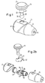
- Fig. 1 shows a block lock with a lock body 11 and one thereof loosened block 13.
- the lock body 11 has a lock body housing 14 made of metal at the top of a frustoconical section has a key opening 15 and an adjoining one cylindrical portion partially from a protective cap 17 Plastic is surrounded.
- On the outer surface of the cylindrical section of the lock body housing 14 and the protective cap 17 have one Insertion opening 19.
- the block 13 has a round locking disk 21 and an adjoining one cylindrical block neck 23 on a substantially spherical locking extension 25 opens.
- the Klobenhals 23 on the part of the locking disk 21 has a wrap-around section 27 and on the part of the locking extension 25 relative to the encompassing section 27 tapered locking section 29.
- the block 13 is in one piece made of metal.
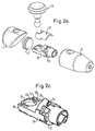
- FIG. 1 shows exploded views of parts of the block lock according to FIG. 1.
- a substantially hollow cylindrical cylinder housing 31 made of metal and an inner housing 33 attached to it Plastic provided, which is essentially the shape of a cylinder segment has.
- a Drive plate 35 made of metal.
- the lock body housing 14 contains a slide bolt 37 made of metal.
- This has a locking section 39 which is in contact and sliding along the inner housing 33 is provided and which is essentially cylindrical segment-shaped with a longitudinal recess is formed so that the locking portion 39 is U-shaped in plan view appears.
- a deflection section 41 On the closed side of the U-shape of the locking section 39 is followed by a deflection section 41, which is essentially has the shape of a hollow cylinder segment and to bear is provided on the drive plate 35.
- a housing cover is within the lock body housing 14 43 and - not shown in FIGS. 2a to 4b - an inside the cylinder housing 31 arranged lock cylinder, one between the lock cylinder and the key opening 15 of the lock body housing 14 arranged Drill protection disc and a detent spring are provided.
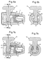
- 5b and 5c, 6a and 6b and 7a and 7b show the structure of the block lock when block 13 is released, when block 13 is inserted or at locked block 13.
- the cylinder housing 31 or the inserted therein Lock cylinders, not shown in the figures, are from the in Fig. 5b held with the reference numeral 45 detent spring.
- the drive plate 35 is between the cylinder housing 31, the inner housing 33 and the slide bolt 37 mounted so that they around the longitudinal axis of the lock body 11 can be rotated. she owns a central coupling recess 47 with which the locking cylinder is engaged to transmit a rotational movement.
- the insertion direction 49 has the inner housing 33 essentially hemispherical receiving recess 51, which together with between the insertion opening 19 and the receiving recess 51 Interior of the lock body housing 14 has a receiving area 53 forms (Fig. 5b).
- the receiving recess 51 opens out with respect to the illustration in FIG. 5b their top on a retaining edge 55 which is perpendicular within a plane runs to the insertion direction 49.
- each other opposing locking cams 57 which are in the receiving recess 51st protrude (Fig. 5c). Behind each of the two locking cams 57 is in the Inner housing 33 a spring back slot 59 is provided (Fig. 2c).
- the housing cover 43 adjoining the inner housing 33 is by means of a locking ring 61 on an inner peripheral surface of the lock body housing 14 secured.
- the protective cap 17 Adjacent to this, has one stabilizing wing star 63 and a protective cap cover 65.
- the protective cap 17, the wing star 63 and the protective cap cover 65 are not shown in FIGS. 7a and 7b.
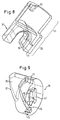
- Fig. 8 shows the sliding bolt 37 obliquely from below, not visible Edges are shown in dashed lines. Some edges of the U-shaped locking section 39 of the slide latch 37 are chamfered for insertion of the block 13 in the receiving area 53 of the lock body 11 allow (see. Fig. 5b and 5c) or a positive grip the locking section 29 of the block neck 23 and the locking extension 25 of the block 13 to ensure (see. Fig. 7a and 7b).
- a guide cam 67 is formed on the inner peripheral surface of the deflection portion 41 of the slide bolt 37. Between the locking section 39 and the deflection section 41 extends curved step edge 69 on the underside shown in FIG. 8 of the slide bolt 37 opens at an engagement slot 71.
- Fig. 9 shows in perspective the side facing the shooting cylinder Driving plate 35.
- an unlocking tongue 73 is formed in the direction of the locking cylinder, which has the shape of a curved triangular surface and a curved one Unlocking end face 75 which extends up to an engagement recess 77 extends on the outer surface of the drive plate 35 (see also Fig. 2b, 3b and 10b).
- the driving plate 35 has a locking tongue in the direction of the sliding bolt 37 79, which has the shape of a curved trapezoidal surface and which is curved to the edge of the lateral surface of the Driver disk 35 has locking end surface 81 (see also Fig. 2b, 7a and 10b).
- the block lock shown in the figures is used to shut off an object by inserting the block 13 into a passage opening of the object and by subsequently locking the block 13 to the Lock body 11.
- the slide bolt 37 is off retracted the receiving area 53 of the lock body 11 to a Inserting the block 13 through the insertion opening 19 into the lock body 11 or a removal of the block 13 from the lock body 11 enable (see. Fig. 5a to 5c).
- This unlocked state of the door lock corresponds to a position of the drive plate 35, in which the locking tongue 79 of the drive plate 35 the engagement slot 71 of the slide bolt 37 penetrates and in which the locking end face 81 faces the step edge 69. Also located the guide cam 67 of the slide bolt 37 at the tip of the unlocking tongue 73 of the drive plate 35.
- This unlocked position of the Driving plate 35 is in particular from FIG. 10a and from FIG. 2a, 2c, 3a, 4a, 5b and 6a can be seen.
- the axial movement of the slide bolt 37 is therefore on the one hand Sliding along the curved locking face 81 along the correspondingly curved step edge 69, and secondly due to that the sliding bolt 37 with its underside on the Top of the inner housing 33 and the cylinder housing 31 abuts (see. Fig. 4a and 4b) and with its top on the inner peripheral surface of the lock body housing 14 rests (cf. FIGS. 6a and 6b and FIG. 7a and 7b).
- the slide latch 37 can not move sideways to the Follow rotational movement of the drive plate 35.
- the sliding bolt 37 guides the axial movement explained through which he eventually tapered the locking portion 29 of the block neck 23 engages from three sides. After graduation this locking movement has the locking tongue 79 of the Driving disk 35 the engagement slot 71 of the slide bolt 37 (Fig. 8) left, and the guide cam 67 is in the engagement recess 77 on the outer surface of the drive plate 35 come to rest. In the the locked position of the block lock reached position the drive plate 35 is in particular from FIG. 10b and from FIG. 2b, 3b, 4b and 7a can be seen.
- the slide latch 37 for locking and unlocking in the axial direction is moved, is only a side access to the slide latch 37 the recording area 53 is required so that the surroundings of the recording area 53 on all other sides regardless of the locking mechanism can be carried out in a shallow depth.
- the recess 51 does not require additional space for the locking mechanism, like this with a rotating locking sleeve is the case according to the prior art.
- Embodiment - a further reduction in the overall depth achieved be that the slide bar 37 flat or at most in the form of a hollow cylinder segment arched with a smaller depth in the direction of insertion 49 as the locking section 39 of the sliding bolt shown 37 is executed, and that the block 13 is shortened accordingly.
- the holding edge 55 which the receiving recess 51 of the inner housing 33 limited with closed circumference, in a relaxed state not a circular course, but instead shows the two to each other opposing locking cams 57 (see. Fig. 2c and Fig. 5b and 5c).
- the inner circumference of the holding edge corresponds to the maximum outer diameter of the locking extension 25 within a plane that is perpendicular to the insertion direction 49, or exceeds this outer diameter only marginally.
- the user can unlock the block 13 remove the lock body 11 safely and in a controlled manner. Vice versa the user can lock the extension 25 in the receiving recess Insert 51 before he then locks the block lock.
Abstract
Description
Die Erfindung betrifft ein Klobenschloß, insbesondere ein Bremsscheibenschloß für Motorräder, mit einem Schloßkörper und einem hieran verriegelbaren Kloben, wobei der Kloben einen Sperranker, einen Verriegelungsfortsatz sowie einen dazwischen angeordneten Klobenhals aufweist, und wobei der Schloßkörper einen Aufnahmebereich zur Aufnahme des Verriegelungsfortsatzes des Klobens, einen Schließzylinder und einen durch eine Drehbetätigung des Schließzylinders bewegbaren Riegel zum Verriegeln oder Entriegeln des in den Aufnahmebereich eingeführten Verriegelungsfortsatzes aufweist.The invention relates to a block lock, in particular a brake disc lock for motorcycles, with a lock body and a lockable to it Block, the block a locking anchor, a locking extension and has a block neck arranged between them, and wherein the lock body has a receiving area for receiving the Locking extension of the block, a lock cylinder and one by rotating the lock cylinder movable bolt for Locking or unlocking the locking extension inserted into the receiving area having.
Um mit Hilfe eines derartigen Klobenschlosses einen Gegenstand abzusperren, wird der Kloben mit seinem Verriegelungsfortsatz voraus durch eine Durchlaßöffnung des Gegenstandes, beispielsweise durch eine Lüftungsöffnung einer Motorradbremsscheibe, geführt, so daß der Sperranker an einem Ende der Durchlaßöffnung anliegt und die Durchlaßöffnung den Klobenhals umgreift. Danach wird der Schloßkörper derart auf den aus dem anderen Ende der Durchlaßöffnung herausstehenden Verriegelungsfortsatz aufgesetzt, daß dieser in den Aufnahmebereich des Schloßkörpers hineinragt. Anschließend wird durch eine Drehbetätigung des Schließzylinders der Riegel über den Verriegelungsfortsatz geführt. Aufgrund des Anliegens des Sperrankers und des verriegelten Schloßkörpers jeweils an einem Ende der Durchlaßöffnung ist das Klobenschloß gegen eine Entnahme aus der Durchlaßöffnung gesichert.To lock an object with the help of such a lock, is the block with its locking extension ahead a passage opening of the object, for example through a ventilation opening a motorcycle brake disc, guided so that the locking anchor abuts at one end of the passage opening and the passage opening Clasped around the neck. Then the lock body is made in such a way the other end of the passage protruding locking extension placed that this in the receiving area of the lock body protrudes. Then by turning the lock cylinder the bolt passed over the locking extension. Because of the Bearing of the locking anchor and the locked lock body in each case One end of the passage opening is the block lock against removal secured from the passage opening.
Für die Verriegelung des Verriegelungsfortsatzes innerhalb des Schloßkörpers ist es bekannt, als Riegel eine durch den Schließzylinder drehbetätigbare Verriegelungshülse mit einer Umfangsnut vorzusehen. Im entriegelten Zustand des Klobenschlosses kann der Verriegelungsfortsatz des Klobens durch einen entsprechend breiten Abschnitt der Umfangsnut hindurch in den Aufnahmebereich des Schloßkörpers eingeführt oder aus diesem herausgeführt werden. Zur Verriegelung des Klobenschlosses wird die Verriegelungshülse gedreht, wobei ein schmälerer Abschnitt der Umfangsnut an dem Klobenhals entlang über den Verriegelungsfortsatz des Klobens gedreht wird, so daß der Verriegelungsfortsatz gegen eine Entnahme aus dem Schloßkörper gesperrt ist.For locking the locking extension inside the lock body it is known as a bolt which can be rotated by the lock cylinder To provide locking sleeve with a circumferential groove. In the unlocked The locking extension of the Klobens through a correspondingly wide section of the circumferential groove inserted through or into the receiving area of the lock body this can be led out. To lock the block lock the locking sleeve rotated with a narrower portion of the circumferential groove along the block neck over the locking extension of the Klobens is rotated so that the locking extension against removal is locked out of the lock body.
Nachteilig an dem bekannten Klobenschloß ist, daß die Unterbringung der um den Aufnahmebereich rotierenden Verriegelungshülse in der Umgebung des Aufnahmebereichs zusätzlichen Raum beansprucht. Dadurch vergrößert sich die Bauform des Klobenschlosses in der Umgebung des Aufnahmebereichs in unerwünschter Weise.A disadvantage of the known block lock is that the accommodation of the surrounding locking sleeve rotating around the receiving area of the recording area takes up additional space. Thereby the design of the block lock increases in the vicinity of the Recording area in an undesirable manner.
Es ist eine Aufgabe der Erfindung, ein Klobenschloß zu schaffen, dessen Verriegelungsmechanismus insbesondere in der Umgebung des für den Verriegelungsfortsatz des Klobens vorgesehenen Aufnahmebereichs ein möglichst geringes Volumen beansprucht.It is an object of the invention to provide a block lock whose Locking mechanism especially in the vicinity of the for Locking extension of the block provided receiving area as small a volume as possible.
Diese Aufgabe wird für ein Klobenschloß der eingangs genannten Art dadurch gelöst, daß der Schloßkörper ferner wenigstens ein Umwandlungselement aufweist, durch das eine Drehbetätigung des Schließzylinders in eine axiale Verriegelungs- oder Entriegelungsbewegung des Riegels umwandelbar ist. This task is thereby for a block lock of the type mentioned solved that the lock body further at least one conversion element has by which a rotary actuation of the lock cylinder in an axial locking or unlocking movement of the bolt can be converted is.
Bei dem erfindungsgemäßen Klobenschloß sorgt also ein Umwandlungselement dafür, daß eine Drehbewegung des Schließzylinders letztlich eine axiale Bewegung des Riegels bewirkt. Daher wird bei einer Entriegelungsbewegung der Riegel dem Aufnahmebereich in einer seitlichen Richtung geradlinig und somit auf einem möglichst direkten Weg entnommen, so daß in der gesamten weiteren Umgebung des Aufnahmebereichs kein Freiraum für eine Verriegelungs- oder Entriegelungsbewegung des Riegels oder für eine entsprechende Verriegelungsmechanik freigehalten werden muß. Insbesondere kann auf einen den Aufnahmebereich umgebenden zylindrischen Freiraum, wie für die Verriegelungshülse gemäß dem Stand der Technik erforderlich, verzichtet werden. Somit führt die durch das Umwandlungselement bewirkte Axialbewegung des Riegels zu einer erheblichen Reduzierung des Platzbedarfs der Verriegelungsmechanik in der Umgebung des Aufnahmebereichs des Schloßkörpers.In the block lock according to the invention, a conversion element is thus provided for the fact that a rotary movement of the locking cylinder ultimately results in a axial movement of the bolt causes. Therefore, an unlocking movement the latch the receiving area in a lateral direction straight and thus taken in the most direct way possible, see above that there is no free space in the entire wider area of the recording area for a locking or unlocking movement of the bolt or be kept free for a corresponding locking mechanism got to. In particular, one can surround the recording area cylindrical clearance, as for the locking sleeve according to the state the technology required. So it leads through Conversion element caused axial movement of the bolt to a considerable extent Reduction of the space requirement of the locking mechanism in the Environment of the receiving area of the lock body.
Da aufgrund der Wirkung des Umfwandlungselements der Riegel lediglich eine axiale Bewegung vollziehen muß, kann er zumindest in der Umgebung des Aufnahmebereichs des Schloßkörpers flach oder lediglich leicht gewölbt ausgebildet sein, wodurch eine weitere vorteilhafte Reduzierung der Schloßkörpertiefe erzielt wird.Because of the effect of the conversion element, the bolt only must perform an axial movement, at least in the area the receiving area of the lock body flat or only slightly be arched, resulting in a further advantageous reduction the lock body depth is achieved.
Ferner ermöglicht die Erfindung eine neue Formgebung des Verriegelungsfortsatzes des Klobens. Bislang war der Verriegelungsfortsatz kugelförmig, also mit einem der Rotationsbewegung der Verriegelungshülse entsprechenden runden Querschnitt ausgestaltet. Da bei der Erfindung lediglich eine axiale Verriegelungs- bzw. Entriegelungsbewegung des Riegels vorgesehen ist, genügt es, wenn der Verriegelungsfortsatz sich scheibenförmig flach mit einem runden oder eckigen Umriß innerhalb einer Ebene erstreckt, die senkrecht zu der Richtung des Einführens des Verriegelungsfortsatzes in den Schloßkörper bzw. zu der Längsrichtung des Klobenhalses verläuft. Eine derartige scheibenförmige Ausgestaltung des Verriegelungsfortsatzes führt zu einer weiteren Reduzierung der Schloßkörpertiefe bzw. des für den Aufnahmebereich benötigten Volumens.Furthermore, the invention enables a new shape of the locking extension of the chop. So far the locking process was spherical, So with one corresponding to the rotational movement of the locking sleeve round cross section. Because in the invention only an axial locking or unlocking movement of the bolt is provided, it is sufficient if the locking extension is disc-shaped flat with a round or angular outline within a level extends perpendicular to the direction of insertion of the locking extension in the lock body or to the longitudinal direction of the block neck runs. Such a disc-shaped configuration of the locking extension leads to a further reduction in the lock body depth or the volume required for the recording area.
Das genannte Umwandlungselement kann als ein separates Bauteil oder an einem separaten Bauteil vorgesehen sein, das sowohl mit dem Schließzylinder als auch mit dem Riegel in Verbindung steht. Alternativ oder zusätzlich kann ein Umwandlungselement in den Riegel und/oder den Schließzylinder integriert sein.Said conversion element can be used as a separate component or be provided on a separate component, both with the lock cylinder as well as with the bolt. Alternatively or additionally can be a conversion element in the bar and / or Lock cylinder can be integrated.
In einer bevorzugten Ausführungsform der Erfindung ist ein innerhalb des Schloßkörpers vorgesehenes Umwandlungselement als eine Schrägführung ausgebildet, die mit einem weiteren Umwandlungselement, insbesondere einem Nocken oder einer weiteren Schrägführung, zusammenwirkt. Diese Schrägführung bzw. die weitere Schrägführung kann beispielsweise als eine gekrümmte Kante eines Teils des Schloßkörpers, als eine Stirnseite eines gekrümmt verlaufenden Abschnitts eines Schloßkörperteils oder als eine innerhalb des Schloßkörpers gekrümmt verlaufende Nut gebildet sein, die jeweils an dem Nocken bzw. der weiteren Schrägführung anliegt oder mit dem Nocken bzw. der weiteren Schrägführung in Eingriff steht.In a preferred embodiment of the invention is within the Lock body provided conversion element as an oblique guide formed with a further conversion element, in particular a cam or another inclined guide. This oblique guidance or the further oblique guidance can, for example as a curved edge of part of the lock body, as an end face of a curved section of a lock body part or as a curved inside the lock body Be formed groove, each on the cam or the further inclined guide abuts or with the cam or the further inclined guide in Intervention stands.
Außerdem ist es möglich, daß zwei Paare jeweils aus Schrägführung und hiermit zusammenwirkendem Nocken bzw. hiermit zusammenwirkender weiteren Schrägführung vorgesehen sind, wobei bei entsprechender Drehbetätigung des Schließzylinders ein Paar die Verriegelungsbewegung des Riegels veranlaßt und das andere Paar die Entriegelungsbewegung. Alternativ hierzu kann auch ein einziges Paar zusammenwirkender Umwandlungselemente vorgesehen sein, beispielsweise für die Entriegelungsbewegung des Riegels. In diesem Fall kann die jeweils entgegengesetzte Axialbewegung des Riegels durch eine Rückstellfeder bewirkt werden.In addition, it is possible that two pairs of inclined guide and hereby interacting cam or hereby interacting further inclined guidance are provided, with appropriate rotation of the lock cylinder a pair the locking movement of the Riegelels causes and the other couple the unlocking movement. alternative this can also be done by a single pair of interacting conversion elements be provided, for example for the unlocking movement of the bar. In this case, the opposite axial movement of the bolt can be effected by a return spring.
Es ist weiterhin bevorzugt, wenn in dem Schloßkörper ein Mitnehmerelement vorgesehen ist, das mit dem Schließzylinder drehwirksam verbunden ist und ein oder mehrere Umwandlungselemente aufweist. Dadurch müssen an dem Schließzylinder selbst keine besonderen Umwandlungselemente vorgesehen sein, was in vorteilhafter Weise den Einsatz handelsüblicher Schließzylinder ermöglicht. Ein derartiges Mitnehmerelement ist allerdings nicht unbedingt erforderlich; beispielsweise kann auch der Nokken des Schließzylinders mit einem an dem Riegel vorgesehenen Umwandlungselement, beispielsweise einer Schrägführung, zusammenwirken.It is further preferred if a driver element is in the lock body is provided, which is rotatably connected to the lock cylinder and has one or more conversion elements. Because of that no special conversion elements on the locking cylinder itself be provided, which is advantageous in the use of commercially available Lock cylinder enables. Such a driver element is, however not necessarily required; for example, the cam the locking cylinder with a conversion element provided on the bolt, for example, an inclined guide.
In einer besonders vorteilhaften Ausführungform der Erfindung ist in der Umgebung des Aufnahmebereichs wenigstens ein Halteelement zum Halten des in den Aufnahmebereich eingeführten Verriegelungsfortsatzes des Klobens vorgesehen. Ein derartiges Halteelement verhindert beim Entriegeln des in den Aufnahmebereich eingeführten Verriegelungsfortsatzes, daß der Kloben unbeabsichtigt den Aufnahmebereich verläßt und aus dem Schloßkörper herausfällt.In a particularly advantageous embodiment of the invention is in the At least one holding element for holding in the vicinity of the receiving area of the locking extension of the inserted into the receiving area Klobens provided. Such a holding element prevents when unlocking the locking extension inserted into the receiving area, that the block unintentionally leaves the receiving area and out of the Lock body falls out.
Ein solches unkontrolliertes Loslösen des Klobens vom Schloßkörper kann zu einer Beschädigung des abgeschlossenen Gegenstandes führen, beispielsweise zu einer Beschädigung einer eine Bremsscheibe umgebenden Motorradfelge. Oft kann ein derartiges unkontrolliertes Loslösen des Klobens jedoch nicht leicht vermieden werden, da beim Aufsperren des Klobenschlosses mit einer Hand der Schließzylinder drehbetätigt und mit der anderen Hand der Schloßkörper gegengehalten wird. Dieses Problem wird durch das Halteelement beseitigt, das den bereits entriegelten Kloben erst freigibt, wenn der Benutzer den entriegelten Kloben bewußt aus dem Schloßkörper herauszieht oder den Schloßkörper vom Kloben abzieht.Such an uncontrolled detachment of the bolt from the lock body can lead to damage to the locked object, for example damage to one surrounding a brake disc Motorcycle rim. Such uncontrolled loosening of the block can often occur but not easily avoided, as when opening the door lock with one hand the lock cylinder rotated and with the the lock body is held against the other hand. This problem will eliminated by the holding element that the already unlocked block releases when the user deliberately releases the unlocked block Pulls the lock body out or pulls the lock body off the block.
Ein solches Halteelement kann bei dem Klobenschloß gemäß dem Stand der Technik nicht ohne weiteres vorgesehen werden, da - wie erläutert - die als Riegel dienende Verriegelungshülse den Aufnahmebereich des Schloßkörpers entlang dessen gesamten Umfangs umgibt und somit keinen Raum läßt für ein zusätzliches Halteelement.Such a holding element can be in the block lock according to the state the technology cannot be readily provided since - as explained - the locking sleeve serving as a bolt the receiving area of Surrounds the lock body along its entire circumference and therefore none There is room for an additional holding element.
Das Halteelement weist vorzugsweise wenigstens ein Rastelement auf, an dem der Verriegelungsfortsatz beim Einführen in den Aufnahmebereich verrastet werden kann. Beispielsweise kann dieses Rastelement durch eine geschlossene, ringartige Haltekante gebildet sein oder durch ein oder mehrere Paare jeweils einander gegenüberstehender Rastarme, die den Verriegelungsfortsatz rückfedernd hintergreifen. Um die erläuterte Haltefunktion auch bei vertikal herabhängendem Kloben erfüllen zu können, ist die von dem Halteelement ausgeübte Haltekraft vorzugsweise größer ist als das Gewicht des Klobens.The holding element preferably has at least one latching element which the locking extension when inserting into the receiving area can be locked. For example, this locking element by a closed, ring-like retaining edge may be formed or by an or several pairs of mutually opposing locking arms that the Reach behind the locking extension and spring back. To the explained holding function to be able to meet even with vertically hanging block the holding force exerted by the holding element is preferably greater than the weight of the butt.
Weitere bevorzugte Ausführungsformen sind in den Unteransprüchen genannt. Nachfolgend wird die Erfindung beispielhaft unter Bezugnahme auf die Zeichnungen beschrieben. In diesen zeigen:
- Fig. 1
- eine Perspektivansicht eines erfindungsgemäßen Klobenschlosses mit einem Schloßkörper und einem hiervon gelösten Kloben,
- Fig. 2a und 2b
- eine Explosionsdarstellung des Klobenschlosses mit einem Innengehäuse, einem Zylindergehäuse und einer dazwischen angeordneten Mitnehmerscheibe, wobei die Mitnehmerscheibe einen Entriegelungszustand bzw. Verriegelungszustand einnimmt,
- Fig. 2c
- eine Detailansicht des Innengehäuses, des Zylindergehäuses und der Mitnehmerscheibe gemäß Fig. 2a,
- Fig. 3a und 3b
- Explosionsdarstellungen des Klobenschlosses, wobei die Mitnehmerscheibe und ein hieran angeordneter Schieberiegel relativ zueinander einen entriegelten bzw. verriegelten Zustand einnehmen,
- Fig. 4a und 4b
- Explosionsdarstellungen des Klobenschlosses, wobei der Schieberiegel einen entriegelten bzw. einen verriegelten Zustand einnimmt,
- Fig. 5a bis 5c
- das Klobenschloß gemäß Fig. 1 in einer Draufsicht, in einem Seitenquerschnitt entlang der Ebene Vb-Vb bzw. in einem Seitenquerschnitt entlang der Ebene Vc-Vc,
- Fig. 6a und 6b
- den Schloßkörper mit darin eingesetztem, jedoch nicht verriegeltem Kloben in einem Seitenquerschnitt bzw. in einem weiteren Seitenquerschnitt entlang der Ebene VIb-VIb,
- Fig. 7a und 7b
- das Klobenschloß gemäß Fig. 6a bzw. 6b in verriegeltem Zustand,
- Fig. 8
- eine Perspektivansicht des Schieberiegels von schräg unten,
- Fig. 9
- eine Perspektivansicht der Mitnehmerscheibe von schräg oben/vorne, und
- Fig. 10a und 10b
- eine Seitenansicht der Mitnehmerscheibe und des daran angeordneten Schieberiegels in einem entriegelten bzw. in einem verriegelten Zustand.
- Fig. 1
- 2 shows a perspective view of a block lock according to the invention with a lock body and a block detached therefrom,
- 2a and 2b
- 2 shows an exploded view of the block lock with an inner housing, a cylinder housing and a drive plate arranged in between, the drive plate assuming an unlocked state or locked state,
- Fig. 2c
- 2 shows a detailed view of the inner housing, the cylinder housing and the drive plate according to FIG. 2a,
- 3a and 3b
- Exploded views of the block lock, wherein the driving plate and a sliding bolt arranged thereon assume an unlocked or locked state relative to one another,
- 4a and 4b
- Exploded views of the block lock, the sliding bolt assuming an unlocked or a locked state,
- 5a to 5c
- 1 in a top view, in a side cross section along the plane Vb-Vb or in a side cross section along the plane Vc-Vc,
- 6a and 6b
- the lock body with inserted but not locked block in a side cross-section or in a further side cross-section along the plane VIb-VIb,
- 7a and 7b
- 6b or 6b in the locked state,
- Fig. 8
- a perspective view of the sliding bolt from obliquely below,
- Fig. 9
- a perspective view of the drive plate obliquely from above / in front, and
- 10a and 10b
- a side view of the drive plate and the sliding bolt arranged thereon in an unlocked or in a locked state.
Fig. 1 zeigt ein Klobenschloß mit einem Schloßkörper 11 und einem hiervon
gelösten Kloben 13. Der Schloßkörper 11 besitzt ein Schloßkörpergehäuse
14 aus Metall, das an der Spitze eines kegelstumpfförmigen Abschnitts
eine Schlüsselöffnung 15 besitzt und an einem hieran anschließenden
zylindrischen Abschnitt teilweise von einer Schutzkappe 17 aus
Kunststoff umgeben ist. An der Mantelfläche des zylindrischen Abschnitts
des Schloßkörpergehäuses 14 besitzen dieses und die Schutzkappe 17 eine
Einführöffnung 19.Fig. 1 shows a block lock with a
Der Kloben 13 weist eine runde Sperrscheibe 21 und einen daran anschließenden
zylindrischen Klobenhals 23 auf, der an einem im wesentlichen
kugelförmigen Verriegelungsfortsatz 25 mündet. Der Klobenhals 23
besitzt seitens der Sperrscheibe 21 einen Umgreifungsabschnitt 27 und
seitens des Verriegelungsfortsatzes 25 einen relativ zu dem Umgreifungsabschnitt
27 verjüngten Verriegelungsabschnitt 29. Der Kloben 13 ist einstückig
aus Metall gefertigt.The
Fig. 2a und 2b, 3a und 3b sowie 4a und 4b zeigen Explosionsdarstellungen
von Teilen des Klobenschlosses gemäß Fig. 1. Innerhalb des Schloßkörpergehäuses
14 sind ein im wesentlichen hohlzylindrisches Zylindergehäuse
31 aus Metall und ein hieran aufgestecktes Innengehäuse 33 aus
Kunststoff vorgesehen, das im wesentlichen die Form eines Zylindersegments
besitzt. Zwischen Zylindergehäuse 31 und Innengehäuse 33 ist eine
Mitnehmerscheibe 35 aus Metall vorgesehen.2a and 2b, 3a and 3b and 4a and 4b show exploded views
of parts of the block lock according to FIG. 1. Within the
Außerdem enthält das Schloßkörpergehäuse 14 einen Schieberiegel 37
aus Metall. Dieser besitzt einen Verriegelungsabschnitt 39, der zum Anliegen
und Verschieben entlang des Innengehäuses 33 vorgesehen ist und
der im wesentlichen zylindersegmentförmig mit einer Längsaussparung
ausgebildet ist, so daß der Verriegelungsabschnitt 39 in Draufsicht U-förmig
erscheint. An die geschlossene Seite der U-Form des Verriegelungsabschnitts
39 schließt sich ein Umlenkungsabschnitt 41 an, der im wesentlichen
die Form eines Hohlzylindersegments besitzt und zum Anliegen
an der Mitnehmerscheibe 35 vorgesehen ist.In addition, the
Ferner sind innerhalb des Schloßkörpergehäuses 14 ein Gehäusedeckel
43 sowie - in den Fig. 2a bis 4b nicht gezeigt - ein innerhalb des Zylindergehäuses
31 angeordneter Schließzylinder, eine zwischen dem Schließzylinder
und der Schlüsselöffnung 15 des Schloßkörpergehäuses 14 angeordnete
Bohrschutzscheibe und eine Rastfeder vorgesehen. Furthermore, a housing cover is within the
Fig. 5b und 5c, 6a und 6b sowie 7a und 7b zeigen den Aufbau des Klobenschlosses
bei gelöstem Kloben 13, bei eingesetztem Kloben 13 bzw. bei
verriegeltem Kloben 13. Das Zylindergehäuse 31 bzw. der darin eingesetzte,
in den Figuren nicht gezeigte Schließzylinder werden von der in Fig.
5b mit dem Bezugszeichen 45 gekennzeichneten Rastfeder gehalten.5b and 5c, 6a and 6b and 7a and 7b show the structure of the block lock
when
Die Mitnehmerscheibe 35 ist zwischen dem Zylindergehäuse 31, dem Innengehäuse
33 und dem Schieberiegel 37 dergestalt gelagert, daß sie um
die Längsachse Schloßkörpers 11 drehbewegt werden kann. Sie besitzt
eine zentrale Kopplungsaussparung 47, mit welcher der Schließzylinder
zur Übertragung einer Drehbewegung in Eingriff steht.The
In Verlängerung der Einführöffnung 19 des Schloßkörpergehäuses 14
hinsichtlich einer senkrecht zur Längsachse des Schloßkörpers 11 verlaufenden
Einführrichtung 49 besitzt das Innengehäuse 33 eine im wesentlichen
halbkugelförmige Aufnahmevertiefung 51, die gemeinsam mit
dem zwischen der Einführöffnung 19 und der Aufnahmevertiefung 51 liegenden
Innenraum des Schloßkörpergehäuses 14 einen Aufnahmebereich
53 bildet (Fig. 5b).In extension of the
Die Aufnahmevertiefung 51 mündet bezüglich der Darstellung Fig. 5b an
ihrer Oberseite an einer Haltekante 55, die innerhalb einer Ebene senkrecht
zu der Einführrichtung 49 verläuft. Diese besitzt abweichend von
einer kreisrunden Form zwei an dem Innengehäuse 33 angeformte, einander
gegenüberstehende Rastnocken 57, die in die Aufnahmevertiefung 51
hineinragen (Fig. 5c). Hinter jedem der beiden Rastnocken 57 ist in dem
Innengehäuse 33 ein Rückfederschlitz 59 vorgesehen (Fig. 2c). The receiving
Der an das Innengehäuse 33 angrenzende Gehäusedeckel 43 ist mittels
eines Sicherungsrings 61 an einer Innenumfangsfläche des Schloßkörpergehäuses
14 gesichert. Hieran angrenzend besitzt die Schutzkappe 17 einen
stabilisierenden Flügelstern 63 sowie einen Schutzkappendeckel 65.
Die Schutzkappe 17, der Flügelstern 63 und der Schutzkappendeckel 65
sind in den Fig. 7a und 7b nicht gezeigt.The
Fig. 8 zeigt den Schieberiegel 37 von schräg unten, wobei nicht sichtbare
Kanten gestrichelt dargestellt sind. Einige Kanten des U-förmigen Verriegelungsabschnitts
39 des Schieberiegels 37 sind angefast, um ein Einführen
des Klobens 13 in den Aufnahmebereich 53 des Schloßkörpers 11 zu
ermöglichen (vgl. Fig. 5b und 5c) bzw. um ein formschlüssiges Umgreifen
des Verriegelungsabschnittes 29 des Klobenhalses 23 sowie des Verriegelungsfortsatzes
25 des Klobens 13 zu gewährleisten (vgl. Fig. 7a und 7b).Fig. 8 shows the sliding
An der Innenumfangsfläche des Umlenkungsabschnitts 41 des Schieberiegels
37 ist ein Führungsnocken 67 angeformt. Zwischen dem Verriegelungsabschnitt
39 und dem Umlenkungsabschnitt 41 erstreckt sich eine
gekrümmt verlaufende Stufenkante 69, die an der in Fig. 8 gezeigten Unterseite
des Schieberiegels 37 an einem Eingriffsschlitz 71 mündet.On the inner peripheral surface of the deflection portion 41 of the
Fig. 9 zeigt perspektivisch die dem Schießzylinder zugewandte Seite der
Mitnehmerscheibe 35. An deren Außenumfang ist in axialer Verlängerung
in Richtung des Schließzylinders eine Entriegelungszunge 73 angeformt,
welche die Form einer gekrümmten Dreiecksfläche besitzt und eine gekrümmte
Entriegelungsstirnfläche 75 aufweist, die sich bis zu einer Eingriffsvertiefung
77 an der Mantelfläche der Mitnehmerscheibe 35 erstreckt
(vgl. auch Fig. 2b, 3b und 10b).Fig. 9 shows in perspective the side facing the shooting
In axialer Verlängerung des Außenumfangs der Mitnehmerscheibe 35 in
Richtung des Schieberiegels 37 besitzt die Mitnehmerscheibe 35 eine Verriegelungszunge
79, welche die Form einer gekrümmten Trapezfläche besitzt
und welche eine gekrümmt bis an den Rand der Mantelfläche der
Mitnehmerscheibe 35 verlaufende Verriegelungsstirnfläche 81 aufweist
(vgl. auch Fig. 2b, 7a und 10b).In an axial extension of the outer circumference of the
Das in den Fig. gezeigte Klobenschloß dient zum Absperren eines Gegenstandes
durch Einführen des Klobens 13 in eine Durchlaßöffnung des Gegenstandes
und durch anschließendes Verriegeln des Klobens 13 an dem
Schloßkörper 11. Dadurch ist der Umgreifungsabschnitt 27 des Klobenhalses
23 radial von der Durchlaßöffnung und axial von der Sperrscheibe
21 bzw. von dem Schloßkörper 11 gefangen. Erfindungsgemäß wird bei
dem Verriegeln eine Drehbetätigung des Schließzylinders bzw. der hiermit
verbundenen Mitnehmerscheibe 35 in eine axiale Verriegelungs- bzw. Entriegelungsbewegung
des Schieberiegels 37 umgewandelt. Diese Umwandlung
wird nachfolgend näher erläutert.The block lock shown in the figures is used to shut off an object
by inserting the
Im entriegelten Zustand des Klobenschlosses ist der Schieberiegel 37 aus
dem Aufnahmebereich 53 des Schloßkörpers 11 zurückgezogen, um ein
Einführen des Klobens 13 durch die Einführöffnung 19 in den Schloßkörper
11 oder eine Entnahme des Klobens 13 aus dem Schloßkörper 11 zu
ermöglichen (vgl. Fig. 5a bis 5c). Dieser entriegelte Zustand des Klobenschlosses
entspricht einer Stellung der Mitnehmerscheibe 35, in welcher
die Verriegelungszunge 79 der Mitnehmerscheibe 35 den Eingriffsschlitz
71 des Schieberiegels 37 durchdringt und in welcher die Verriegelungsstirnfläche
81 der Stufenkante 69 gegenübersteht. Außerdem befindet sich
der Führungsnocken 67 des Schieberiegels 37 an der Spitze der Entriegelungszunge
73 der Mitnehmerscheibe 35. Diese entriegelte Stellung der
Mitnehmerscheibe 35 ist insbesondere aus Fig. 10a sowie aus den Fig. 2a,
2c, 3a, 4a, 5b und 6a ersichtlich.In the unlocked state of the block lock, the
Um ausgehend von diesem entriegelten Zustand den gemäß Fig. 6a und
6b in den Schloßkörper 11 eingeführten Kloben 13 zu verriegeln, wird
mittels eines passenden Schlüssels der Schließzylinder drehbetätigt und
somit die Mitnehmerscheibe 35 bezüglich der Ansicht gemäß Fig. 9 um
90° entgegen dem Uhrzeigersinn gedreht. Dadurch gelangt die Verriegelungsstirnfläche
81 der Verriegelungszunge 79 in flächigem Kontakt mit
der Stufenkante 69, wodurch bei andauernder Drehbewegung der Mitnehmerscheibe
35 der Schieberiegel 37 zu einer axialen Bewegung weg
von der Mitnehmerscheibe 35 gezwungen wird (vgl. 10a).To proceed from this unlocked state according to FIGS. 6a and
6b in the
Die axiale Bewegung des Schieberiegels 37 ist also zum einen auf das
Entlanggleiten der gekrümmten Verriegelungstirnfläche 81 entlang der
entsprechend gekrümmten Stufenkante 69, und zum anderen darauf zurückzuführen,
daß der Schieberiegel 37 mit seiner Unterseite an der
Oberseite des Innengehäuses 33 bzw. des Zylindergehäuses 31 anliegt
(vgl. Fig. 4a und 4b) und mit seiner Oberseite an der Innenumfangsfläche
des Schloßkörpergehäuses 14 anliegt (vgl. Fig. 6a und 6b sowie Fig. 7a
und 7b). Der Schieberiegel 37 kann also nicht seitlich ausweichen, um der
Drehbewegung der Mitnehmerscheibe 35 zu folgen. The axial movement of the
Stattdessen führt der Schieberiegel 37 die erläuterte axiale Bewegung
durch, aufgrund derer er schließlich den verjüngten Verriegelungsabschnitt
29 des Klobenhalses 23 von drei Seiten aus umgreift. Nach Abschluß
dieser Verriegelungsbewegung hat die Verriegelungszunge 79 der
Mitnehmerscheibe 35 den Eingriffsschlitz 71 des Schieberiegels 37 (Fig. 8)
verlassen, und der Führungsnocken 67 ist in der Eingriffsvertiefung 77 an
der Mantelfläche der Mitnehmerscheibe 35 zu liegen gekommen. Die in
dem derartig verriegelten Zustand des Klobenschlosses erreichte Stellung
der Mitnehmerscheibe 35 ist insbesondere aus Fig. 10b sowie aus den Fig.
2b, 3b, 4b und 7a ersichtlich.Instead, the sliding
Um nun ausgehend von diesem verriegelten Zustand des Klobenschlosses
zur erneuten Freigabe des Klobens 13 den Schieberiegel 37 wieder zurückzuziehen,
wird die Mitnehmerscheibe 35 - mittels entsprechender
Drehbetätigung des Zylinderschlosses durch den passenden Schlüssel -
gemäß der Ansicht nach Fig. 9 im Uhrzeigersinn gedreht. Dadurch legt
sich die Entriegelungsstirnfläche 75 der Entriegelungszunge 73 (Fig. 10b)
an den Führungsnocken 67 des Schieberiegels 37 an und führt diesen bei
andauernder Drehbewegung entlang der gesamten Länge der Entriegelungsstirnfläche
75. Dadurch wird der Schieberiegel 37 in axialer Richtung
von dem Verriegelungsabschnitt 29 des Klobenhalses 23 weggezogen,
und die Verriegelungszunge 79 dringt allmählich in den Eingriffsschlitz 71
des Schieberiegels 37 ein. Durch Abschluß einer 90°-Drehung der Mitnehmerscheibe
35 wird auf diese Weise wieder der Entriegelungszustand
des Klobenschlosses erreicht.To now proceed from this locked state of the block lock
to release the
Da der Schieberiegel 37 zum Verriegeln und Entriegeln in axialer Richtung
bewegt wird, ist lediglich ein seitlicher Zugang des Schieberiegels 37 zu
dem Aufnahmebereich 53 erforderlich, so daß die Umgebung des Aufnahmebereichs
53 an allen anderen Seiten ohne Rücksicht auf den Verriegelungsmechnismus
in geringer Bautiefe ausgeführt werden kann. Insbesondere
besteht bezüglich der Darstellung gemäß Fig. 5b und 5c unterhalb
der Aufnahmevertiefung 51 kein zusätzlicher Platzbedarf für den Verriegelungsmechnismus,
wie dies bei einer rotierenden Verriegelungshülse
gemäß dem Stand der Technik der Fall ist.Since the
Im übrigen kann - abweichend von dem in den Figuren dargestellten
Ausführungsbeispiel - eine weitere Reduzierung der Bautiefe dadurch erreicht
werden, daß der Schieberiegel 37 flach oder allenfalls in der Form
eines Hohlzylindersegments gewölbt mit einer geringeren Tiefe in Einführrichtung
49 als der Verriegelungsabschnitt 39 des gezeigten Schieberiegels
37 ausgeführt wird, und daß der Kloben 13 entsprechend verkürzt wird.For the rest - different from that shown in the figures
Embodiment - a further reduction in the overall depth achieved
be that the
Bei dem in den Figuren dargestellten Ausführungsbeispiel wird der durch
die lediglich axiale Bewegung des Schieberiegels 37 erzielte Platzgewinn
dazu ausgenutzt, um eine besonders vorteilhafte Rasthalterung des in den
Schloßkörper 11 eingeführten, jedoch nicht verriegelten Klobens 13 zu
ermöglichen. Diese Rasthalterung wird im folgenden näher erläutert:In the embodiment shown in the figures, the by
the only axial movement of the
Die Haltekante 55, welche die Aufnahmevertiefung 51 des Innengehäuses
33 mit geschlossenem Umfang begrenzt, besitzt in entspanntem Zustand
keinen kreisrunden Verlauf, sondern weist stattdessen die zwei einander
gegenüberstehenden Rastnocken 57 (vgl. Fig. 2c sowie Fig. 5b und 5c).
Der Innenumfang der Haltekante entspricht dem maximalen Außendurchmesser
des Verriegelungsfortsatzes 25 innerhalb einer Ebene, die
senkrecht zu der Einführrichtung 49 steht, oder überschreitet diesen Außendurchmesser
lediglich geringfügig.The holding
Beim Einführen des Verriegelungsfortsatzes 25 in die Aufnahmevertiefung
51 wird die Haltekante 55 aufgrund einer Ausbildung des Innengehäuses
33 aus elastischem Kunststoff sowie aufgrund der Vorsehung der Rückfederschlitze
59 kurzzeitig zu einem dem Außendurchmesser des Verriegelungsfortsatzes
25 entsprechenden Verlauf umgeformt. Nach vollständigem
Einführen des Verriegelungsfortsatzes 25 in die Aufnahmevertiefung
51 federt die Haltekante 55 in ihre normale, nicht kreisrunde Form zurück,
so daß der Verriegelungsfortsatz 25 zumindest von den beiden Rastnocken
57 hintergriffen wird (vgl. Fig. 6b). Dadurch wird der in den
Schloßkörper 11 eingesetzte Kloben 13 gehalten, und zwar auch dann,
wenn der Kloben 13 nicht verriegelt ist.When inserting the locking
Durch Überwindung der von der Haltekante 55 auf den Verriegelungsfortsatz
25 ausgeübten Haltekraft kann der Benutzer den entriegelten Kloben
13 dem Schloßkörper 11 sicher und kontrolliert entnehmen. Umgekehrt
kann der Benutzer den Verriegelungsfortsatz 25 in die Aufnahmevertiefung
51 einstecken, bevor er das Klobenschloß anschließend verriegelt.By overcoming the from the retaining
Zu der aus Fig. 2c ersichtlichen Ausgestaltung der Haltekante 55 ist anzumerken,
daß deren Verlauf nicht unbedingt geschlossen ausgeführt sein
muß, sondern auch unterbrochen sein kann, so daß beispielsweise die
beiden Rastnocken 57 als im wesentliche freistehende Rastarme ausgestaltet
sein können. Alternativ hierzu ist es auch möglich, die Haltekante
55 ohne Rastnocken, jedoch mit einem geschlossenen ovalen Verlauf zu
versehen. Regarding the configuration of the holding
- 1111
- Schloßkörperlock body
- 1313
- KlobenKloben
- 1414
- SchloßkörpergehäuseLock body housing
- 1515
- Schlüsselöffnungkey opening
- 1717
- Schutzkappeprotective cap
- 1919
- Einführöffnunginsertion
- 2121
- Sperrscheibelocking disc
- 2323
- KlobenhalsKlobenhals
- 2525
- VerriegelungsfortsatzLocking extension
- 2727
- UmgreifungsabschnittUmgreifungsabschnitt
- 2929
- Verriegelungsabschnittlocking section
- 3131
- Zylindergehäusecylinder housing
- 3333
- Innengehäuseinner housing
- 3535
- Mitnehmerscheibedriver disc
- 3737
- Schieberiegelslide bolt
- 3939
- Verriegelungsabschnittlocking section
- 4141
- Umlenkungsabschnittdeflection section
- 4343
- Gehäusedeckelhousing cover
- 4545
- Rastfederdetent spring
- 4747
- Kopplungsaussparungcoupling recess
- 4949
- Einführrichtunginsertion
- 5151
- Aufnahmevertiefungreceiving recess
- 5353
- Aufnahmebereichreception area
- 5555
- Haltekanteretaining edge
- 5757
- Rastnockenlocking cams
- 5959
- Rückfederschlitz Rear spring slot
- 6161
- Sicherungsringcirclip
- 6363
- Flügelsternwing star
- 6565
- SchutzkappendeckelCap lid
- 6767
- Führungsnockenguide cam
- 6969
- Stufenkantestep edge
- 7171
- Eingriffsschlitzengagement slot
- 7373
- Entriegelungszungeunlocking tongue
- 7575
- EntriegelungsstirnflächeEntriegelungsstirnfläche
- 7777
- Eingriffsvertiefungengaging recess
- 7979
- Verriegelungszungelocking tab
- 8181
- VerriegelungsstirnflächeLocking face
Claims (12)
wobei der Kloben (13) einen Sperranker (21), einen Verriegelungsfortsatz (25) sowie einen dazwischen angeordneten Klobenhals (23) aufweist, und
wobei der Schloßkörper (11) einen Aufnahmebereich (53) zur Aufnahme des Verriegelungsfortsatzes (25) des Klobens (13), einen Schließzylinder und einen durch eine Drehbetätigung des Schließzylinders bewegbaren Riegel (37) zum Verriegeln oder Entriegeln des in den Aufnahmebereich (53) eingeführten Verriegelungsfortsatzes (25) aufweist;
dadurch gekennzeichnet,
wherein the block (13) has a locking anchor (21), a locking extension (25) and an intermediate block neck (23), and
wherein the lock body (11) has a receiving area (53) for receiving the locking extension (25) of the bolt (13), a locking cylinder and a lock (37) movable by turning the locking cylinder for locking or unlocking the one inserted into the receiving area (53) Has locking extension (25);
characterized,
dadurch gekennzeichnet,
characterized,
dadurch gekennzeichnet,
characterized,
dadurch gekennzeichnet,
characterized,
dadurch gekennzeichnet,
characterized,
dadurch gekennzeichnet,
characterized,
dadurch gekennzeichnet,
characterized,
dadurch gekennzeichnet,
characterized,
dadurch gekennzeichnet,
characterized,
dadurch gekennzeichnet,
characterized,
dadurch gekennzeichnet,
characterized,
dadurch gekennzeichnet,
characterized,
Applications Claiming Priority (2)
| Application Number | Priority Date | Filing Date | Title |
|---|---|---|---|
| DE19938740A DE19938740A1 (en) | 1999-08-16 | 1999-08-16 | A lock |
| DE19938740 | 1999-08-16 |
Publications (2)
| Publication Number | Publication Date |
|---|---|
| EP1077174A2 true EP1077174A2 (en) | 2001-02-21 |
| EP1077174A3 EP1077174A3 (en) | 2002-09-11 |
Family
ID=7918517
Family Applications (1)
| Application Number | Title | Priority Date | Filing Date |
|---|---|---|---|
| EP00116329A Withdrawn EP1077174A3 (en) | 1999-08-16 | 2000-07-27 | Disc brake lock |
Country Status (3)
| Country | Link |
|---|---|
| US (1) | US6457336B1 (en) |
| EP (1) | EP1077174A3 (en) |
| DE (1) | DE19938740A1 (en) |
Families Citing this family (17)
| Publication number | Priority date | Publication date | Assignee | Title |
|---|---|---|---|---|
| US6913413B2 (en) * | 2002-07-24 | 2005-07-05 | Yao-Kun Yang | Coupling lock |
| DE102004052463A1 (en) * | 2004-10-28 | 2006-05-04 | ABUS August Bremicker Söhne KG | Two wheeler lock e.g. frame lock, has body with two turning bolts, which engage at locking bolt in different directions in locking position, and drive dog driving turning bolts opposite to one another for releasing locking bolt |
| US20070022792A1 (en) * | 2005-07-29 | 2007-02-01 | New Hampton Technologies, Llc | Vehicle Lock |
| US20080041127A1 (en) | 2005-07-29 | 2008-02-21 | New Hampton Technologies, Llc | Vehicle Lock |
| US7467530B2 (en) * | 2005-07-29 | 2008-12-23 | New Hampton Technologies Llc | Vehicle lock |
| US7165427B1 (en) * | 2005-09-07 | 2007-01-23 | Yung-Tsai Lai | Lock device for a box |
| US7513133B2 (en) * | 2005-11-04 | 2009-04-07 | Luma Industrias, S.A. | Padlock device for the shaft of two-wheeled vehicles |
| US8016327B2 (en) * | 2006-08-09 | 2011-09-13 | Hartwell Corporation | Bifurcated latching system |
| US8925979B2 (en) | 2006-11-30 | 2015-01-06 | Hartwell Corporation | Command latch and pin latch system |
| US8302435B2 (en) * | 2008-08-25 | 2012-11-06 | Master Lock Company Llc | Pin locking device |
| CN101761270B (en) * | 2008-12-22 | 2013-05-08 | 鸿富锦精密工业(深圳)有限公司 | Locking structure |
| TWI425138B (en) * | 2009-01-16 | 2014-02-01 | Hon Hai Prec Ind Co Ltd | Locking structure |
| US20120055210A1 (en) * | 2010-09-08 | 2012-03-08 | Kenneth Biba | Locking assembly |
| US20120212000A1 (en) * | 2011-02-22 | 2012-08-23 | Handyway Co., Ltd. | Trailer lock |
| DE102015118311A1 (en) | 2015-10-27 | 2017-04-27 | ABUS August Bremicker Söhne KG | safety device |
| USD820662S1 (en) * | 2016-06-20 | 2018-06-19 | ABUS August Bremicker Söhne KG | Fastener for bicycle |
| ES2934588T3 (en) | 2018-04-03 | 2023-02-23 | Knox Ass Inc Dba Knox Company | Protector and fluid absorber for locking devices |
Family Cites Families (11)
| Publication number | Priority date | Publication date | Assignee | Title |
|---|---|---|---|---|
| EP0413065A1 (en) | 1989-08-16 | 1991-02-20 | Malcolm Ian Weaver | Alarm lock |
| DE9210554U1 (en) * | 1992-08-06 | 1992-10-08 | Shieh, Jin-Ren, Taichung, Tw | |
| US5331830A (en) * | 1993-02-03 | 1994-07-26 | Su Mao C | Cylindrical lock |
| NL9401625A (en) * | 1993-10-27 | 1995-05-16 | Diamond Flex B V | Key lock. |
| US5410895A (en) * | 1993-12-22 | 1995-05-02 | Hsu; Chung-Hung | U-shaped lock |
| US5511400A (en) * | 1994-10-07 | 1996-04-30 | Ma; Ding-Chiang | Lock mechanism for use in a securing device |
| US5568740A (en) * | 1995-08-15 | 1996-10-29 | Lin; Yung-Ta | Steel wire rope lock |
| DE29614359U1 (en) * | 1996-08-19 | 1996-10-17 | Kuo Li Tsao | Wheel locking device |
| DE29712509U1 (en) * | 1997-07-15 | 1997-10-30 | Kuo Li Tsao | Piston bolt for brake disc lock |
| US6055833A (en) * | 1998-01-09 | 2000-05-02 | Ding-Chiang; Ma | Plug lock |
| US5964107A (en) * | 1998-04-28 | 1999-10-12 | Chang; Kuo-Chou | Lock |
-
1999
- 1999-08-16 DE DE19938740A patent/DE19938740A1/en not_active Withdrawn
-
2000
- 2000-07-27 EP EP00116329A patent/EP1077174A3/en not_active Withdrawn
- 2000-08-15 US US09/639,013 patent/US6457336B1/en not_active Expired - Fee Related
Non-Patent Citations (1)
| Title |
|---|
| None |
Also Published As
| Publication number | Publication date |
|---|---|
| US6457336B1 (en) | 2002-10-01 |
| EP1077174A3 (en) | 2002-09-11 |
| DE19938740A1 (en) | 2001-02-22 |
Similar Documents
| Publication | Publication Date | Title |
|---|---|---|
| EP1077174A2 (en) | Disc brake lock | |
| EP1153186B1 (en) | Closure for connecting two thin walls | |
| DE60036005T2 (en) | BARS | |
| EP2261447B1 (en) | Padlock | |
| DE102007044088A1 (en) | Binary coded key and tamper proof lock | |
| EP0361155B1 (en) | Support for a long stirrup lock | |
| EP3153648B1 (en) | Padlock | |
| DE102009039156A1 (en) | Loop lock with staggered cylinder axis | |
| EP3741932B1 (en) | Folding lock | |
| DE202005020043U1 (en) | Bolting device for e.g. cabinets has movable pin that allows or prevents torque transfer between rotor and knob when rotor and knob are respectively coupled or uncoupled | |
| EP0555633B1 (en) | Door handle fitting | |
| EP2317037A2 (en) | Swivel lever lock with split actuation shaft | |
| DE69907311T2 (en) | Axially disengaging lock for a locking mechanism of a passenger car | |
| DE4325178A1 (en) | Cylinder lock | |
| DE69916122T2 (en) | CYLINDER LOCK | |
| EP0713946B1 (en) | Furniture lock or locking | |
| DE60009812T2 (en) | Door lock device with removable operating handle | |
| WO2018114400A1 (en) | Padlock | |
| DE2723887B2 (en) | Fixing device for lock cylinder | |
| EP0520154B1 (en) | Cable locking device on a two wheel frame | |
| DE102008014637B4 (en) | cylinder lock | |
| DE1678041B2 (en) | ROTATING CYLINDER LOCK ARRANGEMENT IN AN EXTERNAL KNOB OF A LOCK | |
| DE69426015T3 (en) | Cylinder lock device secured against unauthorized unlocking | |
| DE2530666C2 (en) | Push rotary cylinder lock | |
| EP3974606B1 (en) | Locking device, lock arrangement and motor vehicle |
Legal Events
| Date | Code | Title | Description |
|---|---|---|---|
| PUAI | Public reference made under article 153(3) epc to a published international application that has entered the european phase |
Free format text: ORIGINAL CODE: 0009012 |
|
| AK | Designated contracting states |
Kind code of ref document: A2 Designated state(s): AT BE CH CY DE DK ES FI FR GB GR IE IT LI LU MC NL PT SE |
|
| AX | Request for extension of the european patent |
Free format text: AL;LT;LV;MK;RO;SI |
|
| PUAL | Search report despatched |
Free format text: ORIGINAL CODE: 0009013 |
|
| AK | Designated contracting states |
Kind code of ref document: A3 Designated state(s): AT BE CH CY DE DK ES FI FR GB GR IE IT LI LU MC NL PT SE |
|
| AX | Request for extension of the european patent |
Free format text: AL;LT;LV;MK;RO;SI |
|
| AKX | Designation fees paid | ||
| REG | Reference to a national code |
Ref country code: DE Ref legal event code: 8566 |
|
| STAA | Information on the status of an ep patent application or granted ep patent |
Free format text: STATUS: THE APPLICATION IS DEEMED TO BE WITHDRAWN |
|
| 18D | Application deemed to be withdrawn |
Effective date: 20030312 |