EP1351613B1 - Externer fixateur - Google Patents
Externer fixateur Download PDFInfo
- Publication number
- EP1351613B1 EP1351613B1 EP01995518A EP01995518A EP1351613B1 EP 1351613 B1 EP1351613 B1 EP 1351613B1 EP 01995518 A EP01995518 A EP 01995518A EP 01995518 A EP01995518 A EP 01995518A EP 1351613 B1 EP1351613 B1 EP 1351613B1
- Authority
- EP
- European Patent Office
- Prior art keywords
- bar
- carrier
- screw
- clamp
- cylindrical
- Prior art date
- Legal status (The legal status is an assumption and is not a legal conclusion. Google has not performed a legal analysis and makes no representation as to the accuracy of the status listed.)
- Expired - Lifetime
Links
- 210000000988 bone and bone Anatomy 0.000 claims abstract description 28
- 239000012634 fragment Substances 0.000 claims abstract description 17
- 239000000969 carrier Substances 0.000 claims abstract description 9
- 238000003825 pressing Methods 0.000 claims description 18
- 230000002146 bilateral effect Effects 0.000 claims 1
- 230000000149 penetrating effect Effects 0.000 claims 1
- 238000010276 construction Methods 0.000 abstract description 11
- 230000006835 compression Effects 0.000 abstract description 6
- 238000007906 compression Methods 0.000 abstract description 6
- 238000004519 manufacturing process Methods 0.000 abstract description 4
- 206010017076 Fracture Diseases 0.000 description 7
- 230000009467 reduction Effects 0.000 description 7
- 208000010392 Bone Fractures Diseases 0.000 description 6
- 210000002414 leg Anatomy 0.000 description 5
- 238000000034 method Methods 0.000 description 5
- 208000003044 Closed Fractures Diseases 0.000 description 4
- 206010043183 Teething Diseases 0.000 description 3
- 230000035515 penetration Effects 0.000 description 3
- 238000000926 separation method Methods 0.000 description 3
- 230000036346 tooth eruption Effects 0.000 description 3
- 238000002360 preparation method Methods 0.000 description 2
- 210000002303 tibia Anatomy 0.000 description 2
- 210000000689 upper leg Anatomy 0.000 description 2
- 206010061599 Lower limb fracture Diseases 0.000 description 1
- 208000027418 Wounds and injury Diseases 0.000 description 1
- 235000005505 Ziziphus oenoplia Nutrition 0.000 description 1
- 244000104547 Ziziphus oenoplia Species 0.000 description 1
- 230000009471 action Effects 0.000 description 1
- 238000004140 cleaning Methods 0.000 description 1
- 239000002131 composite material Substances 0.000 description 1
- 230000001419 dependent effect Effects 0.000 description 1
- 230000000694 effects Effects 0.000 description 1
- 230000035876 healing Effects 0.000 description 1
- 238000005304 joining Methods 0.000 description 1
- 210000003127 knee Anatomy 0.000 description 1
- 210000001699 lower leg Anatomy 0.000 description 1
- 239000000463 material Substances 0.000 description 1
- 230000007246 mechanism Effects 0.000 description 1
- 230000002980 postoperative effect Effects 0.000 description 1
- 230000002265 prevention Effects 0.000 description 1
- 230000008569 process Effects 0.000 description 1
Images


Classifications
-
- A—HUMAN NECESSITIES
- A61—MEDICAL OR VETERINARY SCIENCE; HYGIENE
- A61B—DIAGNOSIS; SURGERY; IDENTIFICATION
- A61B17/00—Surgical instruments, devices or methods
- A61B17/56—Surgical instruments or methods for treatment of bones or joints; Devices specially adapted therefor
- A61B17/58—Surgical instruments or methods for treatment of bones or joints; Devices specially adapted therefor for osteosynthesis, e.g. bone plates, screws or setting implements
- A61B17/60—Surgical instruments or methods for treatment of bones or joints; Devices specially adapted therefor for osteosynthesis, e.g. bone plates, screws or setting implements for external osteosynthesis, e.g. distractors, contractors
- A61B17/66—Alignment, compression or distraction mechanisms
-
- A—HUMAN NECESSITIES
- A61—MEDICAL OR VETERINARY SCIENCE; HYGIENE
- A61B—DIAGNOSIS; SURGERY; IDENTIFICATION
- A61B17/00—Surgical instruments, devices or methods
- A61B17/56—Surgical instruments or methods for treatment of bones or joints; Devices specially adapted therefor
- A61B17/58—Surgical instruments or methods for treatment of bones or joints; Devices specially adapted therefor for osteosynthesis, e.g. bone plates, screws or setting implements
- A61B17/60—Surgical instruments or methods for treatment of bones or joints; Devices specially adapted therefor for osteosynthesis, e.g. bone plates, screws or setting implements for external osteosynthesis, e.g. distractors, contractors
- A61B17/64—Devices extending alongside the bones to be positioned
- A61B17/6466—Devices extending alongside the bones to be positioned with pin-clamps movable along a solid connecting rod
Definitions
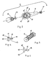
- the invention relates to an external skeletal fixator, which comprises at least two pins (4), that can be placed in each of the main bone fragments.
- One of the most famous external fixator is Hoffmann's. It consists of at least two clamps used for the fixation of the pins screwed into the bone, longitudinal bar and a ball-like joint that establishes the connection between the clamp and the bar.
- the clamp may be used for the fixation of two to five pins. While being screwed into the bone, the pins have to be parallel and at the exactly designated mutual distance that is determined in advance, and that depends on the gutters on the clamps.
- the bar may be divided in two parts so that - by the addition of some special nuts and screws - it may be shortened or made longer. The elements of this system may be combined and thus build the constructions of various complexities.
- the object of the invention is to provide an external, skeletal fixator which renders it possible to use conventional pins without any kind of guidance, whereby the pins will have the three-dimensional freedom of movement, while the whole construction provides a balanced three-dimensional stability during which the apparatus is highly adjustable, suitable for the compression and distraction and manageable for clinical application and production.
- the primary goal of the invention is finding the solution to the problem of the balanced three-dimensional fixation of the fractures, dynamisation, accurate closed fractures reduction, high mobility and independent introduction of any pin. Apart from that, the application and managing of the fixator has to be simple, even for a beginner, as well as easy for the production.
- the essence of the invention lies in the achievement of the free and reliable sliding of the carrier of the clamp in relation to the bar, securing the conditions for the compression and distraction, whereby, there is neither the phenomenon of self-locking nor the looseness among the components.
- This is accomplished by the construction of the carrier of the clamp that is put on the bar over the cylindrical hole, so that the sliding of the carrier of the clamp across the bar is going on smoothly and without self-locking; whereby, there is no excessive looseness between the bar and the carrier of the clamp, disregarding the fact whether the screw, used for the fixation of the carrier of the clamp to the bar, is more or less unscrewed, or is entirely unscrewed and separated from the carrier of the clamp. This enables even the possibility of compression and distraction across the carrier of the clamp.
- the essence lies in the achievement of the three-dimensional freedom of the application of each pin.
- the frame of the fixator may always be placed, regardless of the position of already applied pins through the bone.
- This is made possible by the construction of the clamp, which has rotator and sliding freedom in relation to the pin and to the carrier of the clamp and rotator and sliding freedom of the carrier of the clamp in relation to the bar, whereby, clamp can be fixed to the pin and to the carrier of the clamp and carrier of the clamp can be fixed to the bar.
- the author of both this method and this invention recommends that the pins in the tibia to be applied convergently, mutually closing the angle of 90°. Afterwards, the precise setting of the position of the fragments is carried out by the sliding movement of the carrier of the clamp across the bar. When the desired position of the bone fragment is achieved, all screws and nuts are strongly tightened. Later on, the distraction or compression may be carried out by the special additional device, whether by using the telescopic or ordinary bar.
- the external skeletal fixator has many advantages, among which the most important are the following:
- figure 1 of the enclosed drawing may be viewed by perceiving external skeletal fixator that consists of bar 1, carrier of clamp 2 of clamp 3 and pin 4.
- the extended complex of fixator includes telescopic and plate-like comressively-distractional device 5, 6, shown by figures 16 and 17, and special clamp 7 for simultaneous tightening of two bars 1, shown by figures 18 and 19.
- the bar of external skeletal fixator is circular cross-sectioned bar on which carrier of the clamp 2 is pulled; before fixation, carrier of clamp can be moved in both directions along bar 1, or it can be moved rotationally around bar 1.
- carrier 2 of clamp adjustable clamp 3 is pulled on; it is at same time axially and rotationally movable, both in relation to carrier of clamp 2 and in relation to pin 4, which is screwed into bone.
- carrier 2 of clamp shown by figures from 2 to 9, includes circular bar-like body 8, which, on one of its ends, has coaxially widened cylindrical extension 9, through which circular holes 10 and 10' are vertically pierced.
- the middle axes of bar-like body 8 and circular holes 10, 10' are mutually perpendicular.
- the body 8 is used for carrying of clamps 3, whereas holes 10 and 10' for connection to bar 1.
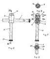
- Thread 11 is made, in which screw 12 is screwed with profile-like pressing element 13 situated inside gutter 14 on screw 12.
- the shape of gutter 14 reminds of keyhole.
- the pressing element 13, separately shown by figures 4, 5 and 7, consists of cylindrical neck 15 that on one of its ends has ball 16, while on other end cylinder 17 with pressing surface 18 which is negative - cylinder shape.
- the ball 16 and larger part of neck 15 are placed inside gutter 14, while negative-cylinder 17, which serves purpose of better fixation of bar I to carrier 2 of clamp, occupies forward position in relation to gutter 14.
- Figure 10 of drawings shows other variation of threaded screw 12A and negative-cylindrical pressing element 13A.
- screw 12A has no profile gutter 14; yet, it has smaller hole 22 pierced beginning from end of trunk, on which a spherical expansion 23 is spherically continued.
- the negative-cylindrical pressing element 3A is altered as long as his ball 16A is vertically cut forming slit 24.
- the connection of both elements is achieved by placing cut ball 16A through narrower hole 22 as well as its placing inside spherical expansion 23, out of which it cannot break loose easily, once it penetrates there.
- the second variation of carrier 2A of clamp (see figure 11) consists of bar-like circular tubular body 25 with inner thread 26 led out on one of its parts beginning from free end.
- cylindrical supporting head 27 On other end of body 25, cylindrical supporting head 27 is fixed, whose inner diameter is considerably bigger than diameter of bar 1.
- the long axis of symmetry of tubular body 25 and cylindrical supporting head 27 are mutually perpendicular, whereby, on their parts through supporting head 27, circular hole 28 is led out.
- screwed vertical screw 29 is screwed which, on one of its ends has inserted pressing element 13A which penetrates to hole 28.
- the hexagonal head 30 of already mentioned long screw 29, prevents slipping of clamp 3 out of carrier 2A of clamp.
- the third variation of carrier 2B of clamp also consists of circular tubular body 25 with inner thread 26, with only difference that supporting head 31 has ball-like shape with cylindrical hole 32 for bar 1.
- the long axles of symmetry of body 25 and cylindrical hole 32 are mutually perpendicular.
- screw 29 with pressing element 13a, that penetrates to hole 33 on ball 31 is introduced, whereby axises of hole 33 and tubular body 25 are in coaxial relation.
- the fourth variation of carrier 2C includes circular bar-like body 34 on which is parallelopipedic supporting head 35 with horizontal hole on bar 1. On other end of supporting head 35 is extension with shorter threaded bar 37 which serves for admission of clenching components which is pressed by corresponding nut producmg locking of carrier 2C of clamp to bar 1.
- the coaxial axis of body 34, supporting head 35 and threaded bar 37 are all perpendicular to vertical axis of cylindrical hole 36 on supporting head 35 (see figure 14).
- This carrier of clamp is suitable for AO external fixator.
- the clamp 3 of external skeletal fixator shown by figure 15 of drawing, consists of special screw 38 with cylindrical head cut on both sides, through which cylindrical hole 40 is horizontally pierced; it is used for introduction of bar 1 or carrier 2, 2A or 2B.
- a rider 41 On cut part of cylindrical head 39, a rider 41 is pulled on, which, with its negative bar-like surface 42, penetrates cylindrical hole 40.
- two circularly-ringed plates 43 which form channel 44 for pin 4. It can be constructionally achieved that plates 43 be separated or conjugated.
- the lying surfaces of rider 41 and plates 43 have tooth-like surfaces 45 and 46; by fastening of screw 47, their tooth-like surfaces eliminate possibility of rotation of plate 43 in relation to rider 41.
- the application technique of external skeletal fixator according to this invention is very simple. After ordinary preparation of operating field and cleaning of eventual wound, approximate reduction of fracture is performed, by open or closed method. For example, first thing that may be done is making four incisions (two on each fragment of fractured bone), then, by using drill, four holes are made, in which pins 4 are fixed or pins are introduced directly without praedrilling. The position of all pins 4 is optional. However author recommends o that pins are convergent forming angle of 45° to 90°.
- the preparation of external skeletal fixator for above cited example consists of pulling of four carrier 2 of clamp, with clamps 3 pulled on them as well, on bar 1.
- the fixator prepared in this way is brought above pins 4, since each clamp 3 is adjustably pulled on each pin 4, across gutter 44.
- fixation of components of fixator is carried out by screwing of nuts 47 and screws 12. If further correction of position of bone fragments is required, it can be carried out several times. It is enough to loose both clamps 3 that support one of bone fragments and loose carriers 2 from bar 1.
- the removal and placement of fixator during operation or postoperatively is as well possible and relatively simple.
- telescopic compression-distractional device 5 is used, according to this invention, which is shown by figure 16 of enclosed draft.
- the complex of device 5 consists of cylinder 48 which, on one of its ends, is open, and on other, it has coaxially fixed bar 49.
- On upper part of cylinder 48 longer gutter 50 is pierced.
- the long bar 51 is pulled through inner part of cylinder 48.
- the bar 49, on its far end has pierced thread hole (it is not visible in picture) in which, through gutter 50, tightening screw 52 is screwed into bar 51.
- bars 49 and 51 of circular horizontal cross-section are coaxial and that they have same diameter which is identical to one of bar 1 of fixator.
- slider 53 is pulled on, which is fixed to cylinder 48 by screwing screw 54, while on bar 51, slide 55 is pulled on, tightened by screwing screw 56.
- extension 57' On slider 53, there is extension 57', while on slider 55, identical extension 57; whereby, through each extension 57 and 57', horizontal thread hole is pierced (they are not marked in picture).
- threaded spindle 58 is threaded with left and right thread, whereby, hexagonal head 59 for adjustment of distance between slider 53 and 55 is rambled or approached symmetrically in relation to middle of spindle. It is constructionally achieved that threaded spindle 58 is parallel to bars 49 and 51. The size of distance adjustment between sliders 53 and 55 can be read on scale 60 engraved on bar 51.
- the application of telescopic compression-distraction device 5 is very simple. On bars 49 and 51, at least two carriers 2 with clamps 3 on them are fixed, or at least two clamps 3 which, in their gutters 44, firmly surround pins 4 screwed into bone fragments.
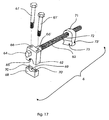
- the second variation of compression-distraction device 6 is based on plate-like elements coupled with threaded spindle and shown by figure 17 of enclosed drawing.
- the complex of device 6 consists of upper plate 62 with rotationally lying threaded spindle 63 whose rotation is performed by hexagonal head 64 leaned externally on plate 62.
- the upper plate 62 has on its top half-cylindrical gutter 65 and two vertically separated cylindrical holes 66, 66', designed for passage of screws 67 and 67' for connection with plate 68.
- the lower plate 68 has half-cylindrical gutter (identical to gutter 65) and two vertically separated threaded holes 70 and 70' that serve for connecting of both plates 62, 68, by screws 67, 67'.
- the upper and lower plate 68 and 69 are placed around bar 1 of fixator so that they are flanked by their gutters 65 and 69.
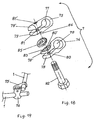
- figure 10 of drawing shows special double joint 7 for fixation of two bars 1 in various positions.
- the double joint has two joining parts 74 and 75 with cylindrically cut holes 76 and 77 through which two bars 1 can be introduced (see figure 19).
- the legs 78, 78' which are connected to hole 76, and legs 79, 79' of hole 77 have coaxial holes 80, 80' and 81, 81' that serve for screwing of screw 82.
- radial teething 83 is carried out; on leg 79, around hole 81 of joining part 75, similar teething has been carried out.
- the special double joint 7 is especially applicable in joining of two fixators; for instance, one used for fixation of lower leg fracture with other used for fixation of upper leg, which prevents all possible movements inside knee.
Landscapes
- Health & Medical Sciences (AREA)
- Orthopedic Medicine & Surgery (AREA)
- Life Sciences & Earth Sciences (AREA)
- Surgery (AREA)
- Medical Informatics (AREA)
- General Health & Medical Sciences (AREA)
- Biomedical Technology (AREA)
- Heart & Thoracic Surgery (AREA)
- Nuclear Medicine, Radiotherapy & Molecular Imaging (AREA)
- Molecular Biology (AREA)
- Animal Behavior & Ethology (AREA)
- Engineering & Computer Science (AREA)
- Public Health (AREA)
- Veterinary Medicine (AREA)
- Surgical Instruments (AREA)
- Acyclic And Carbocyclic Compounds In Medicinal Compositions (AREA)
- Pharmaceuticals Containing Other Organic And Inorganic Compounds (AREA)
- Saccharide Compounds (AREA)
- Polishing Bodies And Polishing Tools (AREA)
Claims (10)
- Ein externer Knochen-Fixierer, der mindestens zwei Pins (4) aufweist, die in jedem Hauptknochenfragment befestigbar sind, wobei der Knochenfixierer weiters für jeden Pin (4) einen Träger (2) aufweist, der eine Klemme (3) trägt, die den Pin (4) hält, wobei die Klemme (3) an dem Träger (2) derart montiert ist, dass zum Zweck der Justierung des Knochenfixierers eine Gleitbewegung der Klemme (3) entlang dem Träger (2) und eine Drehbewegung der Klemme (3) um den Träger (2) ermöglicht ist, und wobei der Träger (2) an einem Verbindungsstab (1) so befestigt ist, dass zum Zweck der Justierung des Knochenfixierers eine Gleitbewegung des Trägers (2) entlang dem Verbindungsstab (1) und eine Drehbewegung des Trägers (2) um den Verbindungsstab (1) ermöglicht ist, wobei der Verbindungsstab (1) zumindest zwei Träger (2) miteinander verbindet.
- Ein externer Knochen-Fixierer nach Anspruch 1 dadurch gekennzeichnet, dass der Träger (2) einen runden stabförmigen Körper (8) mit koaxial und integral verlaufendem zylindrischem Tragkopf (9) aufweist, wobei der Tragkopf (9) zweiseitige Löcher (10, 10') zur Aufnahme für den Verbindungsstab (1) aufweist, wobei eine Schraube (12) in den Tragkopf (9) eingedreht ist, wobei die Schraube ein Druck-Element (13) aufweist, welches einer profilierten, schlüssellochähnlichen Nut (14) an einem Schaft der Schraube (12) platziert ist, wobei das Druck-Element (13) einen zylinderförmigen Hals (15) aufweist, der an einem seiner Enden eine Kugel (16) und an seinem anderen Ende eine konkave Oberfläche aufweist, wobei der Durchmesser der konkaven Oberfläche (18) und der des Verbindungsstabs (1) identisch sind, wobei zwei Nasen (19, 19') auf einander gegenüberliegenden Oberflächenbereichen des Druck-Elements (13) zur Abstützung vertikaler Nuten (20, 20') im Inneren des zylinderförmigen Tragkopfes (9) vorgesehen sind, und wobei an einem freien Ende des stabförmigen Körpers (8) eine kleine Schraube (21) mit linsenförmigem Kopf eingedreht ist, wobei der Durchmesser des linsenförmigen Kopfes größer als der des stabförmigen Körpers (8) ist
- Ein externer Knochen-Fixierer nach Anspruch 2, dadurch gekennzeichnet, dass die Schraube (12A) des Trägers (2) ein Druck-Element (13A) mit einer konkaven Oberfläche und einer Kugel (16A) aufweist, wobei die Kugel einen Schlitz (24) aufweist, wobei die Kugel (16A), die durch eine schmalere Öffnung (22) gedrückt ist, in einem sphärischen Loch (23) platziert ist, das sich koaxial zu dem Hals der Schraube (12A) erstreckt.
- Ein externer Knochen-Fixierer nach einem der Ansprüche 1 bis 3, dadurch gekennzeichnet, dass der Träger (2A) einen runden, röhrenförmigen Körper (25) auf einem Ende und einen zylindrischen Tragkopf (27) mit einer kreisrunden Öffnung (28) für eine Schraube (29) mit einer konkaven Fläche, welche durch ein kreisförmiges Loch (28) gesteckt ist, befestigt, wobei die Schraube (29) eine rechtwinklige Form aufweist.
- Ein externer Knochen-Fixierer nach Anspruch 4, dadurch gekennzeichnet, dass der Träger (2B) an einem seiner Enden einen kugelförmigen Tragkopf (31) mit einer transversal durchgebohrten, zylindrischer Öffnung (32) für den Verbindungsstab (1), wobei die in der Längsrichtung verlaufenden Symmetrieachsen des röhrenförmigen Körpers (25) und der Öffnung (32) aufeinander senkrecht stehen, wobei in den röhrenförmigen Körper (25) eine lange Schraube (29) mit einem Druck-Element, welches die Form eines negativen Zylinders (13) aufweist und das zylindrische Loch penetriert, durch den röhrenförmigen Körper geschoben und eingedreht ist.
- Ein externer Knochen-Fixierer nach einem der Ansprüche 1 oder 2, dadurch gekennzeichnet, dass der Träger (2C) einen runden Stab (34) aufweist, auf welchem Stab (34) ein Tragkopf (35) in Form eines Parallelepipeds mit einer quer durchgebohrten zylindrischen Öffnung (36) für den Verbindungsstab (1) angeordnet ist, wobei an dem entgegengesetzten Ende des Tragkopfs (35), koaxial mit dem stabförmigen Körper (34), ein kürzerer Stab mit Gewinden (37) angeordnet ist, wobei die Achsen des Stabes mit Gewinde (37) und des Trägers (34) senkrecht auf der Längsachse der zylindrischen Öffnung (36) des Tragkopfes (35) stehen.
- Ein externer Knochen-Fixierer nach Anspruch 1 dadurch gekennzeichnet, dass die Klemme (3) des Knochen-Fixierer aus einer speziellen Schraube (38) mit beidseitig gekerbtem walzenförmigem Kopf (39) besteht, und dieser Kopf mit einer quer durchgebohrten zylindrischen Öffnung (40) für eine Anbringung an dem Körper (8) des Trägers oder am Verbindungstab (1) versehen ist, wobei ein Reiter (41), der mit seiner kalottenförmigen Fläche (42) in die zylindrische Öffnung (40) hineingeht, über einen gekerbten Teil des walzenförmigen Kopfes (39) der Schraube (38) gestreift ist, wobei nach dem Reiter (41) zwei teilweise verbundene kreisrund-ringförmige Platten (43) an der Schraube (38) angebracht sind, diese Platten haben auf der Verbindungsstelle eine geformte Nut (44) zur Anbringung an einem Pin (4), wobei die Platten (43) getrennt oder lose verbunden sein können, wobei die Auflagefläche des Reiters (41) und eine Platte (43) mit gezähnter Oberfläche (45, 46) durch die auf den Bolzen mit Gewinde (38) geschraubte Mutter (47) fest angezogen ist.
- Ein externer Knochen-Fixierer nach Anspruch 1, dadurch gekennzeichnet, dass er einen Träger (5) aufweist, der sich aus einem Zylinder (48) mit einem koaxial befestigten externen Stab (49) zusammensetzt, wobei sich eine längere Nut (50) oben auf dem Zylinder (48) befindet, wobei der Verbindungsstab (51) teilweise in den Zylinder (48) teleskopartig eingesetzt ist, wobei der Verbindungsstab (51) mit Hilfe von einer Schraube (52) durch die Nut (50) fest angezogen wird, wobei die Verbindungsstäbe (49, 51) den gleichen Durchmesser wie der Verbindungsstab (1) aufweisen, wobei eine Gleitvorrichtung (53) an dem Zylinder (48) mittels einer Schraube (54) befestigt ist, wobei an dem externen Verbindungsstab (51) eine mittels einer Schraube befestigte eine weitere Gleitvorrichtung (53) angeordnet ist, wobei Fortsätze (57, 57') der Gleitvorrichtungen (53, 55) mittels einer Gewindespindel (58) fixiert sind, wobei ein Kopf einer Schraube (59) in der Mitte der Gewindespindel (58) befstigt ist, und wobei eine Skala in der zwischen den Gleitvorrichtungen (53, 55) auf der Verbindungsstange (51) angeordnet ist, und dass ein Paar von Trägern (2) mit Klemmen (3), welche mit den Pins (4) eines Knochenfragmentes verbunden sind, auf die Verbindungsstange (49) geschoben ist, wohingegen ein andere Paar von Trägern (2) mit seinen Klemmen mit den Pins (4) eines anderen Hauptknochenfragmentes verbunden ist.
- Ein externer Knochen-Fixierer nach Anspruch 8, dadurch gekennzeichnet, dass er eine plattenförmigen Vorrichtung (6), die sich aus einer Oberplatte (62) mit drehbar gelagerter Schraubenspindel (63) mit sechskantigem Kopf (64) und einer Unterplatte (68) zusammensetzt, die halbzylindrische Öffnungen (65, 69) aufweist, zur Umschließung des Verbindungsstab (1), wobei die Platten (62, 68) mit den Schrauben (67, 67') durch die zylindrischen, auf der Oberplatte (62) befindlichen Öffnungen (66, 66') und durch die auf der Unterplatte (68) befindlichen Öffnungen mit Gewinden (70, 70') befestigt sind, wobei die Schraubenspindel (63) in die profilierte Platte (71) durch die Öffnung mit Gewinden (72) eingeschraubt ist, deren konkave Nuten (73, 73'), zum Stützen des runden Tragkopfes (9) des Trägers (2) dienen.
- Ein externer Knochen-Fixierer nach Anspruch 1, dadurch gekennzeichnet, dass er eine Doppelklemme (7) aufweist, die aus zwei Klemmen (74, 75) mit zylindrischen Öffnungen (76, 77) für Verbindungsstäbe (1) besteht, wobei die Öffnungen (76, 77) an einer Stelle so geschnitten sind, dass sich die Klemme (74) in zwei Schenkel (78, 78') und die Klemme (75) in zwei andere Schenkel (79, 79') teilt, durch die beiden Schenkel (78, 78') sind koaxial die kreisförmigen Öffnungen (80, 80') durchgebohrt, und durch die Schenkel (79, 79') sind auch die kreisförmigen Öffnungen (81, 81') durchgebohrt, wobei die runde Öffnung (81) mit Gewinde versehen ist; die Öffnungen (80', 81) durch die einander gegenüberliegenden Schenkel (78', 79) sind mit radial und strahlenförmig verlaufenden Zähnen (83, 84) versehen und zwischen ihnen wird ein beidseitig radial strahlenförmig gezähntes, rund-ringförmiges Plättchen (85) eingesetzt, die Schraube (82) zum Anziehen der Klemmen (74, 75) um die Verbindungsstäbe (1) ist durch die Öffnungen (80, 80'), durch das Plättchen (85) und durch die Öffnungen (81, 81') durchgezogen.
Applications Claiming Priority (3)
| Application Number | Priority Date | Filing Date | Title |
|---|---|---|---|
| YUP000801 | 2001-01-04 | ||
| YU801 | 2001-01-04 | ||
| PCT/YU2001/000030 WO2002053038A2 (en) | 2001-01-04 | 2001-11-30 | External skeletal fixator |
Publications (2)
| Publication Number | Publication Date |
|---|---|
| EP1351613A2 EP1351613A2 (de) | 2003-10-15 |
| EP1351613B1 true EP1351613B1 (de) | 2006-03-08 |
Family
ID=25547906
Family Applications (1)
| Application Number | Title | Priority Date | Filing Date |
|---|---|---|---|
| EP01995518A Expired - Lifetime EP1351613B1 (de) | 2001-01-04 | 2001-11-30 | Externer fixateur |
Country Status (5)
| Country | Link |
|---|---|
| EP (1) | EP1351613B1 (de) |
| AT (1) | ATE319379T1 (de) |
| AU (1) | AU2002226102A1 (de) |
| DE (1) | DE60117865T2 (de) |
| WO (1) | WO2002053038A2 (de) |
Cited By (3)
| Publication number | Priority date | Publication date | Assignee | Title |
|---|---|---|---|---|
| CN103417281A (zh) * | 2013-09-06 | 2013-12-04 | 江苏广济医疗科技有限公司 | 管状连接杆装置及骨外固定器 |
| CN103417280A (zh) * | 2013-09-06 | 2013-12-04 | 江苏广济医疗科技有限公司 | 管状牵伸加压连接杆控制装置及骨外固定器 |
| CN103445837A (zh) * | 2013-09-06 | 2013-12-18 | 江苏广济医疗科技有限公司 | 快速钢针固定夹及骨外固定器 |
Families Citing this family (11)
| Publication number | Priority date | Publication date | Assignee | Title |
|---|---|---|---|---|
| GB2414674B (en) | 2004-06-04 | 2009-08-12 | John Burke | Apparatus for the correction of skeletal deformities |
| DE102004056091B8 (de) | 2004-11-12 | 2007-04-26 | Aesculap Ag & Co. Kg | Orthopädische Fixationsvorrichtung und orthopädisches Fixationssystem |
| US7789895B2 (en) * | 2006-12-26 | 2010-09-07 | Warsaw Orthopedic, Inc. | Sacral reconstruction fixation device |
| US9474551B2 (en) | 2010-10-09 | 2016-10-25 | Universidad Del Valle | External fixation device adaptable for bone fractures |
| US9023045B2 (en) | 2010-10-28 | 2015-05-05 | Stryker Trauma Sa | Bolt and tool with anti-torque features |
| ES2426129T3 (es) * | 2010-10-28 | 2013-10-21 | Stryker Trauma Sa | Perno y herramienta con características de compensación del par |
| US9770272B2 (en) | 2012-12-12 | 2017-09-26 | Wright Medical Technology, Inc. | Orthopedic compression/distraction device |
| AU2014236355B2 (en) * | 2013-03-14 | 2016-10-06 | Wright Medical Technology, Inc. | Orthopedic compression/distraction device |
| CN107854170B (zh) * | 2017-11-14 | 2020-03-10 | 山东威高骨科材料股份有限公司 | 连接器及其锁定机构 |
| US11013545B2 (en) * | 2018-05-30 | 2021-05-25 | Acumed Llc | Distraction/compression apparatus and method for bone |
| CN112617990A (zh) * | 2019-09-24 | 2021-04-09 | 云南欧铂斯医疗科技有限公司 | 多臂多自由度骨折复位器 |
Family Cites Families (3)
| Publication number | Priority date | Publication date | Assignee | Title |
|---|---|---|---|---|
| US2393694A (en) * | 1945-04-10 | 1946-01-29 | Otto S Kirschner | Surgical apparatus |
| US4483334A (en) * | 1983-04-11 | 1984-11-20 | Murray William M | External fixation device |
| US4848368A (en) * | 1988-04-25 | 1989-07-18 | Kronner Richard F | Universal external fixation frame assembly |
-
2001
- 2001-11-30 DE DE60117865T patent/DE60117865T2/de not_active Expired - Lifetime
- 2001-11-30 AU AU2002226102A patent/AU2002226102A1/en not_active Abandoned
- 2001-11-30 WO PCT/YU2001/000030 patent/WO2002053038A2/en not_active Ceased
- 2001-11-30 AT AT01995518T patent/ATE319379T1/de not_active IP Right Cessation
- 2001-11-30 EP EP01995518A patent/EP1351613B1/de not_active Expired - Lifetime
Cited By (4)
| Publication number | Priority date | Publication date | Assignee | Title |
|---|---|---|---|---|
| CN103417281A (zh) * | 2013-09-06 | 2013-12-04 | 江苏广济医疗科技有限公司 | 管状连接杆装置及骨外固定器 |
| CN103417280A (zh) * | 2013-09-06 | 2013-12-04 | 江苏广济医疗科技有限公司 | 管状牵伸加压连接杆控制装置及骨外固定器 |
| CN103445837A (zh) * | 2013-09-06 | 2013-12-18 | 江苏广济医疗科技有限公司 | 快速钢针固定夹及骨外固定器 |
| CN103417280B (zh) * | 2013-09-06 | 2015-05-13 | 江苏广济医疗科技有限公司 | 管状牵伸加压连接杆控制装置及骨外固定器 |
Also Published As
| Publication number | Publication date |
|---|---|
| DE60117865D1 (de) | 2006-05-04 |
| DE60117865T2 (de) | 2006-11-16 |
| ATE319379T1 (de) | 2006-03-15 |
| WO2002053038A2 (en) | 2002-07-11 |
| EP1351613A2 (de) | 2003-10-15 |
| AU2002226102A1 (en) | 2002-07-16 |
| WO2002053038A3 (en) | 2002-09-12 |
Similar Documents
| Publication | Publication Date | Title |
|---|---|---|
| EP1351613B1 (de) | Externer fixateur | |
| US20220211415A1 (en) | External bone fixation system | |
| EP0216563B1 (de) | Externer Fixierungsapparat für Knochen | |
| CA2613278C (en) | Adjustable fixation clamp and method | |
| TWI362252B (de) | ||
| HU207654B (en) | Trowable device particularly for external fixing the fractures of small tubular bones | |
| CA2878967C (en) | Elongated pin for an external modular fixation system for temporary and/or permanent fixation applications and external modular fixation system | |
| US20070270808A1 (en) | Methods and devices for the interconnection of bone attachment devices | |
| JP6804546B2 (ja) | 創外固定支柱 | |
| US8262706B2 (en) | Device for creating a bone implant | |
| JP2003534092A (ja) | 使い捨ての外部固定器 | |
| WO1982002830A1 (en) | Colles fracture fixature device | |
| AU2007201380A1 (en) | Variable angle intramedullary nail | |
| EP1987792A1 (de) | Fixiervorrichtung, Kombination einer Fixiervorrichtung mit einem länglichen Element, Anordnung mit einer solchen Kombination sowie Osteosyntheseset | |
| CN104814779B (zh) | 一种可以多方向多角度调节的外固定架穿针夹具 | |
| BG112250A (bg) | Затягащи съединения за универсалнимодулнисистеми заостеосинтеза | |
| KR100595479B1 (ko) | 골절 체외고정장치 | |
| KR200301189Y1 (ko) | 골절 체외고정장치 | |
| US20240148412A1 (en) | Stable locking fixation of threaded bone pins and other components of ring external fixator | |
| US20090222006A1 (en) | External fixator | |
| DE10124994B4 (de) | Vorrichtung zur Fixierung von Knochen im Bereich des Handgelenks | |
| KR100411763B1 (ko) | 쐐기의 잠금작용을 이용한 체외고정기구 | |
| DE4226790C1 (en) | Osteo-synthetic stirrup clasp for fixing bone fragments - comprises fixation stirrup, fixation pin and connecting component together with guide socket | |
| SU1090378A1 (ru) | Устройство дл наружного чрескостного остеосинтеза | |
| BR112020026325A2 (pt) | Haste de conexão de fixação externa com atamento fêmea |
Legal Events
| Date | Code | Title | Description |
|---|---|---|---|
| PUAI | Public reference made under article 153(3) epc to a published international application that has entered the european phase |
Free format text: ORIGINAL CODE: 0009012 |
|
| 17P | Request for examination filed |
Effective date: 20030714 |
|
| AK | Designated contracting states |
Kind code of ref document: A2 Designated state(s): AT BE CH CY DE DK ES FI FR GB GR IE IT LI LU MC NL PT SE TR |
|
| AX | Request for extension of the european patent |
Extension state: AL LT LV MK RO SI |
|
| 17Q | First examination report despatched |
Effective date: 20040505 |
|
| GRAP | Despatch of communication of intention to grant a patent |
Free format text: ORIGINAL CODE: EPIDOSNIGR1 |
|
| GRAS | Grant fee paid |
Free format text: ORIGINAL CODE: EPIDOSNIGR3 |
|
| GRAA | (expected) grant |
Free format text: ORIGINAL CODE: 0009210 |
|
| AK | Designated contracting states |
Kind code of ref document: B1 Designated state(s): AT BE CH CY DE DK ES FI FR GB GR IE IT LI LU MC NL PT SE TR |
|
| AX | Request for extension of the european patent |
Extension state: SI |
|
| PG25 | Lapsed in a contracting state [announced via postgrant information from national office to epo] |
Ref country code: IT Free format text: LAPSE BECAUSE OF FAILURE TO SUBMIT A TRANSLATION OF THE DESCRIPTION OR TO PAY THE FEE WITHIN THE PRESCRIBED TIME-LIMIT;WARNING: LAPSES OF ITALIAN PATENTS WITH EFFECTIVE DATE BEFORE 2007 MAY HAVE OCCURRED AT ANY TIME BEFORE 2007. THE CORRECT EFFECTIVE DATE MAY BE DIFFERENT FROM THE ONE RECORDED. Effective date: 20060308 Ref country code: BE Free format text: LAPSE BECAUSE OF FAILURE TO SUBMIT A TRANSLATION OF THE DESCRIPTION OR TO PAY THE FEE WITHIN THE PRESCRIBED TIME-LIMIT Effective date: 20060308 Ref country code: NL Free format text: LAPSE BECAUSE OF FAILURE TO SUBMIT A TRANSLATION OF THE DESCRIPTION OR TO PAY THE FEE WITHIN THE PRESCRIBED TIME-LIMIT Effective date: 20060308 Ref country code: AT Free format text: LAPSE BECAUSE OF FAILURE TO SUBMIT A TRANSLATION OF THE DESCRIPTION OR TO PAY THE FEE WITHIN THE PRESCRIBED TIME-LIMIT Effective date: 20060308 Ref country code: FI Free format text: LAPSE BECAUSE OF FAILURE TO SUBMIT A TRANSLATION OF THE DESCRIPTION OR TO PAY THE FEE WITHIN THE PRESCRIBED TIME-LIMIT Effective date: 20060308 |
|
| REG | Reference to a national code |
Ref country code: GB Ref legal event code: FG4D |
|
| REG | Reference to a national code |
Ref country code: CH Ref legal event code: EP |
|
| REG | Reference to a national code |
Ref country code: IE Ref legal event code: FG4D |
|
| REF | Corresponds to: |
Ref document number: 60117865 Country of ref document: DE Date of ref document: 20060504 Kind code of ref document: P |
|
| PG25 | Lapsed in a contracting state [announced via postgrant information from national office to epo] |
Ref country code: DK Free format text: LAPSE BECAUSE OF FAILURE TO SUBMIT A TRANSLATION OF THE DESCRIPTION OR TO PAY THE FEE WITHIN THE PRESCRIBED TIME-LIMIT Effective date: 20060608 Ref country code: SE Free format text: LAPSE BECAUSE OF FAILURE TO SUBMIT A TRANSLATION OF THE DESCRIPTION OR TO PAY THE FEE WITHIN THE PRESCRIBED TIME-LIMIT Effective date: 20060608 |
|
| PG25 | Lapsed in a contracting state [announced via postgrant information from national office to epo] |
Ref country code: ES Free format text: LAPSE BECAUSE OF FAILURE TO SUBMIT A TRANSLATION OF THE DESCRIPTION OR TO PAY THE FEE WITHIN THE PRESCRIBED TIME-LIMIT Effective date: 20060619 |
|
| REG | Reference to a national code |
Ref country code: CH Ref legal event code: NV Representative=s name: ANDRE ROLAND S.A. |
|
| REG | Reference to a national code |
Ref country code: GR Ref legal event code: EP Ref document number: 20060401946 Country of ref document: GR |
|
| PG25 | Lapsed in a contracting state [announced via postgrant information from national office to epo] |
Ref country code: PT Free format text: LAPSE BECAUSE OF FAILURE TO SUBMIT A TRANSLATION OF THE DESCRIPTION OR TO PAY THE FEE WITHIN THE PRESCRIBED TIME-LIMIT Effective date: 20060808 |
|
| NLV1 | Nl: lapsed or annulled due to failure to fulfill the requirements of art. 29p and 29m of the patents act | ||
| ET | Fr: translation filed | ||
| PG25 | Lapsed in a contracting state [announced via postgrant information from national office to epo] |
Ref country code: IE Free format text: LAPSE BECAUSE OF NON-PAYMENT OF DUE FEES Effective date: 20061130 Ref country code: MC Free format text: LAPSE BECAUSE OF NON-PAYMENT OF DUE FEES Effective date: 20061130 |
|
| PLBE | No opposition filed within time limit |
Free format text: ORIGINAL CODE: 0009261 |
|
| STAA | Information on the status of an ep patent application or granted ep patent |
Free format text: STATUS: NO OPPOSITION FILED WITHIN TIME LIMIT |
|
| 26N | No opposition filed |
Effective date: 20061211 |
|
| PG25 | Lapsed in a contracting state [announced via postgrant information from national office to epo] |
Ref country code: TR Free format text: LAPSE BECAUSE OF FAILURE TO SUBMIT A TRANSLATION OF THE DESCRIPTION OR TO PAY THE FEE WITHIN THE PRESCRIBED TIME-LIMIT Effective date: 20060308 Ref country code: LU Free format text: LAPSE BECAUSE OF NON-PAYMENT OF DUE FEES Effective date: 20061130 |
|
| PG25 | Lapsed in a contracting state [announced via postgrant information from national office to epo] |
Ref country code: CY Free format text: LAPSE BECAUSE OF FAILURE TO SUBMIT A TRANSLATION OF THE DESCRIPTION OR TO PAY THE FEE WITHIN THE PRESCRIBED TIME-LIMIT Effective date: 20060308 |
|
| REG | Reference to a national code |
Ref country code: CH Ref legal event code: PCAR Free format text: ANDRE ROLAND S.A.;CASE POSTALE 5107;1002 LAUSANNE (CH) |
|
| REG | Reference to a national code |
Ref country code: FR Ref legal event code: PLFP Year of fee payment: 15 |
|
| PGFP | Annual fee paid to national office [announced via postgrant information from national office to epo] |
Ref country code: GB Payment date: 20151124 Year of fee payment: 15 |
|
| REG | Reference to a national code |
Ref country code: FR Ref legal event code: PLFP Year of fee payment: 16 |
|
| PGFP | Annual fee paid to national office [announced via postgrant information from national office to epo] |
Ref country code: FR Payment date: 20161125 Year of fee payment: 16 Ref country code: CH Payment date: 20161123 Year of fee payment: 16 |
|
| GBPC | Gb: european patent ceased through non-payment of renewal fee |
Effective date: 20161130 |
|
| PG25 | Lapsed in a contracting state [announced via postgrant information from national office to epo] |
Ref country code: GB Free format text: LAPSE BECAUSE OF NON-PAYMENT OF DUE FEES Effective date: 20161130 |
|
| PG25 | Lapsed in a contracting state [announced via postgrant information from national office to epo] |
Ref country code: LI Free format text: LAPSE BECAUSE OF NON-PAYMENT OF DUE FEES Effective date: 20171130 Ref country code: CH Free format text: LAPSE BECAUSE OF NON-PAYMENT OF DUE FEES Effective date: 20171130 |
|
| REG | Reference to a national code |
Ref country code: FR Ref legal event code: ST Effective date: 20180731 |
|
| PG25 | Lapsed in a contracting state [announced via postgrant information from national office to epo] |
Ref country code: FR Free format text: LAPSE BECAUSE OF NON-PAYMENT OF DUE FEES Effective date: 20171130 |
|
| PGFP | Annual fee paid to national office [announced via postgrant information from national office to epo] |
Ref country code: DE Payment date: 20181130 Year of fee payment: 18 Ref country code: GR Payment date: 20181130 Year of fee payment: 18 |
|
| PGFP | Annual fee paid to national office [announced via postgrant information from national office to epo] |
Ref country code: IT Payment date: 20181130 Year of fee payment: 18 |
|
| REG | Reference to a national code |
Ref country code: DE Ref legal event code: R119 Ref document number: 60117865 Country of ref document: DE |
|
| PG25 | Lapsed in a contracting state [announced via postgrant information from national office to epo] |
Ref country code: GR Free format text: LAPSE BECAUSE OF NON-PAYMENT OF DUE FEES Effective date: 20200609 |
|
| PG25 | Lapsed in a contracting state [announced via postgrant information from national office to epo] |
Ref country code: IT Free format text: LAPSE BECAUSE OF NON-PAYMENT OF DUE FEES Effective date: 20191130 Ref country code: DE Free format text: LAPSE BECAUSE OF NON-PAYMENT OF DUE FEES Effective date: 20200603 |