EP1350908A2 - Système de contrôle pour une serrure de véhicule - Google Patents
Système de contrôle pour une serrure de véhicule Download PDFInfo
- Publication number
- EP1350908A2 EP1350908A2 EP03252090A EP03252090A EP1350908A2 EP 1350908 A2 EP1350908 A2 EP 1350908A2 EP 03252090 A EP03252090 A EP 03252090A EP 03252090 A EP03252090 A EP 03252090A EP 1350908 A2 EP1350908 A2 EP 1350908A2
- Authority
- EP
- European Patent Office
- Prior art keywords
- latch
- controller
- control system
- malfunction
- sensor
- Prior art date
- Legal status (The legal status is an assumption and is not a legal conclusion. Google has not performed a legal analysis and makes no representation as to the accuracy of the status listed.)
- Withdrawn
Links
- 230000007257 malfunction Effects 0.000 claims abstract description 30
- 238000000034 method Methods 0.000 claims description 8
- 230000004044 response Effects 0.000 claims description 2
- 230000007547 defect Effects 0.000 claims 1
- 210000000078 claw Anatomy 0.000 description 17
- 230000007246 mechanism Effects 0.000 description 15
- 238000010586 diagram Methods 0.000 description 9
- 230000008859 change Effects 0.000 description 6
- 230000000694 effects Effects 0.000 description 4
- 230000011664 signaling Effects 0.000 description 3
- 230000005540 biological transmission Effects 0.000 description 2
- 230000009347 mechanical transmission Effects 0.000 description 2
- 238000012544 monitoring process Methods 0.000 description 2
- 230000001960 triggered effect Effects 0.000 description 2
- 230000000295 complement effect Effects 0.000 description 1
- 238000010276 construction Methods 0.000 description 1
- 230000003111 delayed effect Effects 0.000 description 1
- 238000001514 detection method Methods 0.000 description 1
- JEIPFZHSYJVQDO-UHFFFAOYSA-N iron(III) oxide Inorganic materials O=[Fe]O[Fe]=O JEIPFZHSYJVQDO-UHFFFAOYSA-N 0.000 description 1
- 230000002265 prevention Effects 0.000 description 1
- 230000008569 process Effects 0.000 description 1
Images


Classifications
-
- E—FIXED CONSTRUCTIONS
- E05—LOCKS; KEYS; WINDOW OR DOOR FITTINGS; SAFES
- E05B—LOCKS; ACCESSORIES THEREFOR; HANDCUFFS
- E05B81/00—Power-actuated vehicle locks
- E05B81/54—Electrical circuits
- E05B81/64—Monitoring or sensing, e.g. by using switches or sensors
- E05B81/70—Monitoring or sensing, e.g. by using switches or sensors the wing position
-
- E—FIXED CONSTRUCTIONS
- E05—LOCKS; KEYS; WINDOW OR DOOR FITTINGS; SAFES
- E05B—LOCKS; ACCESSORIES THEREFOR; HANDCUFFS
- E05B81/00—Power-actuated vehicle locks
- E05B81/54—Electrical circuits
- E05B81/64—Monitoring or sensing, e.g. by using switches or sensors
- E05B81/66—Monitoring or sensing, e.g. by using switches or sensors the bolt position, i.e. the latching status
-
- E—FIXED CONSTRUCTIONS
- E05—LOCKS; KEYS; WINDOW OR DOOR FITTINGS; SAFES
- E05B—LOCKS; ACCESSORIES THEREFOR; HANDCUFFS
- E05B77/00—Vehicle locks characterised by special functions or purposes
- E05B77/46—Locking several wings simultaneously
- E05B77/48—Locking several wings simultaneously by electrical means
Definitions
- the present invention relates to a control system for a vehicle door latch. More particularly, the present invention relates to a closed loop control system for a vehicle door latch.
- the controller merely decides that user intervention has caused failure of an operation to be carried out, rather than a malfunction.
- An example of such a situation is a user signalling the locking of all latches on a vehicle with power door locking, but one of the latches failing to lock being interpreted by the latch control system as an immediate user signal to then unlock all of the latches, including those that have successfully locked. In turn, this may result in a vehicle user being unaware of the fault resulting in a compromising of vehicle security or safety, and/or damage of the latch occurring.
- instructions received by the controller may be outside the parameters of operation of the latch or physical limitations of the latch, such that attempts by the latch to carry out the instructions result in a malfunction due to an incorrectly timed sequence of operations being performed within the latch.
- malfunction should be understood to mean a specific fault with a latch component such as a non-functioning motor or a seized lever, or a non-functioning component due to its movement being prevented by a blockage because a further component is incorrectly positioned (e.g. because a latch has been instructed to carry out a sequence of operations too rapidly for a motor to complete one operation before another operation starts).
- the present invention seeks to overcome, or at least mitigate, the problems of the prior art.
- a closed loop control system for a vehicle door latch comprising a controller, a latch including at least one sensor and at least one power actuator, the system being capable of detecting when the latch has failed or will fail to carry out an instruction from the controller due to a latch malfunction and is configured so as to attempt to prevent or overcome the malfunction or is configured to generate an error signal.
- Another aspect of the present invention provides a method of controlling a closed loop control system comprising a controller and a vehicle door latch including at least one sensor and at least one power actuator comprising the steps of:
- a further aspect of the present invention provides a method of controlling a closed loop control system comprising a controller and a vehicle door latch including at least one sensor and at least one power actuator comprising the steps of:
- a control system 10 for a vehicle door latch 12 is illustrated schematically. Mechanical connections are illustrated by arrows with solid lines and electrical connections by arrows with broken lines.
- An inside door handle (IDH) 14 fitted to the interior face of a vehicle door (not shown) is operably connected to inside release lever (IRL) 16 of the latch by a mechanical connection such as a cable or rod.
- the inside release lever is coupled to an intermediate release lever 25 via a locking mechanism 18.
- the intermediate release lever 25 is coupled to a pawl 20 arranged to releasably retain a latch bolt in the form of a rotatable claw 22.
- Claw 22 is provided with pawl abutments (not shown) representing first safety and fully latched positions of the claw when the abutments are engaged by pawl 20.
- a power actuator in the form of a motor 26 is provided. Additionally, the latch may be locked manually by using a conventional key, for example. Instructions in the form of electrical signals for the motor 26 to change the state of mechanism 18 between a locked and unlocked state are provided by a controller 30 remote from the latch 12.
- the controller 30 is preferably in the form of a micro-processor and may, in other embodiments, be integrated into the latch 12.
- power actuator is intended to mean any form of motor powered by a vehicle power source such as the battery, and that this term specifically excludes actuators such as handles where the power source is, in effect, the vehicle user.
- An outside door handle 31 mounted on an outer face of the vehicle door is operably connected to an outside release lever 34 which is in turn operably connected to pawl 20 via a locking mechanism 36.
- a block or break may be provided in the transmission path through mechanism 36 by motor 38, with this block or break representing the mechanism being locked from the outside. Motor 38 is again controlled by controller 30.
- the latch is provided with two switches.
- the first of these is an inside release lever (IRL) switch 24 that signals controller 30 when the inside door handle 14 and hence inside release lever 16 are being actuated by a vehicle user.
- the IRL switch 24 also signals the controller when the intermediate release lever is actuated independently of the inside release lever.
- the second is a door ajar (DA) switch 28 which is associated with claw 22 and signals the controller 30 when the claw has been released from its fully latched position.
- DA door ajar
- the switch is triggered when the claw has rotated to a position approximately half-way between the fully latched and first safety abutments.
- a power release actuator 32 having an actuator motor 33 is also associated with the latch 12.
- the actuator 32 receives the appropriate signal from controller 30, it drives the release lever 25 to lift pawl 20 out of engagement with claw 22, thereby releasing the latch.
- release of the latch is achieved by use of the power release actuator 32.
- the mechanical transmission paths from handles 14 and 31 to the pawl 20 are provided as a back-up, should power be cut to the latch due to an accident or flat battery, for example.
- FIG 2 the operation of the latch 12 in response to output signals received from door ajar switch 28 and inside release switch 24 is shown. It can be seen that the logic of the controller 30 is able to interpret every possible combination of outputs from the door ajar switch 28 and inside release switch 24 (including changes of output from 0 to 1 and 1 to 0) to be a particular state of the latch 12 and hence the associated door (not shown).
- controller 30 may signal one of more of motors 26 and 38 and power release actuator motor 33 in order to unlock the latch 12 or provide for the power release of the latch.
- the controller 30 logic has been programmed to provide for a two pull override function for the inside door handle 14. This means that a first pull of the inside door handle 14 will cause a signal to be sent from inside release switch 24 to the controller 30, which in turn signals motors 26 and 38 to cause the block or break in mechanisms 18 and 36 respectively to be removed.
- the controller stores the fact that the inside door handle has been pulled once. If the inside door handle 14 is then pulled a second time, the controller determines that the latch 12 should be released and accordingly signals the power release actuator motor 33 to lift pawl 20. If the power release operation fails the latch may be released via the mechanical linkage from the handles 14, 31 to the pawl 20. This may require a greater force to be exerted by a vehicle user on the inside door handle 14 or outside door handle 31 to achieve unlatching.
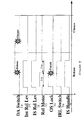
- the normal mode of operation of the latch 12 is illustrated by the time line diagram of Figure 3.
- the latch starts in a latched and unlocked state.
- the lines represent the position of the inside handle 14 and inside release lever 16 and intermediate release lever 25, the output signals of switches 24 and 28 and the voltage applied to the power release actuator motor 33. All of the various switches, motors and levers start in a rest position.
- the inside release lever switch 24 emits an output corresponding to the "1" state of Figure 2.
- the controller signals the power release actuator motor 33, which acts on pawl 20 to release the claw 22.
- rotation of the claw causes the door ajar switch 28 to signal the controller 30 that the latch 12 is released, once the claw 22 has rotated to be between the fully latched and first safety positions.
- the controller 30 signals the power release actuator motor 33 to back drive to its normal rest position.
- the vehicle user simply slams the door shut.
- the engagement of the claw 22 with a corresponding striker (not shown) on the door surround (not shown) causes the claw to rotate back to its latched position with the door ajar switch 28 indicating that closure has been achieved.
- the normal sequence of operation of the latch is shown in broken lines with the actual position/state of each component shown in unbroken lines.
- the intermediate release lever 25 remains in an actuated state despite the inside door handle 14 having been released. This may occur due to the internal release lever 16 being jammed because of rust, ice, or dirt ingress or the like or because motor 33 which drives the intermediate release lever continues to be powered due to a malfunction. Since the intermediate release lever remains actuated, pawl 20 cannot engage either claw abutment when an attempt is made to latch the latch. This means that whilst the door ajar switch may detect closure, latching will not have successfully occurred in this condition.
- the "jammed" condition is illustrated by line B of release motor voltage.
- a timer is provided in controller 30. Once the controller determines that the inside release switch 24 continues to emit a high output after a predetermined time, the controller generates an error code that may be sent to the vehicle diagnostic system and/or a dashboard warning light or a buzzer, for example. Alternatively, an error code may be generated as a result of a continued high output from inside release switch 24 whilst door ajar switch 28 indicates closure of the latch. Thus, even though correct operation of the latch is prevented, vehicle users are alerted to the malfunction and can take appropriate steps to rectify it.
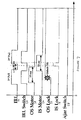
- FIG. 5 a variant of the control system is shown in which the latch 12 is provided with a single pull override unlocking function.
- the user pulls inside handle 14, triggering inside release lever 16 and intermediate release lever 25, which in turn causes inside release switch 24 to emit a high output.
- the controller 30 is programmed to simultaneously signal the unlocking of outside lock 36 and to signal the release motor 33 to lift the pawl 20 from claw 22, thereby releasing the latch.
- the controller signals the back-driving of release motor 33 to its rest position.
- Once intermediate release lever is back in its rest position, the inside lock 18 is unlocked by motor 26. By delaying this until after release has occurred, the release process may occur more quickly. Thereafter, the door may be slammed shut as before, returning to a latched but unlocked state.
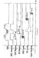
- FIG. 6 another embodiment of the control system for use with latch 12 is illustrated, which may be complementary with the control system of the first embodiment.
- the latch 12 starts in a locked condition.
- a first pull of inside release lever 16 causes inside release switch 24 to emit a high output.
- This output is processed by controller 30 whose logic determines that the first pull should result in outside motor 38 and inside motor 26 being signalled to unlock the inside and outside lock mechanisms 18 and 36 from inside door handle 31 and inside door handle 14 respectively.
- inside release lever 16 must return to its rest position, whereas unlocking of outside lock mechanism 36 may occur at any time.
- both outside and inside lock mechanisms 36 and 18 change to an unlocked state, but with the unlocking of inside unlocking mechanism 18 being slightly delayed.
- latch 12 is not fitted with a control system of this embodiment of the present invention and furthermore time x between the first and second pulls of the inside door handle 14 is less than 50 milliseconds.
- time x between the first and second pulls of the inside door handle 14 is less than 50 milliseconds.
- the inside lock 18 because of the construction of the latch mechanism, it is not possible for the inside lock 18 to be unlocked whilst the inside door handle 14 is being pulled.
- the operation of unlocking the inside lock 18 fails and the second pull thus does not result in the release of the latch, as reflected by a continued low output from door ajar switch 28.
- FIG 8 illustrates a functioning of a latch 12 to which the control system of the present embodiment has been fitted.
- the time X between the first and second pulls is less than 50 milliseconds, meaning that unlocking of inside lock mechanism 18 fails as in Figure 7.
- controller 30 is programmed to expect to receive an output from door ajar switch 28 shortly after the second pull (as represented by broken line 40).
- the logic of controller 30 recognises the unlocking malfunction and signals inside motor 26 a second time to unlock inside lock 18, before signalling power release actuator 32 (not shown in Figure 8) to effect release of claw 22 thereby causing ajar switch 28 to emit a high output.
- the inside handle 14 may be pulled a third time to release the claw 22 manually.
- the controller determines that an instruction from a vehicle user will cause a malfunction in a latch prior to instructing the latch to perform a function (e.g. because it has stored the time an actuator requires to perform a certain function) and is programmed to delay one or more steps in a sequence of instructions to prevent such a malfunction occurring.
- a typical latch may be fitted with or have associated therewith the one or more of the following further switches in addition to the internal release switch 24 and door ajar switch 28: a lock status indicator switch, central door locking switch, superlock switch, release switch, closure switch interior light (often fitted to striker or hinge face of door), child safety switch, as well as two switches per motor that are triggered at the extremes of the motor's drive.
- latches may be fitted with the following further actuators: superlocking, closure and child safety.
- a complete closed loop control system may be provided that may be capable of performing vehicle security functions, vehicle safety functions, latch diagnostic functions, vehicle comfort functions as well as determining when the change of state of various latch components should be effected by one or more of the actuators described above.
- the present invention also relates to a method of controlling a latch using a closed loop control system. It should be noted that whilst the system has been described in relation to the control of a single latch, it may be employed in relation to more than one latch on the same vehicle.
Landscapes
- Lock And Its Accessories (AREA)
Applications Claiming Priority (2)
| Application Number | Priority Date | Filing Date | Title |
|---|---|---|---|
| GB0207526 | 2002-04-02 | ||
| GBGB0207526.5A GB0207526D0 (en) | 2002-04-02 | 2002-04-02 | Control system for a vehicle door latch |
Publications (2)
| Publication Number | Publication Date |
|---|---|
| EP1350908A2 true EP1350908A2 (fr) | 2003-10-08 |
| EP1350908A3 EP1350908A3 (fr) | 2006-01-04 |
Family
ID=9934046
Family Applications (1)
| Application Number | Title | Priority Date | Filing Date |
|---|---|---|---|
| EP03252090A Withdrawn EP1350908A3 (fr) | 2002-04-02 | 2003-04-02 | Système de contrôle pour une serrure de véhicule |
Country Status (3)
| Country | Link |
|---|---|
| US (1) | US20030182863A1 (fr) |
| EP (1) | EP1350908A3 (fr) |
| GB (1) | GB0207526D0 (fr) |
Cited By (2)
| Publication number | Priority date | Publication date | Assignee | Title |
|---|---|---|---|---|
| WO2005008002A2 (fr) * | 2003-07-09 | 2005-01-27 | Siemens Vdo Automotive Corporation | Systeme de commande de vehicule pour porte electrique |
| US11549287B2 (en) | 2019-12-04 | 2023-01-10 | Kiekert Ag | Door latch, in particular motor vehicle door latch |
Families Citing this family (38)
| Publication number | Priority date | Publication date | Assignee | Title |
|---|---|---|---|---|
| JP3650375B2 (ja) * | 2002-05-21 | 2005-05-18 | アイシン精機株式会社 | 車体用ドア装置 |
| EP1371802A3 (fr) * | 2002-06-12 | 2006-05-24 | Brose Schliesssysteme GmbH & Co. KG | Serrure de porte pour véhicule automobile avec condamnation centrale actionnée électromécaniquement |
| US7221255B2 (en) * | 2004-03-02 | 2007-05-22 | Honeywell International Inc. | Embedded automotive latch communications protocol |
| US20050216133A1 (en) * | 2004-03-25 | 2005-09-29 | Macdougall Lonny | Child lock indicator |
| US7218206B2 (en) * | 2004-04-14 | 2007-05-15 | Honeywell International Inc. | Automotive latch debug and diagnostic user interface |
| US20050280501A1 (en) * | 2004-06-21 | 2005-12-22 | Honeywell International, Inc. | Automotive latch and RF system interfacing |
| US7075416B2 (en) * | 2004-06-21 | 2006-07-11 | Honeywell International Inc. | Automotive universal latch control implementation |
| US20060010943A1 (en) * | 2004-07-13 | 2006-01-19 | Lear Corporation | Mechanical handle switch assembly |
| US7170253B2 (en) * | 2004-07-27 | 2007-01-30 | Honeywell International Inc. | Automotive door latch control by motor current monitoring |
| KR100694448B1 (ko) | 2006-05-24 | 2007-03-12 | 대기오토모티브 주식회사 | 도어 래치의 디텐트 스위치 내장 구조 |
| US20070273478A1 (en) * | 2006-05-26 | 2007-11-29 | John Phillip Chevalier | Automotive latch and RF system interfacing |
| US20070274695A1 (en) * | 2006-05-26 | 2007-11-29 | John Phillip Chevalier | Automotive universal latch control implementation |
| GB2451820B (en) * | 2007-08-11 | 2012-05-16 | Body Systems Usa Llc | Vehicle door latch system |
| US9260882B2 (en) | 2009-03-12 | 2016-02-16 | Ford Global Technologies, Llc | Universal global latch system |
| US9080355B2 (en) * | 2009-12-18 | 2015-07-14 | Brose Schliesssysteme Gmbh & Co. Kg | Circuit and method for preventing inadvertent opening of a vehicle door |
| US9103143B2 (en) | 2011-09-26 | 2015-08-11 | Tesla Motors, Inc. | Door handle apparatus for vehicles |
| US9080352B2 (en) * | 2011-09-26 | 2015-07-14 | Tesla Motors, Inc. | Controller apparatus and sensors for a vehicle door handle |
| US9551166B2 (en) | 2011-11-02 | 2017-01-24 | Ford Global Technologies, Llc | Electronic interior door release system |
| US8648689B2 (en) | 2012-02-14 | 2014-02-11 | Ford Global Technologies, Llc | Method and system for detecting door state and door sensor failures |
| US9416565B2 (en) | 2013-11-21 | 2016-08-16 | Ford Global Technologies, Llc | Piezo based energy harvesting for e-latch systems |
| DE102014100927A1 (de) * | 2014-01-28 | 2015-07-30 | Dr. Ing. H.C. F. Porsche Aktiengesellschaft | Verfahren zur Überwachung eines Türkontaktschalter einer Fahrertür eines Kraftfahrzeugs |
| US10323442B2 (en) | 2014-05-13 | 2019-06-18 | Ford Global Technologies, Llc | Electronic safe door unlatching operations |
| US10273725B2 (en) | 2014-05-13 | 2019-04-30 | Ford Global Technologies, Llc | Customer coaching method for location of E-latch backup handles |
| US9903142B2 (en) | 2014-05-13 | 2018-02-27 | Ford Global Technologies, Llc | Vehicle door handle and powered latch system |
| US10119308B2 (en) | 2014-05-13 | 2018-11-06 | Ford Global Technologies, Llc | Powered latch system for vehicle doors and control system therefor |
| US9909344B2 (en) | 2014-08-26 | 2018-03-06 | Ford Global Technologies, Llc | Keyless vehicle door latch system with powered backup unlock feature |
| DE102015203421A1 (de) * | 2015-02-26 | 2016-09-01 | Schaeffler Technologies AG & Co. KG | Anordnung für eine Zentralverriegelung eines Fahrzeugs und Verfahren zum Betrieb einer Anordnung für eine Zentralverriegelung eines Fahrzeugs |
| US9707889B2 (en) * | 2015-06-03 | 2017-07-18 | GM Global Technology Operations LLC | Method of controlling a vehicle door lock system |
| US9725069B2 (en) | 2015-10-12 | 2017-08-08 | Ford Global Technologies, Llc | Keyless vehicle systems |
| US10227810B2 (en) | 2016-08-03 | 2019-03-12 | Ford Global Technologies, Llc | Priority driven power side door open/close operations |
| US10087671B2 (en) | 2016-08-04 | 2018-10-02 | Ford Global Technologies, Llc | Powered driven door presenter for vehicle doors |
| US10329823B2 (en) | 2016-08-24 | 2019-06-25 | Ford Global Technologies, Llc | Anti-pinch control system for powered vehicle doors |
| US10458171B2 (en) | 2016-09-19 | 2019-10-29 | Ford Global Technologies, Llc | Anti-pinch logic for door opening actuator |
| JP6992263B2 (ja) * | 2017-03-17 | 2022-01-13 | 株式会社アイシン | 車両用開閉体制御装置 |
| US10604970B2 (en) * | 2017-05-04 | 2020-03-31 | Ford Global Technologies, Llc | Method to detect end-of-life in latches |
| US10907386B2 (en) | 2018-06-07 | 2021-02-02 | Ford Global Technologies, Llc | Side door pushbutton releases |
| DE102018120447A1 (de) * | 2018-08-22 | 2020-02-27 | Kiekert Ag | Verfahren zur Steuerung eines Kraftfahrzeugschlosses |
| DE102020110769A1 (de) | 2020-04-21 | 2021-10-21 | Daimler Ag | Verfahren zur sicheren Erkennung einer Schließposition eines beweglichen Teils von einem Fahrzeug |
Citations (5)
| Publication number | Priority date | Publication date | Assignee | Title |
|---|---|---|---|---|
| EP0528317A1 (fr) * | 1991-08-09 | 1993-02-24 | Bayerische Motoren Werke Aktiengesellschaft | Dispositif de commande d'un véhicule automobile |
| US5992194A (en) * | 1995-12-20 | 1999-11-30 | Vdo Adolf Schindling Ag | Device for unlocking doors |
| EP1008711A1 (fr) * | 1998-12-07 | 2000-06-14 | Automobiles Peugeot | Système de commande de l'état de condamnation/décondamnation d'une serrure motorisée pour véhicule automobile |
| EP1060922A1 (fr) * | 1999-06-19 | 2000-12-20 | Brose Fahrzeugteile GmbH & Co. KG | Circuit de commande de lève-vitre électrique, de toit coulissant, ou de serrure automatique pour portes pour véhicule automobile |
| DE10015646A1 (de) * | 2000-03-29 | 2001-10-11 | Bosch Gmbh Robert | Vorrichtung zur Benutzerwarnung in einem Kraftfahrzeug |
Family Cites Families (16)
| Publication number | Priority date | Publication date | Assignee | Title |
|---|---|---|---|---|
| JP2546842B2 (ja) * | 1987-06-16 | 1996-10-23 | 日産自動車株式会社 | 車両用施解錠制御装置 |
| DE8809256U1 (de) * | 1988-07-20 | 1988-09-22 | Kiekert GmbH & Co KG, 5628 Heiligenhaus | Kraftfahrzeugtürverschluß mit in der Kraftfahrzeugtür untergebrachtem Schloß und Kindersicherung |
| GB2276913B (en) * | 1993-04-07 | 1996-08-07 | Mitsui Mining & Smelting Co | Door lock apparatus with automatic door closing mechanism |
| DE4432799C2 (de) * | 1994-09-15 | 1996-09-05 | Kiekert Ag | Antrieb für eine Kindersicherungseinrichtung in einem Kraftfahrzeugtürverschluß |
| GB2300875B (en) * | 1995-05-13 | 1998-11-04 | Rockwell Body & Chassis Syst | Vehicle door latch assembly |
| US5961163A (en) * | 1995-09-08 | 1999-10-05 | Kiekert Ag | Motor-vehicle door latch with antitheft protection |
| EP0960246B1 (fr) * | 1997-02-04 | 2005-08-31 | Intier Automotive Closures Inc. | Systeme de verrouillage pour portiere de vehicule avec mecanismes electriques de verrouillage interieur et exterieur de la portiere |
| US6236333B1 (en) * | 1998-06-17 | 2001-05-22 | Lear Automotive Dearborn, Inc. | Passive remote keyless entry system |
| US6010165A (en) * | 1998-09-21 | 2000-01-04 | General Motors Corporation | Door latch with child security lock and unlocking assembly |
| FR2785637B1 (fr) * | 1998-11-09 | 2000-12-29 | Valeo Securite Habitacle | Serrure de porte de vehicule automobile a condamnation/decondamnation electrique |
| US6199923B1 (en) * | 1999-06-10 | 2001-03-13 | Delphi Technologies, Inc. | Vehicle door latch |
| US6776442B2 (en) * | 2001-01-09 | 2004-08-17 | Strattec Security Corporation | Latch apparatus and method |
| DE60220328T2 (de) * | 2001-03-28 | 2008-01-24 | Aisin Seiki K.K., Kariya | Betätigungsvorrichtung eines Fahrzeugtürschlosses |
| GB2381034B (en) * | 2001-07-04 | 2005-02-16 | John Phillip Chevalier | Closure control apparatus comprising latch arrangement |
| GB0201547D0 (en) * | 2002-01-24 | 2002-03-13 | Meritor Light Vehicle Sys Ltd | Vehicle access control and start system |
| FR2835867B1 (fr) * | 2002-02-12 | 2004-08-20 | Meritor Light Vehicle Sys Ltd | Serrure de vehicule automobile |
-
2002
- 2002-04-02 GB GBGB0207526.5A patent/GB0207526D0/en not_active Ceased
-
2003
- 2003-04-02 EP EP03252090A patent/EP1350908A3/fr not_active Withdrawn
- 2003-04-02 US US10/405,911 patent/US20030182863A1/en not_active Abandoned
Patent Citations (5)
| Publication number | Priority date | Publication date | Assignee | Title |
|---|---|---|---|---|
| EP0528317A1 (fr) * | 1991-08-09 | 1993-02-24 | Bayerische Motoren Werke Aktiengesellschaft | Dispositif de commande d'un véhicule automobile |
| US5992194A (en) * | 1995-12-20 | 1999-11-30 | Vdo Adolf Schindling Ag | Device for unlocking doors |
| EP1008711A1 (fr) * | 1998-12-07 | 2000-06-14 | Automobiles Peugeot | Système de commande de l'état de condamnation/décondamnation d'une serrure motorisée pour véhicule automobile |
| EP1060922A1 (fr) * | 1999-06-19 | 2000-12-20 | Brose Fahrzeugteile GmbH & Co. KG | Circuit de commande de lève-vitre électrique, de toit coulissant, ou de serrure automatique pour portes pour véhicule automobile |
| DE10015646A1 (de) * | 2000-03-29 | 2001-10-11 | Bosch Gmbh Robert | Vorrichtung zur Benutzerwarnung in einem Kraftfahrzeug |
Cited By (3)
| Publication number | Priority date | Publication date | Assignee | Title |
|---|---|---|---|---|
| WO2005008002A2 (fr) * | 2003-07-09 | 2005-01-27 | Siemens Vdo Automotive Corporation | Systeme de commande de vehicule pour porte electrique |
| WO2005008002A3 (fr) * | 2003-07-09 | 2005-03-10 | Siemens Vdo Automotive Corp | Systeme de commande de vehicule pour porte electrique |
| US11549287B2 (en) | 2019-12-04 | 2023-01-10 | Kiekert Ag | Door latch, in particular motor vehicle door latch |
Also Published As
| Publication number | Publication date |
|---|---|
| GB0207526D0 (en) | 2002-05-08 |
| EP1350908A3 (fr) | 2006-01-04 |
| US20030182863A1 (en) | 2003-10-02 |
Similar Documents
| Publication | Publication Date | Title |
|---|---|---|
| EP1350908A2 (fr) | Système de contrôle pour une serrure de véhicule | |
| US11732514B2 (en) | Closure latch assembly with a power release mechanism and an inside handle release mechanism | |
| EP1288410B1 (fr) | Dispositif de verrouillage pour porte | |
| EP1296010B1 (fr) | Mécanisme pour l'ouverture et la fermeture d'une porte | |
| CN110230441B (zh) | 动力闩锁组件 | |
| CN113692472B (zh) | 用于机动车车门的锁闭装置 | |
| US10655368B2 (en) | Electrical door latch with motor reset | |
| US7642669B2 (en) | Electrical circuit arrangement | |
| US5613716A (en) | Electronic vehicle door unlatch control | |
| EP1473428B1 (fr) | Un méchanisme de verrouillage | |
| US6112564A (en) | Lock, in particular for motor vehicle doors | |
| US6974165B2 (en) | Door lock apparatus for a vehicle | |
| CN111335756B (zh) | 具有与释放机构柔性连接的双掣爪闩锁机构的智能闩锁组件 | |
| JP6716827B2 (ja) | 自動車ドアラッチ | |
| EP1347133A2 (fr) | Dispositif d'ouverture d'une serrure de porte | |
| CN107849873B (zh) | 用于控制机动车门锁的方法 | |
| JP2003269029A (ja) | 自動車用ドアロック | |
| CN110397357B (zh) | 与车门中的闭合闩锁组件一起使用的远程双锁组件 | |
| US20010052705A1 (en) | Latch assembly and vehicle including such a latch assembly | |
| US11542730B2 (en) | Closure latch assembly with a power release mechanism and motor control system | |
| CN1963125A (zh) | 闩锁装置 | |
| EP1464779B1 (fr) | Verrou | |
| US20030218340A1 (en) | Latch arrangement | |
| EP1522663A2 (fr) | Serrure de porte véhicule avec un actionneur | |
| CN116181164A (zh) | 具有提供多个动力功能的动力操作致动器的闭合闩锁组件 |
Legal Events
| Date | Code | Title | Description |
|---|---|---|---|
| PUAI | Public reference made under article 153(3) epc to a published international application that has entered the european phase |
Free format text: ORIGINAL CODE: 0009012 |
|
| AK | Designated contracting states |
Kind code of ref document: A2 Designated state(s): AT BE BG CH CY CZ DE DK EE ES FI FR GB GR HU IE IT LI LU MC NL PT RO SE SI SK TR |
|
| AX | Request for extension of the european patent |
Extension state: AL LT LV MK |
|
| PUAL | Search report despatched |
Free format text: ORIGINAL CODE: 0009013 |
|
| AK | Designated contracting states |
Kind code of ref document: A3 Designated state(s): AT BE BG CH CY CZ DE DK EE ES FI FR GB GR HU IE IT LI LU MC NL PT RO SE SI SK TR |
|
| AX | Request for extension of the european patent |
Extension state: AL LT LV MK |
|
| 17P | Request for examination filed |
Effective date: 20060609 |
|
| AKX | Designation fees paid |
Designated state(s): DE FR GB |
|
| STAA | Information on the status of an ep patent application or granted ep patent |
Free format text: STATUS: THE APPLICATION HAS BEEN WITHDRAWN |
|
| 18W | Application withdrawn |
Effective date: 20070301 |