EP1350857A1 - Vorkörperstruktur und Verfahren zur Herstellung eines Preforms aus Metall-Matrix-Verbundwerkstoff - Google Patents
Vorkörperstruktur und Verfahren zur Herstellung eines Preforms aus Metall-Matrix-Verbundwerkstoff Download PDFInfo
- Publication number
- EP1350857A1 EP1350857A1 EP03251599A EP03251599A EP1350857A1 EP 1350857 A1 EP1350857 A1 EP 1350857A1 EP 03251599 A EP03251599 A EP 03251599A EP 03251599 A EP03251599 A EP 03251599A EP 1350857 A1 EP1350857 A1 EP 1350857A1
- Authority
- EP
- European Patent Office
- Prior art keywords
- volume factor
- preform
- low volume
- high volume
- metal
- Prior art date
- Legal status (The legal status is an assumption and is not a legal conclusion. Google has not performed a legal analysis and makes no representation as to the accuracy of the status listed.)
- Withdrawn
Links
Images


Classifications
-
- F—MECHANICAL ENGINEERING; LIGHTING; HEATING; WEAPONS; BLASTING
- F16—ENGINEERING ELEMENTS AND UNITS; GENERAL MEASURES FOR PRODUCING AND MAINTAINING EFFECTIVE FUNCTIONING OF MACHINES OR INSTALLATIONS; THERMAL INSULATION IN GENERAL
- F16C—SHAFTS; FLEXIBLE SHAFTS; ELEMENTS OR CRANKSHAFT MECHANISMS; ROTARY BODIES OTHER THAN GEARING ELEMENTS; BEARINGS
- F16C9/00—Bearings for crankshafts or connecting-rods; Attachment of connecting-rods
- F16C9/02—Crankshaft bearings
-
- B—PERFORMING OPERATIONS; TRANSPORTING
- B22—CASTING; POWDER METALLURGY
- B22D—CASTING OF METALS; CASTING OF OTHER SUBSTANCES BY THE SAME PROCESSES OR DEVICES
- B22D19/00—Casting in, on, or around objects which form part of the product
- B22D19/14—Casting in, on, or around objects which form part of the product the objects being filamentary or particulate in form
-
- B—PERFORMING OPERATIONS; TRANSPORTING
- B22—CASTING; POWDER METALLURGY
- B22F—WORKING METALLIC POWDER; MANUFACTURE OF ARTICLES FROM METALLIC POWDER; MAKING METALLIC POWDER; APPARATUS OR DEVICES SPECIALLY ADAPTED FOR METALLIC POWDER
- B22F7/00—Manufacture of composite layers, workpieces, or articles, comprising metallic powder, by sintering the powder, with or without compacting wherein at least one part is obtained by sintering or compression
- B22F7/002—Manufacture of composite layers, workpieces, or articles, comprising metallic powder, by sintering the powder, with or without compacting wherein at least one part is obtained by sintering or compression of porous nature
- B22F7/004—Manufacture of composite layers, workpieces, or articles, comprising metallic powder, by sintering the powder, with or without compacting wherein at least one part is obtained by sintering or compression of porous nature comprising at least one non-porous part
-
- B—PERFORMING OPERATIONS; TRANSPORTING
- B22—CASTING; POWDER METALLURGY
- B22F—WORKING METALLIC POWDER; MANUFACTURE OF ARTICLES FROM METALLIC POWDER; MAKING METALLIC POWDER; APPARATUS OR DEVICES SPECIALLY ADAPTED FOR METALLIC POWDER
- B22F7/00—Manufacture of composite layers, workpieces, or articles, comprising metallic powder, by sintering the powder, with or without compacting wherein at least one part is obtained by sintering or compression
- B22F7/06—Manufacture of composite layers, workpieces, or articles, comprising metallic powder, by sintering the powder, with or without compacting wherein at least one part is obtained by sintering or compression of composite workpieces or articles from parts, e.g. to form tipped tools
- B22F7/08—Manufacture of composite layers, workpieces, or articles, comprising metallic powder, by sintering the powder, with or without compacting wherein at least one part is obtained by sintering or compression of composite workpieces or articles from parts, e.g. to form tipped tools with one or more parts not made from powder
-
- B—PERFORMING OPERATIONS; TRANSPORTING
- B22—CASTING; POWDER METALLURGY
- B22F—WORKING METALLIC POWDER; MANUFACTURE OF ARTICLES FROM METALLIC POWDER; MAKING METALLIC POWDER; APPARATUS OR DEVICES SPECIALLY ADAPTED FOR METALLIC POWDER
- B22F2999/00—Aspects linked to processes or compositions used in powder metallurgy
-
- Y—GENERAL TAGGING OF NEW TECHNOLOGICAL DEVELOPMENTS; GENERAL TAGGING OF CROSS-SECTIONAL TECHNOLOGIES SPANNING OVER SEVERAL SECTIONS OF THE IPC; TECHNICAL SUBJECTS COVERED BY FORMER USPC CROSS-REFERENCE ART COLLECTIONS [XRACs] AND DIGESTS
- Y10—TECHNICAL SUBJECTS COVERED BY FORMER USPC
- Y10T—TECHNICAL SUBJECTS COVERED BY FORMER US CLASSIFICATION
- Y10T428/00—Stock material or miscellaneous articles
- Y10T428/12—All metal or with adjacent metals
- Y10T428/12229—Intermediate article [e.g., blank, etc.]
- Y10T428/12236—Panel having nonrectangular perimeter
-
- Y—GENERAL TAGGING OF NEW TECHNOLOGICAL DEVELOPMENTS; GENERAL TAGGING OF CROSS-SECTIONAL TECHNOLOGIES SPANNING OVER SEVERAL SECTIONS OF THE IPC; TECHNICAL SUBJECTS COVERED BY FORMER USPC CROSS-REFERENCE ART COLLECTIONS [XRACs] AND DIGESTS
- Y10—TECHNICAL SUBJECTS COVERED BY FORMER USPC
- Y10T—TECHNICAL SUBJECTS COVERED BY FORMER US CLASSIFICATION
- Y10T428/00—Stock material or miscellaneous articles
- Y10T428/12—All metal or with adjacent metals
- Y10T428/12444—Embodying fibers interengaged or between layers [e.g., paper, etc.]
Definitions
- the present invention relates to a method of manufacturing a preform used for forming Metal Matrix Composite (MMC) and a bearing housing structure having the preform for a cylinder block of an internal combustion engine.
- MMC Metal Matrix Composite
- crank journal 52 is supported by a bearing housing 51 of a cylinder block 50.
- the crank journal 52 is made of forged steel, for example S48C (symbol of grade according to Japanese Industrial Standard Material Specification; hereinafter referred to as JIS) (coefficient of linear expansion: 11.7 x 10 -6 /°C) and the bearing housing 51 is made of cast aluminum alloy, ADC12 (coefficient of linear expansion: 21.0 x 10 -6 /°C).
- MMC is formed in the bearing housing 51 using a preform for the purpose of controlling the clearance, that is, the coefficient of linear expansion, without changing aluminum alloy of base material.
- the High Pressure Die Casting (HPDC) Method is generally used. In this case, an adequate and stable infiltration of aluminum alloy must be accomplished by preheating the preform.
- Vf volume factor of the preform
- the thickness of the preform is large (10 to 30 millimeters)
- aluminum alloy has an exacerbated infiltration.
- the preform is required to be preheated up to approximately 600 to 650 degrees centigrade.
- the preform when the preform is preheated, since the condition of infiltration and composition of aluminum alloy is largely dependent upon the preheating temperature, the defect rate becomes high due to the dispersion of conditions of the control. In addition to this, depending upon the preheat time or preheat conditions, the preform is subjected to oxidization and as a result the strength decreases. Further, if a part of cast aluminum alloy is formed into MMC, sometimes other portions apart from the MMC portion have blow holes and the like because of the imbalance of solidification.That is, the preheating of the preform provides many difficulties in the quality control and quality assurance, this inevitably resulting in a cost increase of products.
- the interfacial strength between aluminum alloy and MMC can not be raised more than a specified value due to the strength of the aluminum alloy of the interface.
- the coefficient of linear expansion can not be reduced less than a specified value.
- the preform has a low volume factor (50 to 70%) or has a small thickness (2 to 10 millimeters), since the strength of the preform is small, even if the aluminum alloy infiltrates at low speeds (for example 0.1 meters/second, 60 Mpa), the preform is easily deformed or destroyed. Further, since the volume factor is unstable, depending on specifications, the manufacturing becomes impossible. Further, it becomes difficult to secure a stable coefficient of linear expansion necessary for MMC. When the aluminum alloy infiltrates into the preform by HPDC to form MMC, generally the preform must have a strength withstanding the speed of molten metal of 50 meters/second and a casting pressure of 100Mpa.
- metal filaments containing 75%Fe-20%Cr-15%Si weight %)
- there are many advantages such as being able to obtain stable strength and volume factors and the like, compared to the preformusing sintered metal.
- the preform using metal filaments costs more than three times as much as a preform using sintered metal.
- a preform having a high volume factor for example, 70 to 90%
- a preform having a large thickness for example, 10 to 30 millimeters
- problems similar to the case of using sintered metal for a preform having a low volume factor (for example, 10 to 60%) or for a preform having a small thickness (for example, 2 to 6 millimeters)
- a stable coefficient of linear expansion necessary for MMC can not be secured similarly to the case of sintered metal.
- the coefficient of linear expansion and strength of the preform can be raised by adjusting contents of the preform such as increasing the content of chromium (Cr).
- contents of the preform such as increasing the content of chromium (Cr).
- Cr chromium
- the increase of chromium results in a bearing housing containing the preform with exacerbated machinability.
- the laminar flow charge casting such as the low pressure die casting method (LPDC) under a special condition.
- LPDC low pressure die casting method
- the preform comprises a high volume factor member having a relatively high volume factor and a low volume factor member having a relatively low volume factor connected with the high volume member.
- the high volume factor member is made of solid metal and the low volume factor member is made of metal filaments.
- the high volume factor member is formed into a plate configuration and the high volume factor member is interleaved between the two low volume members.
- the method of manufacturing the preform comprises the steps of first weaving metal filaments to make a metal filament web, then punching out the metal filament web into a plurality of small webs, then laminating and pressing the small webs into a laminated web block, then sintering the laminated web block to complete a low volume factor member having a relatively low volume factor, then interleaving a high volume factor member having a relatively high volume factor between the low volume factor members, and finally sintering the high volume factor member and the low volume factor member in an interleaving manner between the low volume factor members.
- a metal matrix composite (MMC) is formed around the preform set in a scheduled position of the bearing housing.
- reference numeral 1 denotes a preform constituting a bearing housing of a cylinder block.
- the preform 1 has a semicircular ring-shaped, laminated structure comprising a high volume factor member (hereinafter referred to as high Vf member) 2 and a low volume factor member (hereinafter referred to as low Vf member) 3 respectively connected with top and under surfaces of the high Vf member 2 by the diffused junction.
- the preform 1 has a semicircular groove for supporting a crank journal.
- the high Vf member 2 is formed by solid metal, metal filaments, porous metal and the like and the low Vf member 3 is formed by metal filaments and the like.
- the low Vf member 3 is provided at the interface of the high Vf member 2 in a condition of diffused junction, aluminum alloy easily infiltrates into the low Vf member 3 of the preform 1 to form MMC therearound. Further, the existence of the high Vf member makes the infiltration of aluminum alloy into the preform easy by HPDC and as a result the required interfacial strength between MMC and base material and desirable coefficients of linear expansion can be secured without applying preheats to the preform 1.
- the quality of obtainable MMC is stabilized.
- solid metal into which aluminum alloy does not infiltrate is used for the high Vf member of the preform 1.
- the stable quality and function can be secured by appropriately establishing material, thickness, volume factor and the like.
- metal filaments as the low Vf member 3 since even a small amount of metal filaments (Vf: 10 to 20%) can hold the configuration of the low Vf member 3, the manufacturing cost can be reduced and the strength capable of withstanding HPDC can be secured. Further, aluminum alloy can be filtrated into the low Vf member 3 up to a desired level of infiltration (more than 95% of infiltration) without preheating the preform. As a result, a stable MMC can be obtained.
- the manufacturing method, processes and conditions suitable for the specification can be selected. Further, the quality control is simplified and as a result the manufacturing cost can be reduced. Further, the range of application of this manufacturing method can be enlarged.
- metal filaments are woven into a metal filament web 11 having a thickness of 20 to 100 ⁇ m by use of a fleece machine.
- a small web 12 having a specified shape is punched out from the metal filament web 11 by a punching machine.
- a plurality of the small webs 12 are piled up to form a laminated web block 13 and then, as shown in Fig. 2d, after the laminated web block 13 is pressed, the laminated web block 13 is formed into a low Vf member 3 by connecting the metal filaments with each other (diffused junction) by means of sintering the laminated web block 13 as shown in Fig. 2e.
- the low Vf member 3 is pressed again to adjust the thickness thereof and then, as shown in Fig. 2g, the high Vf member 2 is interleaved between two low Vf members 3. After that, the laminated material is formed into the preform 1 by sintering, providing a diffused junction between the high Vf member 2 and the low Vf member 3.
- the volume factor of the low Vf member 3 can be controlled within ⁇ around 2.5 % with respect to the design value.
- the manufacturing method of the preform 1 is not limited to the method described above.
- the method can be changed according to the specification and functions of the preform 1. For example, if the volume factor of the low Vf member 3 can be allowed to have a dispersion up to ⁇ 5%, the processes shown in Fig. 2e and Fig. 2f can be omitted.
- web-like metal filaments or metal filaments themselves are laminated with the high Vf member 2 and pressed directly. This pressed laminated material is sintered to obtain the diffused junction between metal filaments of the low Vf member 3 and after that the preform 1 is completed in the processes shown in Fig. 2f through Fig. 2h. In this case, shortened processes provide reducedcost. Further, if the overall peripheral surface is covered by the low Vf member 2, the diffused junction is applied to the covered surface of the high Vf member in the same manner.
- a preform 1 formed in this way is machined as required and then aluminum alloy is infiltrated into the preform 1 held by a casting die to form MMC.
- the surface condition is changed by the machining and as a result has an effect on the infiltration of aluminum alloy, particularly on the interfacial strength. It is preferable that the specification of the preform is determined taking that effect into consideration. Further, since sometimes the machining by a milling machine clogs most of porous portions and as a result there is a possibility that the interfacial strength can not be secured, the electric discharge machining is preferable because of its relatively small effect on the interfacial strength.
- the preform 1 having the structure illustrated in Fig. 1 is constituted by a high Vf member 2 using a solid material of SUS430 (JIS) stainless steel and two low Vf members 3 using stainless steel filaments of 75%Fe-20%Cr-5%Si (weight %)
- the wire diameter of stainless filaments, the range of dispersion of the wire diameter and the volume factor of the low Vf member 3 can be selected within the ranges of 20 to 100 ⁇ m,0 to 6 ⁇ m and 20 to 40%, respectively.
- the sintering conditions are preferably 1200°C for the sintering temperature, 0.4 kPa for the sintering pressure and 2 to 6 hours for the sintering duration.
- infiltrating aluminum alloy to form MMC it is preferable to eliminate a stress remaining in aluminum alloy during fast cooling by applying heat treatment such as the T5 process and the like to avoid adverse phenomena such as deformation and degraded strength.
- FIG. 3 and Fig. 4 are schematic views of a first embodiment of a bearing housing structure having the preform 1 illustrated in Fig. 1.
- a bearing housing 17 is constituted by infiltrating aluminum alloy into the preform 1.
- a shaft 16 is supported by two such aluminum alloy castings 15 formed into MMC.
- the coefficient of linear expansion of the preform formed into MMC by aluminum alloy ADC12 JIS
- an own coefficient of linear expansion of stainless steel filaments is 10.8x10 -6 /°C.
- the shaft 16 is made of iron base material S48C (JIS) whose coefficient of linear expansion is 11.7x10 -6 /°C, since the difference of coefficients of linear expansion between the shaft 16 and the bearing housing 17 containing the preform 2 can be reduced, so that when the temperature of the bearing housing 17 rises, the clearance 19 can be maintained within the tolerance, whereby vibrations or noises generating during the rotation of the shaft can be prevented.
- S48C iron base material
- Fig. 5a and Fig. 5b show a second embodiment of a bearing housing structure having the preform according to the present invention.
- the bearing housings are incorporated onto a cylinder block of an horizontally opposed four cylinder engine.
- the cylinder block is made of aluminum alloy (for example ADC12) casting, being divided into a left cylinder block 21 and a right cylinder block 22 which are independently cast, respectively.
- a plurality of left bearing housings 23 respectively having a semicircular groove are formed in the left cylinder block 21.
- a plurality of right bearing housings 24 having a semicircular groove are formed in the right cylinder block 22.
- a crankshaft 25 is held between the left bearing housings 23 and the right bearing housings 24 and is supported by the respective grooves of these bearing housings 23, 24.
- the crankshaft 25 which is formed from steel (for example S48C) rotates in the grooves while the bearing housings 23, 24 are subjected to large impact loads caused by the combustion in cylinders. Further, the crankshaft 25 has a thermal expansion through the heat transference from the combustion in the cylinders.
- the preform 1 illustrated in Fig. 1 is incorporated in the respective bearing housings 23, 24.
- the respective performs 1 are disposed in a scheduled position of each bearing housing and are formed into MMC.
- the bearing housings 23, 24 have an excellent fatigue strength and a reduced coefficient of linear expansion.
- the preform 1 constituted by the high Vf member 2 of solid stainless steel SUS430 (JIS) and the low Vf member of stainless steel filaments containing 75%Fe-20%Cr-5%Si (weight %) are used, the aluminum alloy ADC12 (JIS) as base material infiltrates into the preform 1 by HPDC, the fatigue strength can be improved by 2.5 times, compared to the simple aluminum alloy ADC12 (JIS) and as a result the endurance of the cylinder blocks 21 , 22 can be remarkably enhanced.
- the coefficient of linear expansion of the preform 1 formed into MMC in ADC12 is 12.0x10 -6 /°C
- the coefficient of linear expansion can be reduced by as much as 43%, compared to the simple ADC12 whose coefficient of linear expansion is 21.0x10 -6 /°C.
- crankshaft 25 is made of steel S48C whose coefficient of linear expansion is 11.7x10 -6 /°C, since the difference of coefficient of linear expansion between the crankshaft 25 and the preform 1 formed into MMC is reduced, when the temperature of the bearing housings 23, 24 increases, the clearance between the crankshaft 25 and the bearing housings 23, 24 can be kept within a specified tolerance and as a result noises and vibrations during the operation of the vehicle can be effectively prevented.
- the aforesaid fatigue strength is measured under the following conditions: stress applied; 135Mpa, number of repetition; 1x10 7 , test piece; 8mm(diameter) x 90mm(length), rotation speed; 3000rpm. Further, the coefficient of linear expansion is measured under the following conditions: temperature; 0 to 150°C, test piece; 5mm(diameter) x20mm (length).
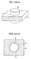
- Fig. 6a and Fig. 6b show a third embodiment of a bearing housing structure having the preform according to the present invention.
- the bearing housings are incorporated onto a cylinder block of an horizontally opposed four cylinder engine.
- the preform 1 integrally cast in the left and right bearing housings 23, 24 has a rectangular configuration and has a semicircular groove at one side of the rectangle.
- Other constructions are identical to those of Fig. 5a.
- Reference numerals 31, 32 denote a bearing metal accommodated in the left and right bearing housings 23, 24, respectively.
- the preform 1 since the preform 1 has a rectangular configuration, the preform 1 can have a larger MMC area than the preform 1 of Fig. 5a and as a result it provides a larger fatigue strength.
Landscapes
- Engineering & Computer Science (AREA)
- Mechanical Engineering (AREA)
- Chemical & Material Sciences (AREA)
- Composite Materials (AREA)
- Manufacturing & Machinery (AREA)
- Materials Engineering (AREA)
- General Engineering & Computer Science (AREA)
- Cylinder Crankcases Of Internal Combustion Engines (AREA)
- Manufacture Of Alloys Or Alloy Compounds (AREA)
Applications Claiming Priority (2)
| Application Number | Priority Date | Filing Date | Title |
|---|---|---|---|
| JP2002074216A JP2003268511A (ja) | 2002-03-18 | 2002-03-18 | 金属基複合材形成用プリフォーム及びその製造方法、並びにプリフォームを有するジャーナル構造 |
| JP2002074216 | 2002-03-18 |
Publications (1)
| Publication Number | Publication Date |
|---|---|
| EP1350857A1 true EP1350857A1 (de) | 2003-10-08 |
Family
ID=28035290
Family Applications (1)
| Application Number | Title | Priority Date | Filing Date |
|---|---|---|---|
| EP03251599A Withdrawn EP1350857A1 (de) | 2002-03-18 | 2003-03-15 | Vorkörperstruktur und Verfahren zur Herstellung eines Preforms aus Metall-Matrix-Verbundwerkstoff |
Country Status (3)
| Country | Link |
|---|---|
| US (2) | US20030180172A1 (de) |
| EP (1) | EP1350857A1 (de) |
| JP (1) | JP2003268511A (de) |
Cited By (1)
| Publication number | Priority date | Publication date | Assignee | Title |
|---|---|---|---|---|
| DE102009041395A1 (de) * | 2009-09-12 | 2011-03-24 | Volkswagen Ag | Lagerdeckel-Einlegeteil |
Families Citing this family (9)
| Publication number | Priority date | Publication date | Assignee | Title |
|---|---|---|---|---|
| JP4322062B2 (ja) * | 2003-07-23 | 2009-08-26 | 日本発條株式会社 | エンジンブロックおよびその製造方法 |
| EP1707301B1 (de) * | 2005-03-31 | 2008-06-18 | Siemens Aktiengesellschaft | Verfahren zum Aufbringen von Fasermatten auf die Oberfläche oder in eine Vertiefung eines Bauteiles |
| JP4498255B2 (ja) * | 2005-09-30 | 2010-07-07 | 富士重工業株式会社 | 金属基複合材形成用鉄系プリフォーム及び該鉄系プリフォームを有するジャーナル部構造 |
| JP2007100122A (ja) * | 2005-09-30 | 2007-04-19 | Fuji Heavy Ind Ltd | 金属基複合材形成用鉄系プリフォーム及びジャーナル部構造 |
| US7793703B2 (en) * | 2008-06-17 | 2010-09-14 | Century Inc. | Method of manufacturing a metal matrix composite |
| US20090309252A1 (en) * | 2008-06-17 | 2009-12-17 | Century, Inc. | Method of controlling evaporation of a fluid in an article |
| US9283734B2 (en) | 2010-05-28 | 2016-03-15 | Gunite Corporation | Manufacturing apparatus and method of forming a preform |
| EP3184831B1 (de) * | 2014-08-21 | 2018-04-04 | Nissan Motor Co., Ltd | Kurbelwellenlagerstruktur eines verbrennungsmotors |
| US10495141B2 (en) * | 2017-07-20 | 2019-12-03 | GM Global Technology Operations LLC | Bearing with lightweight backing substrate |
Citations (15)
| Publication number | Priority date | Publication date | Assignee | Title |
|---|---|---|---|---|
| JPS6187835A (ja) * | 1984-10-08 | 1986-05-06 | Honda Motor Co Ltd | 繊維強化金属材料の製造方法 |
| JPS61250132A (ja) * | 1985-04-26 | 1986-11-07 | Mazda Motor Corp | 複合部材の製造法 |
| JPS61250131A (ja) * | 1985-04-26 | 1986-11-07 | Mazda Motor Corp | 複合部材の製造法 |
| JPS61250133A (ja) * | 1985-04-26 | 1986-11-07 | Mazda Motor Corp | 複合部材の製造法 |
| JPS61257440A (ja) * | 1985-05-10 | 1986-11-14 | Toray Ind Inc | 繊維強化金属複合材料 |
| JPS61261046A (ja) * | 1985-05-15 | 1986-11-19 | 東レ株式会社 | 繊維強化金属複合材料 |
| JPS6270532A (ja) * | 1985-09-24 | 1987-04-01 | Nippon Denso Co Ltd | 繊維強化金属成形体 |
| JPS63303019A (ja) * | 1987-05-30 | 1988-12-09 | Toshiba Corp | 金属基複合材料用プリフォ−ムの製造方法 |
| JPH01242736A (ja) * | 1988-03-23 | 1989-09-27 | Suzuki Motor Co Ltd | 複合材用プリフォームの製造方法 |
| EP0363159A2 (de) * | 1988-10-05 | 1990-04-11 | Ford Motor Company Limited | Verfahren zur dimensionellen Stabilisierung einer Zwischenschicht zwischen Metallen ungleicher Art in einer Brennkraftmaschine |
| JPH0790416A (ja) * | 1993-09-13 | 1995-04-04 | Toyota Motor Corp | 金属基複合材料用成形体の製造方法 |
| JPH1192841A (ja) * | 1997-09-17 | 1999-04-06 | Mitsubishi Heavy Ind Ltd | 金属複合材製部品の製造方法 |
| US20020020287A1 (en) * | 2000-08-18 | 2002-02-21 | Suzuki Motor Corporation | Cylinder block and method of making the same |
| EP1229236A2 (de) * | 2001-01-31 | 2002-08-07 | Fuji Jukogyo Kabushiki Kaisha | Lagerungsgehause für einen Zylinderblock |
| US20030118260A1 (en) * | 2001-12-21 | 2003-06-26 | Suzuki Motor Corporation | Bearing cap structure for engine |
Family Cites Families (10)
| Publication number | Priority date | Publication date | Assignee | Title |
|---|---|---|---|---|
| GB1209916A (en) * | 1967-05-04 | 1970-10-21 | Nat Res Dev | Composite bearing materials and their manufacture |
| US3653882A (en) * | 1970-02-27 | 1972-04-04 | Nasa | Method of making fiber composites |
| US3679324A (en) * | 1970-12-04 | 1972-07-25 | United Aircraft Corp | Filament reinforced gas turbine blade |
| JPS5547335A (en) * | 1978-09-27 | 1980-04-03 | Sumitomo Chem Co Ltd | Manufacturing method of fiber reinforced metal based composite material |
| AU554140B2 (en) * | 1980-07-02 | 1986-08-07 | Dana Corporation | Thermally insulating coating on piston head |
| DE3343309C2 (de) * | 1983-11-30 | 1989-09-21 | Glyco-Metall-Werke Daelen & Loos Gmbh, 6200 Wiesbaden | Schichtverbundwerkstoff |
| GB8626226D0 (en) * | 1985-11-14 | 1986-12-03 | Ici Plc | Metal matrix composites |
| IT1228449B (it) * | 1989-02-22 | 1991-06-19 | Temav Spa | Procedimento per ottenere un legame metallurgico tra un materiale metallico o composito a matrice metallica e un getto di metallo o di lega metallica. |
| US5436042A (en) * | 1994-03-11 | 1995-07-25 | The Carborundum Company | Ceramic fiber-reinforced composite articles and their production |
| WO2001087520A1 (en) * | 2000-05-17 | 2001-11-22 | Saab Ab | Bearing reinforcement in light metal housing |
-
2002
- 2002-03-18 JP JP2002074216A patent/JP2003268511A/ja active Pending
-
2003
- 2003-03-15 EP EP03251599A patent/EP1350857A1/de not_active Withdrawn
- 2003-03-17 US US10/388,467 patent/US20030180172A1/en not_active Abandoned
-
2005
- 2005-10-14 US US11/249,384 patent/US20060046087A1/en not_active Abandoned
Patent Citations (15)
| Publication number | Priority date | Publication date | Assignee | Title |
|---|---|---|---|---|
| JPS6187835A (ja) * | 1984-10-08 | 1986-05-06 | Honda Motor Co Ltd | 繊維強化金属材料の製造方法 |
| JPS61250132A (ja) * | 1985-04-26 | 1986-11-07 | Mazda Motor Corp | 複合部材の製造法 |
| JPS61250131A (ja) * | 1985-04-26 | 1986-11-07 | Mazda Motor Corp | 複合部材の製造法 |
| JPS61250133A (ja) * | 1985-04-26 | 1986-11-07 | Mazda Motor Corp | 複合部材の製造法 |
| JPS61257440A (ja) * | 1985-05-10 | 1986-11-14 | Toray Ind Inc | 繊維強化金属複合材料 |
| JPS61261046A (ja) * | 1985-05-15 | 1986-11-19 | 東レ株式会社 | 繊維強化金属複合材料 |
| JPS6270532A (ja) * | 1985-09-24 | 1987-04-01 | Nippon Denso Co Ltd | 繊維強化金属成形体 |
| JPS63303019A (ja) * | 1987-05-30 | 1988-12-09 | Toshiba Corp | 金属基複合材料用プリフォ−ムの製造方法 |
| JPH01242736A (ja) * | 1988-03-23 | 1989-09-27 | Suzuki Motor Co Ltd | 複合材用プリフォームの製造方法 |
| EP0363159A2 (de) * | 1988-10-05 | 1990-04-11 | Ford Motor Company Limited | Verfahren zur dimensionellen Stabilisierung einer Zwischenschicht zwischen Metallen ungleicher Art in einer Brennkraftmaschine |
| JPH0790416A (ja) * | 1993-09-13 | 1995-04-04 | Toyota Motor Corp | 金属基複合材料用成形体の製造方法 |
| JPH1192841A (ja) * | 1997-09-17 | 1999-04-06 | Mitsubishi Heavy Ind Ltd | 金属複合材製部品の製造方法 |
| US20020020287A1 (en) * | 2000-08-18 | 2002-02-21 | Suzuki Motor Corporation | Cylinder block and method of making the same |
| EP1229236A2 (de) * | 2001-01-31 | 2002-08-07 | Fuji Jukogyo Kabushiki Kaisha | Lagerungsgehause für einen Zylinderblock |
| US20030118260A1 (en) * | 2001-12-21 | 2003-06-26 | Suzuki Motor Corporation | Bearing cap structure for engine |
Non-Patent Citations (9)
| Title |
|---|
| DATABASE WPI Section Ch Week 198701, Derwent World Patents Index; Class M26, AN 1987-002488, XP002248608 * |
| PATENT ABSTRACTS OF JAPAN vol. 010, no. 262 (C - 371) 6 September 1986 (1986-09-06) * |
| PATENT ABSTRACTS OF JAPAN vol. 011, no. 101 (C - 413) 31 March 1987 (1987-03-31) * |
| PATENT ABSTRACTS OF JAPAN vol. 011, no. 115 (C - 415) 10 April 1987 (1987-04-10) * |
| PATENT ABSTRACTS OF JAPAN vol. 011, no. 268 (C - 444) 29 August 1987 (1987-08-29) * |
| PATENT ABSTRACTS OF JAPAN vol. 013, no. 137 (C - 582) 5 April 1989 (1989-04-05) * |
| PATENT ABSTRACTS OF JAPAN vol. 013, no. 585 (C - 669) 22 December 1989 (1989-12-22) * |
| PATENT ABSTRACTS OF JAPAN vol. 1995, no. 07 31 August 1995 (1995-08-31) * |
| PATENT ABSTRACTS OF JAPAN vol. 1999, no. 09 30 July 1999 (1999-07-30) * |
Cited By (1)
| Publication number | Priority date | Publication date | Assignee | Title |
|---|---|---|---|---|
| DE102009041395A1 (de) * | 2009-09-12 | 2011-03-24 | Volkswagen Ag | Lagerdeckel-Einlegeteil |
Also Published As
| Publication number | Publication date |
|---|---|
| US20030180172A1 (en) | 2003-09-25 |
| US20060046087A1 (en) | 2006-03-02 |
| JP2003268511A (ja) | 2003-09-25 |
Similar Documents
| Publication | Publication Date | Title |
|---|---|---|
| EP0363159B1 (de) | Verfahren zur dimensionellen Stabilisierung einer Zwischenschicht zwischen Metallen ungleicher Art in einer Brennkraftmaschine | |
| EP1350857A1 (de) | Vorkörperstruktur und Verfahren zur Herstellung eines Preforms aus Metall-Matrix-Verbundwerkstoff | |
| US5654106A (en) | Sintered articles | |
| CN100591442C (zh) | 铁类预成型件 | |
| JPH0419345A (ja) | 内燃機関用のシリンダブロック、およびそれを製造する方法 | |
| JPH10265870A (ja) | アルミニウム基複合材料およびその製造方法 | |
| CA2332192C (en) | Oil pump | |
| US6814043B2 (en) | Structure of bearing housing of cylinder block | |
| JPH03229958A (ja) | 内燃機関用クランク軸受部 | |
| JP3705676B2 (ja) | 内燃機関用ピストンの製造方法 | |
| US20040074335A1 (en) | Powder metal connecting rod | |
| JP2000337348A (ja) | クランクシャフト用軸受 | |
| EP1652607B1 (de) | Verstärkungsglied, verfahren zur herstellung des verstärkungsglieds und motorblock | |
| CN1230614C (zh) | 内燃机的气缸体曲轴箱及其制造方法 | |
| US3744547A (en) | Methods of manufacturing crank-case envelopes for rotary piston internal combustion engines with sintered metal plug support | |
| CN111412082A (zh) | 带有加强构件的发动机壳体总成 | |
| EP0870919A1 (de) | Brennkraftmaschinenkolben und Verfahren zu seiner Herstellung | |
| US20070087217A1 (en) | Selectively reinforced powder metal components | |
| EP1580445A1 (de) | Kraftübertragungsbauteil aus Metallmatrixverbundwerkstoff | |
| JPH0610757A (ja) | セラミックライナを持つシリンダボディ及びその製造方法 | |
| JPH01186261A (ja) | バルブシートの接合方法 | |
| JPH08232755A (ja) | アルミ鋳造品 | |
| JPH01254366A (ja) | アルミニウム合金製ケーシングの製造方法及び同ケーシング製造用軸受部インサート | |
| JPH04263037A (ja) | エンジンおよび乗り物用の構造部材 | |
| US20040224143A1 (en) | Metal-ceramic composite material |
Legal Events
| Date | Code | Title | Description |
|---|---|---|---|
| PUAI | Public reference made under article 153(3) epc to a published international application that has entered the european phase |
Free format text: ORIGINAL CODE: 0009012 |
|
| AK | Designated contracting states |
Kind code of ref document: A1 Designated state(s): AT BE BG CH CY CZ DE DK EE ES FI FR GB GR HU IE IT LI LU MC NL PT RO SE SI SK TR |
|
| AX | Request for extension of the european patent |
Extension state: AL LT LV MK |
|
| 17P | Request for examination filed |
Effective date: 20040312 |
|
| AKX | Designation fees paid |
Designated state(s): DE |
|
| 17Q | First examination report despatched |
Effective date: 20040625 |
|
| RIN1 | Information on inventor provided before grant (corrected) |
Inventor name: SHIRAISHI, TOHRU Inventor name: KATSUYA, AKIHIRO Inventor name: ODA, TERUYUKI,C/O FUJI JUKOGYO KABUSHIKI KAISHA |
|
| RAP1 | Party data changed (applicant data changed or rights of an application transferred) |
Owner name: NHK SPRING CO., LTD. Owner name: FUJI JUKOGYO KABUSHIKI KAISHA |
|
| 17Q | First examination report despatched |
Effective date: 20040625 |
|
| RAP1 | Party data changed (applicant data changed or rights of an application transferred) |
Owner name: NHK SPRING CO., LTD. Owner name: FUJI JUKOGYO KABUSHIKI KAISHA |
|
| STAA | Information on the status of an ep patent application or granted ep patent |
Free format text: STATUS: THE APPLICATION IS DEEMED TO BE WITHDRAWN |
|
| 18D | Application deemed to be withdrawn |
Effective date: 20151001 |