EP1350578B1 - Machine de pliage des pièces en forme de barre et/ou tige, en particulier des tubes - Google Patents
Machine de pliage des pièces en forme de barre et/ou tige, en particulier des tubes Download PDFInfo
- Publication number
- EP1350578B1 EP1350578B1 EP20030005336 EP03005336A EP1350578B1 EP 1350578 B1 EP1350578 B1 EP 1350578B1 EP 20030005336 EP20030005336 EP 20030005336 EP 03005336 A EP03005336 A EP 03005336A EP 1350578 B1 EP1350578 B1 EP 1350578B1
- Authority
- EP
- European Patent Office
- Prior art keywords
- workpiece
- bending
- tool
- rotation axis
- pivot
- Prior art date
- Legal status (The legal status is an assumption and is not a legal conclusion. Google has not performed a legal analysis and makes no representation as to the accuracy of the status listed.)
- Expired - Lifetime
Links
Images


Classifications
-
- B—PERFORMING OPERATIONS; TRANSPORTING
- B21—MECHANICAL METAL-WORKING WITHOUT ESSENTIALLY REMOVING MATERIAL; PUNCHING METAL
- B21D—WORKING OR PROCESSING OF SHEET METAL OR METAL TUBES, RODS OR PROFILES WITHOUT ESSENTIALLY REMOVING MATERIAL; PUNCHING METAL
- B21D7/00—Bending rods, profiles, or tubes
- B21D7/02—Bending rods, profiles, or tubes over a stationary forming member; by use of a swinging forming member or abutment
- B21D7/024—Bending rods, profiles, or tubes over a stationary forming member; by use of a swinging forming member or abutment by a swinging forming member
-
- B—PERFORMING OPERATIONS; TRANSPORTING
- B21—MECHANICAL METAL-WORKING WITHOUT ESSENTIALLY REMOVING MATERIAL; PUNCHING METAL
- B21D—WORKING OR PROCESSING OF SHEET METAL OR METAL TUBES, RODS OR PROFILES WITHOUT ESSENTIALLY REMOVING MATERIAL; PUNCHING METAL
- B21D7/00—Bending rods, profiles, or tubes
- B21D7/12—Bending rods, profiles, or tubes with programme control
Definitions
- the invention relates to a bending machine for bending rod-like and / or rod-like workpieces, in particular of pipes, with a machine base on which a holder for a workpiece and a tool unit are provided with at least one bending tool, wherein the bending tool under relative movement of tool parts in Workpiece transverse direction can be opened and closed and forms at least one workpiece holder and wherein the tool unit is movable relative to the machine base body by the tool unit on a pivoting carrier relative to this movable and the pivot carrier is rotatably mounted on the machine base body about a running in the workpiece longitudinal direction pivot carrier axis of rotation.
- the tool unit On such bending machines, the tool unit is to be moved relative to the machine base body or to the workpiece held thereon for various reasons.
- tool units which have a plurality of superimposed bending tools for Mehrrotebiegen, relative to the machine base body such a procedure that the particular bending tool to be used can attack on the workpiece to be deformed.
- Tool units for bidirectional bending which have at least one bending tool for each bending direction, are positioned relative to the machine base body or the workpiece held thereon such that in each case the bending tool can be used for the desired bending direction.
- tool units are also used for workpiece handling and moved relative to the machine body for this purpose.
- a generic bending machine of the latter type is known from EP-0 872 292 B1.
- the pivot support for the tool unit is formed by a plate which is rotatably mounted on a machine base frame about an axis extending in the workpiece longitudinal direction axis.
- the tool unit is guided linearly by means of a carriage perpendicular to the plate rotation axis.
- the previously known tool unit can be moved before or after the workpiece machining in positions in which they take with the tool parts of a bending tool to be machined workpieces from a loading magazine or in which they processed by means of the tool parts of the bending tool workpieces to a Unloading station can pass.
- the different positions of the tool unit or of the workpiece holder formed by its bending tool can be realized in each case only with a single rotational position of the plate of the tool unit linearly leading plate relative to the machine base frame.
- a powerful traversing drive is provided for linear movement of the carriage on the plate.
- the linear guide for the carriage builds at corresponding travel lengths of the carriage relatively large.
- the present invention has set itself the goal.
- both the tool unit is rotatably mounted on the pivot carrier and the pivot support on the machine body.
- the tool axis of rotation and the pivot carrier axis of rotation are rectified. Due to the inventive features can be different positions of the tool unit according to the invention bending machines and to realize different positions of the workpiece holder or workpiece holders on the tool unit respectively with different rotational positions of the tool unit relative to the pivot carrier or the pivot carrier relative to the machine base body.
- machine tools according to the invention are distinguished by great flexibility with respect to the movements to be performed by the tool unit in different functional sequences with respect to the machine main body and with respect to the alignment of the tool unit and the pivot carrier relative to the machine base body or to the workpiece to be machined or machined.
- the arrangement of the pivot carrier can be matched to the arrangement of the workpiece so that collisions with the workpiece are excluded. If the tool unit is "balanced" in relation to the tool axis of rotation, small-sized drives of low power, in particular small-sized electric drives, are sufficient for the rotational movement of the tool unit.
- the leadership of the tool unit in its rotational movement can be accomplished with structurally simple and space-saving means to be accommodated.
- the bending tools of the tool units can be of different types. For example, bending tools for rolling bending and / or bending tools for roll bending are conceivable.
- a swivel carrier is used in the case of Erfindungsbauart according to claim 2, which ensures the required range of the tool unit mounted thereon, with appropriate design regardless of its structurally simple design.
- a pivoting arm is characterized by a relatively small mass and by a relatively small volume of construction. The machine base body is only partially covered by the swivel arm.
- the "principle of the two axes of rotation" according to the invention is implemented to realize various machine functions.
- the rotational mobility of the tool unit relative to the pivot carrier and the rotational mobility of the pivot carrier relative to the machine base body used to selectively transfer bending tools different tool levels in a bending-functional position.
- the pivot bearing of the tool unit and the pivot carrier serves to bring in the direction of rotation of the tool unit about the tool rotation axis successive bending tools optionally in a position in which they can deform the workpiece in question bending.
- Claim 5 relates to an embodiment of the bending machine according to the invention, with which workpieces without external tool change can be selectively bent in different directions.
- the tool unit is used to take over workpieces to be machined and / or for the transfer of machined workpieces.
- the pivot carrier and tool unit By appropriate rotational movement of the pivot carrier and tool unit, the latter can be moved into a workpiece receiving position and after taking over a workpiece to be machined in a bending functional position, when taking the workpiece taken over by the tool unit workpiece can be fixed to the machine base body-side workpiece holder. After one or more subsequent bending operations, the machined workpiece can be unloaded by moving the tool unit into a workpiece transfer position from the bending machine.
- claim 8 is provided in a preferred embodiment of the invention that the reorientation of the workpiece storage coupled reorientation of the workpiece an additional reorientation is superimposed. Due to this superimposition, orientation requirements of a subsequent workpiece machining can be taken into account simultaneously with the mutually coupled reorientations of workpiece and workpiece storage. In this way, the workpiece machining can be optimized in time.
- a bending machine in the form of a tube bending machine 1 has a machine base body 2, on which various functional units are provided. At its top of the machine base body 2 carries a workpiece feed device 3 with a guide rails 4 of the machine body 2 along movable feed carriage 5. This has as a holder for machined workpieces a controlled open- and closable and also rotatable about its axis collet 6. Also mounted on the machine base body 2 is a mandrel drive 7, from which a mandrel rod 8 protrudes. At the front end of the mandrel bar 8, a mandrel not shown in detail is attached in a conventional manner. In the example case shown in FIG. 1, the mandrel drive 7 is attached to a rear arm 9 of the machine main body 2.
- pivot support 10 which is formed in the example shown as an angled pivoting arm.
- the pivot carrier 10 is rotatable relative to the machine base body 2 about a pivot carrier axis of rotation 11.
- the pivot carrier pivot axis 11 extends in a workpiece longitudinal direction 12, which is indicated by dash-dotted lines in FIG.
- a tool unit 15 is mounted on an axis-parallel pivot carrier leg 14.
- the tool unit 15 is mounted rotatably about a tool rotation axis 16 on the pivot carrier 10.
- the tool axis of rotation 16 extends in the workpiece longitudinal direction 12 and thus parallel to the pivot carrier axis of rotation 11. Of the latter, the tool axis of rotation 16 is radially spaced.
- Part of the tool unit 15 are bending tools not shown in detail in FIG. 1, which are mounted on a tool carrier 17 of the tool unit 15 and are arranged at a radial distance from the tool rotation axis 16.
- a programmable computer control 18 shown in Fig. 1 suggestively all movements on the pipe bending machine 1 are effected by means of motor, in particular electric motor drives.
- the bending tools used on the tube bending machine 1 are of conventional design.
- a tool unit 15a as described in detail in FIGS. 2 to 13 can be removed, has a single bending tool 20 for pipe processing.
- This comprises as a tool part a conventional bending mold 21 which is rotatably mounted on a tool carrier 17a of the tool unit 15a about a bending axis 22. Over a part of its outer circumference, the bending mold 21 is provided with a pipe groove 23, whose cross section is matched to the cross section of workpieces to be bent in the form of tubes 24.
- a pressure element in the form of a clamping jaw 25.
- This likewise has a pipe groove, namely a pipe groove 26, adapted to the cross section of the pipes 24.
- the jaw 25 moves in the direction of a double arrow 27 relative to the bending mold 21 and thereby the bending tool 20 are opened and closed.
- the clamping jaw 25 is pivotable about the bending axis 22 with a pivoting arm 28 of the tool carrier 17a.
- the tool unit 15a or the bending tool 20 can also be used to bend the tubes 24 and also to handle them.
- a tube 24 is singulated at a loading magazine 29.
- the isolated tube 24 rests against a machine-side stop angle 30 of the loading magazine 29, which extends perpendicularly to the plane of the drawing of FIG. 2 only over a short distance of the tube 24. Adjacent to the stop angle 30, the tube 24 is exposed.
- the tool unit 15 a is arranged with the open bending tool 20.
- the pivot carrier 10 is rotated about the pivot axis 11, the tool unit 15a about the tool axis of rotation 16 accordingly.
- the tool unit 15a is rotated clockwise around the tool rotation axis 16 until the singulated pipe 24 comes to rest in the pipe groove 23 of the bending mold 21 (FIG. 3). Subsequently, the bending tool 20 is closed by moving the jaw 25. The tube 24 is now arranged in the interior of the workpiece holder formed by the tube grooves 23, 26 and fixed there in a clamping manner (FIG. 4).
- the tool unit 15a is transferred with the tube 24 held thereon by rotating about the tool axis of rotation 16 and rotating the pivot carrier 10 about the pivot carrier axis 11 in a position opposite to the pipe 24 with its machine-side end of the open collet 6 of the workpiece feed device 3 , In an intermediate position, the tube 24 in Fig. 5, in its end position in Fig. 6 is shown.
- the pivot carrier 10 is inclined in the illustration to the right, the tool unit 15a is tilted counterclockwise.
- the arrangement of the tool unit 15a and the pivot carrier 10 shown in FIG. 7 is possible.
- the position occupied by the tube 24 according to FIG. 7 is identical to the position according to FIG. 6.
- One and the same position of the tube 24 or the workpiece holder formed by the tube grooves 23, 26 can accordingly be approached with different kinematics.
- the tool unit 15a and the Swivel beams 10 may be arranged differently at one and the same position of the tube 24.
- the arrangement of the tool unit 15a and the pivot support 10 can be adjusted to the course of the pipe 24 at the front end of the pipe bending machine 1. If the tube 24 is bent during its processing, for example, to the machine base body 2, so about the pivot support 10 can be aligned such that a collision between it and the tube 24 is avoided.
- the "interference contour" formed by the tool unit 15a and / or the pivoting carrier 10 can be arranged in such a way that the tube 24 comes to rest outside of this interference contour and thus obstructs the workpiece machining.
- the feed slide 5 moves the workpiece feed device 3 computer-controlled so far to the tube 24 until its machine-side end is arranged inside the open collet 6. Subsequently, the collet 6 is also closed by computer control and the tube 24 is fixed with its machine-side end to the workpiece feed device 3. It now close in a conventional manner several bending operations. In each bending operation, the pivot arm 28 is pivoted with the jaw 25 about the bending axis 22 and at the same time the bending mold 21 is rotated about the bending axis 22. The clamped between the bending mold 21 and jaw 25 tube 24 is thereby taken and deformed.
- the bending tool 20 is opened and the tube 24 is adjusted by means of the workpiece feed device 3 in the workpiece longitudinal direction 12. With the replacement in the workpiece longitudinal direction 12, the tube 24 is rotated if necessary by controlled rotation of the collet 6 to the workpiece longitudinal direction 12. After completion of the processing, the tube 24 has the shape shown in Fig. 8.
- the tool unit 15a can be transferred with the tube 24 held thereon with rotation about the tool axis of rotation 16 and with rotation of the pivot carrier 10 about the pivot carrier pivot axis 11 in a workpiece transfer position, as shown in Figs. 11 and 12 is illustrated.
- Previously occupied intermediate positions of the tool unit 15a are shown in FIGS. 9 and 10 can be seen.
- the tube 24 is arranged on a workpiece deposit 31 of an unloading station 32 while the bending tool 20 is still closed.
- the tool unit 15a can be removed from the deposited tube 24 by rotating again about the tool rotation axis 16 and again turning the pivot carrier 10 about the pivot carrier rotation axis 11 (FIG. 13) and then again into the position according to FIG Fig. 2 are moved. It may then follow another cycle of the kind described.
- the tool unit 15b is designed as a multi-level unit and, as such, provided with two bending tools 40, 60 arranged one above the other under the definition of different tool planes.
- the bending tool 40 comprises as tool parts a bending mold 41 and an associated clamping jaw 45, the bending tool 60 a bending mold 61 and a clamping jaw 65.
- the bending molds 41, 61 are rotatable about a common bending axis 42, the clamping jaws 45, 65 are together with a pivot arm 48 of a tool carrier 17b about the bending axis 42 pivotally.
- the clamping jaws 45, 65 are displaceable on the pivot arm 48 in the direction of a double arrow 47.
- bends can be produced with different bending radii.
- FIG. 14 shows the tool unit 15b in a machine operating phase in which the bending tool 40 assumes a bending functional position on the tube 24.
- the tube 24 is held clamped in a workpiece holder, which is formed by a tube groove 43 of the bending mold 41 and a tube groove 46 of the clamping jaw 45.
- a workpiece holder which is formed by a tube groove 43 of the bending mold 41 and a tube groove 46 of the clamping jaw 45.
- Another workpiece holder is formed on the tool unit 15b by a tube groove 63 of the bending mold 61 and a tube groove 66 of the clamping jaw 65. In the operating state illustrated in FIG. 14, the workpiece holder 63, 66 is unused.
- the bending tool 40 is to be opened (FIG. 15).
- the bending tool 60 is thus inevitably mitgesöff.
- the bending tool 60 is transferred into a bending-functional position by rotation of the tool unit 15b about the tool axis of rotation 16 and rotation of the pivot carrier 10 about the pivot carrier axis of rotation 11.
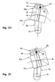
- the bending functional position of the meanwhile closed bending tool 60 is shown in FIG.
- Prior to this operating state intermediate positions of the tool unit 15b are shown in FIGS. 16 to 19 can be seen.
- the tool unit 15b is tilted about the tool rotation axis 16 in the clockwise direction, the pivot carrier 10 is pivoted counterclockwise against the vertical.
- a corresponding bending functional position of the bending tool 60 can be achieved with the alignment of tool unit 15b and pivoting carrier 10 shown in FIG.
- the position of the workpiece holder 63, 66 according to FIG. 20 coincides identically with the position assumed by the tool holder 63, 66 in FIG. 21.
- the swivel arm 48 of the tool carrier 17b is pivoted about the bending axis 42 while rotating the bending molds 41, 61, a bend results on the pipe 24 whose bending radius exceeds the bending radius of the previously Bending created by the bending tool 40 exceeds.
- FIGS. 22 to 30 A tool unit 15c, by means of which pipes 24 can be bent in two opposite directions without external tool change, is shown in FIGS. 22 to 30 shown.
- a tool carrier 17c of the tool unit 15c two bending tools 80, 100 are provided on both sides of the tool rotation axis 16. Bending molds 81, 101 of the bending tools 80, 100 are seated on a common bending axis 82.
- About the bending axis 82 is pivotable about a pivot arm 88 on opposite sides of a jaw 85 of the bending tool 80 and a jaw 105 of the bending tool 100 stores.
- the jaw 85 is movable in the direction of a double arrow 87 opposite the bending mold 81, the clamping jaw 105 in the direction of a double arrow 107 relative to the bending mold 101.
- Pipe grooves 83, 86 on the bending mold 81 and the clamping jaw 85 and pipe grooves 103, 106 on the bending mold 101 and the jaw 105 form workpiece holders, in which the tube 24 can be fixed.
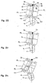
- FIG. 22 shows the tool unit 15c in an operating phase in which the bending tool 80 assumes a bending functional position.
- the bending tool 100 is to be transferred into a bending-functional position.
- the bending tool 80 is initially opened for this purpose (FIG. 23).
- the tool unit 15c is pivoted about the tool rotation axis 16 and the pivot support 10 about the pivot support axis 11 matched to each other until the tube 24 in the tube groove 103 of the bending mold 101 of the bending tool 100 comes to rest (FIGS.
- the bending tool 100 is closed by moving the clamping jaw 105.
- a corresponding bending functional position is assumed by the bending tool 100 according to FIG. With respect to FIG. 29, the alignment of the tool unit 15 c and the orientation of the pivot carrier 10 are changed.
- the swivel arm 88 is pivoted about the bending axis 82 while the bending mold 81 is rotated, a left-hand bend results on the pipe 24.
- the tool unit 15c may also be used for workpiece handling, i. for the adoption of pipes to be machined 24 and for the transfer of processed pipes 24 are used. Accordingly, the tool unit 15b according to FIGS. Use 14 to 21 in addition to the Multi-Level Turn function. Also, tool units with bending tools arranged on both sides of the tool rotation axis are conceivable, wherein a plurality of bending tools are arranged one above the other on at least one side of the tool rotation axis and thus form different tool planes. In this case, one and the same tool unit allows workpiece handling, multi-level bending and right-left bending.
- the functional alignment of the tubes 24 to the workpiece longitudinal direction 12 assumes in all machining operations a workpiece rotary drive with the means of computer control 18 in addition to the tool parts described in detail include the bending tools 20, 40, 60, 80, 100 all other common components such as slides and / or Faltenglätter.
- the mandrel 8 of the pipe bending machine 1 is used in the workpiece machining in the usual way.
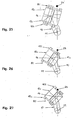
- FIGS. 31 to 34 show highly schematic constructional relationships which essentially correspond to those according to FIGS. 14 to 21.
- a tool unit 15d is designed as a multi-level bending unit and as such provided with two bending tools 40a, 60a in the form of superimposed conventional rotary bending tools.
- the bending tools 40a, 60a, FIGS. 31 to 34 for the sake of clarity, only bending molds 41a, 61a are shown.
- Pipe grooves 43a, 63a of the bending molds 41a, 61a like a pipe 24a to be machined as a workpiece, have a rectangular cross-section.
- the tool unit 15d is pivoted about the tool rotation axis 16 to the pivot carrier 10.
- This is rotatably mounted about the pivot support axis 11 on the machine base body, not shown, of the respective pipe bending machine.
- the pivot carrier 10 can be moved about the pivot axis 11 and the tool unit 15d about the tool axis of rotation 16.
- the tube 24a is fixed with its machine-side end in the collet of the pipe bending machine.
- the collet is rotatable as usual by means of a workpiece rotary drive.
- Connected to the rotation of the collet is a rotational movement of the tube 24a held by means of the collet about a plane perpendicular to the plane of the drawing. 31 to 34 extending workpiece axis of rotation 67. All movements are controlled by the programmable computer control of the pipe bending machine and are in a corresponding manner also in the case of the devices according to FIGS. 1 to 30 possible.
- Fig. 31 shows the overall arrangement in an operation state in which a previous processing of the pipe 24a is completed and a second pipe processing is to be performed by means of the upper bending tool 40a of the tool unit 15d.
- the bending tool 40a is opened and the bending mold 41a is moved close to the pipe 24a with coordinated pivoting movements of the tool carrier 17d about the tool rotation axis 16 and of the pivoting carrier 10 about the pivot carrier rotation axis 11.
- the orientation of the tube 24a about the workpiece axis of rotation 67 is to be changed in accordance with the reorientation of the tube groove 43a.
- the reorientation of the tube 24a is forcibly coupled via the computer control of the tube bending machine with the reorientation of the tube groove 43a, ie the reorientation of the tube 24a takes place to the same extent as the reorientation of the tube groove 43a.
- Fig. 34 shows the conditions which, when dispensing with the according to Figs. 31 to 33 intended reorientation of the tube 24 a would result. It is not difficult to see that the pipe 24a would tilt without reorientation about the workpiece axis of rotation 67 in the pipe groove 43a of the bending mold 41a. The transfer of the tube 24a in its processing position in the tube groove 43a would thus at least difficult. A corresponding complication would result in deviating from the rectangular shape shown cross-sectional geometries to be machined workpieces.
- the pipe 24a assumes its machining position in the pipe groove 43a.
- the tube groove 43a forms a workpiece support.
- the overall arrangement is in the state of readiness for processing.
- the tube 24a and the tube groove 43a are each arranged with a desired orientation about the workpiece axis of rotation 67. Accordingly, the tube 24a is aligned about the workpiece axis of rotation 67 such that in the subsequent tube machining results in a bend with the desired course of the bending plane.
- the bending tool 40a of the tool unit 15d is to be closed by corresponding movement of the associated clamping jaw. Thereafter, a not shown in detail and provided with the jaws of the tool unit 15 d pivot arm about a bending axis 42 a pivoted and at the same time the bending mold 41 a are rotated about the bending axis 42 a.
- a result of machining results in a bend of the tube 24a with a perpendicular to the bending axis 42a extending and in Fig. 33 dash-dotted lines indicated bending plane.
- the bending tool 40a is to be opened and the pipe 24a is to be removed from the pipe groove 43a by moving the pipe groove 43a or the bending mold 41a in the pipe transverse direction.
- the operating state according to FIG Accordingly, even when removing the tube 24a from the processing position in the tube groove 43a, the orientation of the tube 24a about the workpiece rotational axis 67 and the corresponding orientation of the tube groove 43a are changed.
- the reorientation of the tube 24a takes place to the same extent as the reorientation of the tube groove 43a. Both reorientations are coupled with one another in terms of control technology.
- This forced coupling ends at the earliest, as soon as the tube 24a and the bending mold 41a come out of contact. After completion of the forced coupling, the orientations of pipe 24a and pipe groove 43a may also be changed unevenly.
- the pipe 24a is initially moved by moving the collet 6 to the viewer of FIGS. 31 to 34 to advance before then the in Figs. 31 to 33 outlined movements have to be executed again.
- the additional reorientation leading to a displacement of the bending plane is superimposed by means of the workpiece rotary drive controlled by the programmable computer controller. If the bending mold 41a or the pipe groove 43a is subsequently moved again against the pipe 24a, then the bending mold 41a or the pipe groove 43a already finds the pipe 24a with the orientation from which the pipe 24a has the desired orientation after being transferred to the machining position ie that orientation, which is assigned to the now desired course of the bending plane.
- a reorientation of the pipe 24a in addition to the reorientation positively coupled with the reorientation of the pipe groove 43a is also required in principle if after machining of the tube 24a by means of one of the bending tools 40a, 60a of the tool unit 15d a processing by means of the respective other bending tool 40a, 60a is performed. This is true in any case when the position of the bending plane of the preceding coincides with the position of the bending plane of the subsequent bend.
- Reorientations of the type described may also be advisable when using tool units that differ in their construction from the tool unit 15d and, for example, the tool units 15a according to FIGS. 2 to 13 and 15c according to FIGS. 22 to 30 correspond.
- Workpiece bearings are in each case formed by the tube grooves 23, 43, 63, 83, 103 of the bending molds 21, 41, 61, 81, 101.
- the bending tools 40a, 60a of the tool unit 15d workpieces to be machined can also be taken over in a workpiece receiving position or deposited in a workpiece transfer position.
Landscapes
- Engineering & Computer Science (AREA)
- Mechanical Engineering (AREA)
- Bending Of Plates, Rods, And Pipes (AREA)
Claims (9)
- Machine à cintrer des pièces en forme de barre et/ou de tige, notamment des tubes ou tuyaux (24, 24a), comprenant un corps de base de machine (2) sur lequel sont prévus un dispositif de fixation (6) pour une pièce à usiner, ainsi qu'une unité d'outils (15, 15a, 15b, 15c, 15d) munie d'au moins un outil de cintrage (20 ; 40, 60 ; 80, 100, 40a, 60a), l'outil de cintrage (20 ; 40, 60 ; 80, 100, 40a, 60a) pouvant s'ouvrir et se fermer dans la direction transversale de la pièce à usiner en déplaçant des parties ou pièces d'outil (21, 25 ; 41, 45 ; 61, 65 ; 81, 85 ; 101, 105) l'une par rapport à l'autre et formant au moins un réceptacle de pièce à usiner (23, 26 ; 43, 46 ; 63, 66 ; 83, 86 ; 103, 106), et l'unité d'outils (15, 15a, 15b, 15c, 15d) étant mobile par rapport au corps de base de machine (2), dans la mesure où l'unité d'outils (15, 15a, 15b, 15c, 15d) est montée sur un support pivotant (10) de façon à être mobile par rapport à celui-ci et où le support pivotant (10) est monté sur le corps de base de machine (2) de façon à tourner autour d'un axe de rotation (11) de support pivotant s'étendant dans la direction longitudinale (12) de la pièce à usiner, caractérisée en ce que, dans le cadre ou pendant l'usinage d'une pièce, pour positionner l'unité d'outils (15, 15a, 15b, 15c, 15d) sur la pièce à usiner dans la direction transversale de la pièce à usiner, ladite unité d'outils n'est mobile par rapport au corps de base de machine (2) exclusivement pour effectuer un mouvement de rotation autour de l'axe de rotation (11) de support pivotant et un mouvement de rotation autour de l'axe de rotation (16) de l'outil, l'unité d'outils (15, 15a, 15b, 15c, 15d) étant montée sur le support pivotant (10) de manière à pouvoir tourner autour de l'axe de rotation (16) de l'outil qui s'étend dans la direction longitudinale (12) de la pièce à usiner, et l'axe de rotation (11) du support pivotant et l'axe de rotation (16) de l'outil, ainsi que l'axe de rotation (16) de l'outil et le réceptacle de pièce à usiner (23, 26 ; 43, 46 ; 63, 66 ; 83, 86 ; 103, 106) étant disposés de façon décalée les uns par rapport aux autres.
- Machine à cintrer selon la revendication 1, caractérisée en ce que le support pivotant (10) est réalisé en tant que bras pivotant.
- Machine à cintrer selon l'une des revendications précédentes, caractérisée en ce que l'unité d'outils (15b, 15d) comprend plusieurs outils de cintrage (40, 60 ; 40a, 60a) qui présentent chacun, en tant que parties ou pièces d'outil, un moule de cintrage (41, 61 ; 41a, 61a) ainsi qu'un élément presseur (45, 65) associé à ce dernier, les moules de cintrage (41, 61 ; 41a, 61a) de différents outils de cintrage (40, 60 ; 40a, 60a) étant disposés de manière superposée en définissant différents plans d'outil, et différents outils de cintrage (40, 60 ; 40a, 60a) pouvant être sélectivement mis dans une position fonctionnelle de cintrage en faisant tourner l'unité d'outils (15b,15d) autour de l'axe de rotation (16) des outils et le support pivotant (10) autour de l'axe de rotation (11) du support pivotant.
- Machine à cintrer selon l'une des revendications précédentes, caractérisée en ce que l'unité d'outils (15c) comprend plusieurs outils de cintrage (80, 100) se suivant dans le sens de rotation de l'unité d'outils (15c) autour de l'axe de rotation (16) des outils, la rotation de l'unité d'outils (15c) autour de l'axe de rotation (16) des outils et la rotation du support pivotant (10) autour de l'axe de rotation (11) du support pivotant permettant de mettre sélectivement différents outils de cintrage (80, 100) dans une position fonctionnelle de cintrage.
- Machine à cintrer selon l'une des revendications précédentes, caractérisée en ce que l'unité d'outils (15c) comprend plusieurs outils de cintrage (80, 100) qui présentent chacun en tant que parties ou pièces d'outil un moule de cintrage (81, 101) et une mâchoire de serrage (85, 105) associée à ce dernier, les moules de cintrage (81, 101) étant disposés le long d'un axe de cintrage (82) s'étendant dans la direction transversale de la pièce à usiner, de part et d'autre de l'axe de rotation (16) des outils, et, pour cintrer une pièce, les moules de cintrage (81, 101) et la ou les mâchoires de serrage (85, 105) pouvant respectivement tourner et pivoter autour de l'axe de cintrage (82), tandis que la pièce à usiner est immobilisée dans le réceptacle de pièce à usiner (83, 86 ; 103, 106), et la rotation de l'unité d'outils (15c) autour de l'axe de rotation (16) des outils et la rotation du support pivotant (10) autour de l'axe de rotation (11) du support pivotant permettant de mettre sélectivement dans une position fonctionnelle de cintrage des outils de cintrage (80, 100) disposés de part et d'autre de l'axe de rotation (16) des outils.
- Machine à cintrer selon l'une des revendications précédentes, caractérisée en ce que la rotation de l'unité d'outils (15, 15a, 15b, 15c, 15d) autour de l'axe de rotation (16) des outils et la rotation du support pivotant (10) autour de l'axe de rotation (11) du support pivotant permettent de déplacer un outil de cintrage (20 ; 40, 60 ; 80, 100 ; 40a, 60a) dans une position de réception de la pièce à usiner, afin de prendre en charge une pièce à usiner et/ou dans une position de transfert de la pièce à usiner, afin de transférer une pièce usinée.
- Machine à cintrer selon l'une des revendications précédentes, caractérisée en ce que sont prévus un entraînement en pivotement de l'outil pour faire tourner le support pivotant (10) autour de l'axe de rotation (11) du support pivotant et/ou pour faire tourner l'unité d'outils (15, 15a, 15b, 15c, 15d) équipée d'au moins un outil de cintrage (20 ; 40, 60 ; 80, 100 ; 40a, 60a) autour de l'axe de rotation (16) des outils, un entraînement en rotation de la pièce à usiner pour faire tourner la pièce à usiner (24, 24a) immobilisée dans le dispositif de fixation (6) autour d'un axe de rotation (67) de pièce à usiner s'étendant dans la direction longitudinale de la pièce à usiner, ainsi qu'une commande d'entraînement destinée à commander l'entraînement en pivotement de l'outil et l'entraînement en rotation de la pièce à usiner, en ce que la pièce à usiner (24, 24a) dans une position d'usinage dans un support de pièce à usiner associé (23 ; 43, 63 ; 83, 103 ; 43a, 63a) d'un outil de cintrage (20 ; 40, 60 ; 80, 100 ; 40a, 60a) et le support de pièce à usiner associé (23 ; 43, 63 ; 83, 103 ; 43a, 63a) présentent, lorsqu'ils sont prêts pour l'usinage, une orientation théorique ou de consigne autour de l'axe de rotation (67) de la pièce à usiner, et en ce qu'en commandant l'entraînement en rotation de la pièce à usiner et l'entraînement en pivotement de l'outil à l'aide de la commande d'entraînement, la pièce à usiner (24, 24a) et le support de pièce à usiner associé (23 ; 43, 63 ; 83, 103 ; 43a, 63a) peuvent changer d'orientation de façon coordonnée par rapport à leur orientation théorique ou de consigne respective à l'occasion du déplacement du support de pièce à usiner associé (23 ; 43, 63 ; 83, 103 ; 43a, 63a) destiné à mettre la pièce à usiner (24, 24a) dans la position d'usinage sur le support de pièce à usiner associé (23 ; 43, 63 ; 83, 103 ; 43a, 63a) et/ou lors du déplacement du support de pièce à usiner associé (23 ; 43, 63 ; 83, 103 ; 43a, 63a) destiné à libérer ou enlever la pièce à usiner, (24, 24a) de la position d'usinage sur le support de pièce à usiner associé (23 ; 43, 63 ; 83, 103 ; 43a, 63a), l'orientation de la pièce à usiner (24, 24a) pouvant être modifiée dans la même mesure que celle du support de pièce à usiner (23 ; 43, 63 ; 83, 103 ; 43a, 63a).
- Machine à cintrer selon l'une des revendications précédentes, caractérisée en ce que, lors du déplacement destiné à mettre la pièce à usiner (24, 24a) dans la position d'usinage sur le support de pièce à usiner associé (23 ; 43, 63 ; 83, 103 ; 43a, 63a), et/ou lors du déplacement destiné à libérer la pièce à usiner (24, 24a) de la position d'usinage sur le support de pièce à usiner associé (23 ; 43, 63 ; 83, 103 ; 43a, 63a), le support de pièce à usiner associé (23 ; 43, 63 ; 83, 103 ; 43a, 63a) peut être déplacé par rapport à la pièce à usiner (24, 24a) par l'entraînement en pivotement de l'outil, ainsi que par l'entraînement en rotation de la pièce à usiner, dans une phase de déplacement dans laquelle la pièce à usiner (24, 24a) et le support de pièce à usiner associé (23 ; 43, 63 ; 83, 103 ; 43a, 63a) ne se touchent pas et dans laquelle un changement d'orientation supplémentaire peut être superposé au changement d'orientation de la pièce à usiner (24, 24a) coordonné au changement d'orientation du support de pièce à usiner associé (23 ; 43, 63 ; 83, 103 ; 43a, 63a), lequel changement d'orientation supplémentaire est réalisé au moyen de l'entraînement en rotation de la pièce à usiner commandé par la commande d'entraînement.
- Machine à cintrer selon l'une des revendications précédentes, caractérisée par une commande d'entraînement se présentant sous la forme d'une commande programmable par ordinateur (18).
Priority Applications (1)
| Application Number | Priority Date | Filing Date | Title |
|---|---|---|---|
| EP20030005336 EP1350578B1 (fr) | 2002-04-03 | 2003-03-12 | Machine de pliage des pièces en forme de barre et/ou tige, en particulier des tubes |
Applications Claiming Priority (3)
| Application Number | Priority Date | Filing Date | Title |
|---|---|---|---|
| EP02007294A EP1350577A1 (fr) | 2002-04-03 | 2002-04-03 | Machine de pliage des pièces en forme de barre ou tige, en particulier des tubes |
| EP02007294 | 2002-04-03 | ||
| EP20030005336 EP1350578B1 (fr) | 2002-04-03 | 2003-03-12 | Machine de pliage des pièces en forme de barre et/ou tige, en particulier des tubes |
Publications (2)
| Publication Number | Publication Date |
|---|---|
| EP1350578A1 EP1350578A1 (fr) | 2003-10-08 |
| EP1350578B1 true EP1350578B1 (fr) | 2007-04-25 |
Family
ID=28043258
Family Applications (1)
| Application Number | Title | Priority Date | Filing Date |
|---|---|---|---|
| EP20030005336 Expired - Lifetime EP1350578B1 (fr) | 2002-04-03 | 2003-03-12 | Machine de pliage des pièces en forme de barre et/ou tige, en particulier des tubes |
Country Status (1)
| Country | Link |
|---|---|
| EP (1) | EP1350578B1 (fr) |
Cited By (1)
| Publication number | Priority date | Publication date | Assignee | Title |
|---|---|---|---|---|
| DE102018128903A1 (de) | 2018-11-16 | 2020-05-20 | Wafios Aktiengesellschaft | Vorrichtung zum Biegen stabförmiger Werkstücke |
Families Citing this family (3)
| Publication number | Priority date | Publication date | Assignee | Title |
|---|---|---|---|---|
| DE102013200850B4 (de) | 2013-01-21 | 2015-01-22 | Wafios Aktiengesellschaft | Vorrichtung zum Biegen strangförmiger Werkstücke |
| IT201600119591A1 (it) * | 2016-11-25 | 2018-05-25 | Crippa Spa | Macchina per curvare materiale filiforme quale un tubo con un sistema di caricamento contemporaneo del tubo da curvare e scarico del tubo curvato |
| CN114713675B (zh) * | 2022-04-13 | 2024-04-12 | 湖北蓝华铝业有限公司 | 铝合金型材加工用自动弯折系统 |
Family Cites Families (8)
| Publication number | Priority date | Publication date | Assignee | Title |
|---|---|---|---|---|
| SE8503058L (sv) * | 1985-06-19 | 1986-12-20 | Asea Ab | Forfarande och installation for bockning av stangformigt material |
| JPS62267021A (ja) * | 1986-05-15 | 1987-11-19 | Chuo Electric Mfg Co Ltd | 曲げ加工装置 |
| US4945747A (en) * | 1989-05-11 | 1990-08-07 | Chuo Electric Manufacturing Co., Ltd. | Apparatus for bending elongated materials in any direction |
| CH683598A5 (de) * | 1990-03-13 | 1994-04-15 | Mewag Maschinenfabrik Ag | Rohrbiegemaschine. |
| IT1290141B1 (it) * | 1997-03-21 | 1998-10-19 | Blm Spa | Macchina per curvare materiale filiforme come tubi barre o profilati |
| EP1690609B1 (fr) * | 1998-02-03 | 2007-12-12 | Kabushiki Kaisha Opton | Dispositif de cintrage |
| JP4319314B2 (ja) * | 2000-01-31 | 2009-08-26 | 株式会社オプトン | 曲げ加工装置 |
| ES2194827T3 (es) * | 2001-10-02 | 2003-12-01 | Macchine Curvatubi Crippa Agos | Maquina para curvar con traccion. |
-
2003
- 2003-03-12 EP EP20030005336 patent/EP1350578B1/fr not_active Expired - Lifetime
Cited By (1)
| Publication number | Priority date | Publication date | Assignee | Title |
|---|---|---|---|---|
| DE102018128903A1 (de) | 2018-11-16 | 2020-05-20 | Wafios Aktiengesellschaft | Vorrichtung zum Biegen stabförmiger Werkstücke |
Also Published As
| Publication number | Publication date |
|---|---|
| EP1350578A1 (fr) | 2003-10-08 |
Similar Documents
| Publication | Publication Date | Title |
|---|---|---|
| EP1955789B1 (fr) | Cintreuse | |
| EP0128487B2 (fr) | Machine-outil avec un magasin stationnaire | |
| EP1260307B1 (fr) | Machine-outil et procédé d'usinage d'une pièce en forme de barre | |
| EP1260310B1 (fr) | Machine-outil pour l'usinage d'une pièce en forme de barre | |
| DE2853949A1 (de) | Be- und entladeeinrichtung fuer werkzeugmaschinen | |
| EP0672480A1 (fr) | Système de transport | |
| EP2492041A1 (fr) | Dispositif de déchargement flexible pour un dispositif de traitement de tuyau ; Dispositif de soutien pour recevoir et supporter un tuyau ; Méthode de déchargement d'un tuyau utilisant un tel dispositif de déchargement | |
| EP1004393B1 (fr) | Machine-outil avec dispositif pour le changement d'outils automatique | |
| EP1350577A1 (fr) | Machine de pliage des pièces en forme de barre ou tige, en particulier des tubes | |
| EP2198991B1 (fr) | Unité de chargement et de déchargement de tôles dotée d'une réception d'outil pour machines de traitement de tôle | |
| DE102006042006B4 (de) | Drehmaschine | |
| EP0872292B1 (fr) | Machine pour le cintrage d'éléments allongés tels que tubes, barres ou profilés | |
| AT522991A1 (de) | Verfahren zum Transport und/oder Handling von Bauteilen | |
| EP2881219A1 (fr) | Dispositif de changement d'outil destiné à être utilisé dans un centre d'usinage et centre d'usinage destiné à l'usinage mécanique d'une pièce à usiner | |
| EP0154349B1 (fr) | Dispositif pour changer des outils ou des objets similaires dans la broche d'une machine-outil | |
| EP3031572A1 (fr) | Dispositif de changement d'outil destine a etre utilise dans un centre d'usinage et centre d'usinage destine a l'usinage mecanique d'une piece a usiner | |
| EP2692455B1 (fr) | Machine-outil pour l'usinage de pièces en forme de plaque, notamment de tôles | |
| DE10226272A1 (de) | Mehrspindelwerkzeugmaschine | |
| DE4311469C1 (de) | Verfahren zur Durchführung eines Werkzeugwechsels bei einer Werkzeugmaschine und Werkzeugmaschine zum spanabhebenden Bearbeiten von Werkstücken | |
| EP1350578B1 (fr) | Machine de pliage des pièces en forme de barre et/ou tige, en particulier des tubes | |
| EP3663035B1 (fr) | Machine-outil dotée d'une broche porte-outil et d'un portique de chargement | |
| DE102006051245A1 (de) | Fertigungseinrichtung | |
| DE102007043421A1 (de) | Werkzeugmaschine | |
| DE102015219446B3 (de) | Rohbaufertigungsanlage mit verstellbaren Vorrichtungstischen an mindestens einem Rüstplatz sowie Verfahren zur Herstellung von zwei zueinander unterschiedlichen Fertigungsbauteilen in einer Rohbaufertigungsanlage | |
| EP3500399A1 (fr) | Machine-outil et ensemble machine-outil |
Legal Events
| Date | Code | Title | Description |
|---|---|---|---|
| PUAI | Public reference made under article 153(3) epc to a published international application that has entered the european phase |
Free format text: ORIGINAL CODE: 0009012 |
|
| AK | Designated contracting states |
Kind code of ref document: A1 Designated state(s): AT BE BG CH CY CZ DE DK EE ES FI FR GB GR HU IE IT LI LU MC NL PT RO SE SI SK TR |
|
| AX | Request for extension of the european patent |
Extension state: AL LT LV MK |
|
| 17P | Request for examination filed |
Effective date: 20040406 |
|
| AKX | Designation fees paid |
Designated state(s): AT BE BG CH CY CZ DE DK EE ES FI FR GB GR HU IE IT LI LU MC NL PT RO SE SI SK TR |
|
| RAP1 | Party data changed (applicant data changed or rights of an application transferred) |
Owner name: TRUMPF WERKZEUGMASCHINEN GMBH + CO. KG |
|
| GRAP | Despatch of communication of intention to grant a patent |
Free format text: ORIGINAL CODE: EPIDOSNIGR1 |
|
| GRAS | Grant fee paid |
Free format text: ORIGINAL CODE: EPIDOSNIGR3 |
|
| GRAA | (expected) grant |
Free format text: ORIGINAL CODE: 0009210 |
|
| AK | Designated contracting states |
Kind code of ref document: B1 Designated state(s): AT BE BG CH CY CZ DE DK EE ES FI FR GB GR HU IE IT LI LU MC NL PT RO SE SI SK TR |
|
| PG25 | Lapsed in a contracting state [announced via postgrant information from national office to epo] |
Ref country code: FI Free format text: LAPSE BECAUSE OF FAILURE TO SUBMIT A TRANSLATION OF THE DESCRIPTION OR TO PAY THE FEE WITHIN THE PRESCRIBED TIME-LIMIT Effective date: 20070425 |
|
| REG | Reference to a national code |
Ref country code: GB Ref legal event code: FG4D Free format text: NOT ENGLISH |
|
| REG | Reference to a national code |
Ref country code: IE Ref legal event code: FG4D Free format text: LANGUAGE OF EP DOCUMENT: GERMAN |
|
| REG | Reference to a national code |
Ref country code: CH Ref legal event code: EP |
|
| REF | Corresponds to: |
Ref document number: 50307114 Country of ref document: DE Date of ref document: 20070606 Kind code of ref document: P |
|
| PG25 | Lapsed in a contracting state [announced via postgrant information from national office to epo] |
Ref country code: SE Free format text: LAPSE BECAUSE OF FAILURE TO SUBMIT A TRANSLATION OF THE DESCRIPTION OR TO PAY THE FEE WITHIN THE PRESCRIBED TIME-LIMIT Effective date: 20070725 |
|
| GBT | Gb: translation of ep patent filed (gb section 77(6)(a)/1977) |
Effective date: 20070730 |
|
| PG25 | Lapsed in a contracting state [announced via postgrant information from national office to epo] |
Ref country code: PT Free format text: LAPSE BECAUSE OF FAILURE TO SUBMIT A TRANSLATION OF THE DESCRIPTION OR TO PAY THE FEE WITHIN THE PRESCRIBED TIME-LIMIT Effective date: 20070925 |
|
| ET | Fr: translation filed | ||
| NLV1 | Nl: lapsed or annulled due to failure to fulfill the requirements of art. 29p and 29m of the patents act | ||
| REG | Reference to a national code |
Ref country code: IE Ref legal event code: FD4D |
|
| REG | Reference to a national code |
Ref country code: ES Ref legal event code: FG2A Ref document number: 2286343 Country of ref document: ES Kind code of ref document: T3 |
|
| PG25 | Lapsed in a contracting state [announced via postgrant information from national office to epo] |
Ref country code: SI Free format text: LAPSE BECAUSE OF FAILURE TO SUBMIT A TRANSLATION OF THE DESCRIPTION OR TO PAY THE FEE WITHIN THE PRESCRIBED TIME-LIMIT Effective date: 20070425 Ref country code: NL Free format text: LAPSE BECAUSE OF FAILURE TO SUBMIT A TRANSLATION OF THE DESCRIPTION OR TO PAY THE FEE WITHIN THE PRESCRIBED TIME-LIMIT Effective date: 20070425 Ref country code: IE Free format text: LAPSE BECAUSE OF FAILURE TO SUBMIT A TRANSLATION OF THE DESCRIPTION OR TO PAY THE FEE WITHIN THE PRESCRIBED TIME-LIMIT Effective date: 20070425 Ref country code: DK Free format text: LAPSE BECAUSE OF FAILURE TO SUBMIT A TRANSLATION OF THE DESCRIPTION OR TO PAY THE FEE WITHIN THE PRESCRIBED TIME-LIMIT Effective date: 20070425 Ref country code: BG Free format text: LAPSE BECAUSE OF FAILURE TO SUBMIT A TRANSLATION OF THE DESCRIPTION OR TO PAY THE FEE WITHIN THE PRESCRIBED TIME-LIMIT Effective date: 20070725 Ref country code: CZ Free format text: LAPSE BECAUSE OF FAILURE TO SUBMIT A TRANSLATION OF THE DESCRIPTION OR TO PAY THE FEE WITHIN THE PRESCRIBED TIME-LIMIT Effective date: 20070425 |
|
| PG25 | Lapsed in a contracting state [announced via postgrant information from national office to epo] |
Ref country code: SK Free format text: LAPSE BECAUSE OF FAILURE TO SUBMIT A TRANSLATION OF THE DESCRIPTION OR TO PAY THE FEE WITHIN THE PRESCRIBED TIME-LIMIT Effective date: 20070425 |
|
| PLBE | No opposition filed within time limit |
Free format text: ORIGINAL CODE: 0009261 |
|
| STAA | Information on the status of an ep patent application or granted ep patent |
Free format text: STATUS: NO OPPOSITION FILED WITHIN TIME LIMIT |
|
| 26N | No opposition filed |
Effective date: 20080128 |
|
| PG25 | Lapsed in a contracting state [announced via postgrant information from national office to epo] |
Ref country code: GR Free format text: LAPSE BECAUSE OF FAILURE TO SUBMIT A TRANSLATION OF THE DESCRIPTION OR TO PAY THE FEE WITHIN THE PRESCRIBED TIME-LIMIT Effective date: 20070726 |
|
| PG25 | Lapsed in a contracting state [announced via postgrant information from national office to epo] |
Ref country code: RO Free format text: LAPSE BECAUSE OF FAILURE TO SUBMIT A TRANSLATION OF THE DESCRIPTION OR TO PAY THE FEE WITHIN THE PRESCRIBED TIME-LIMIT Effective date: 20070425 |
|
| BERE | Be: lapsed |
Owner name: TRUMPF WERKZEUGMASCHINEN G.M.B.H. + CO. KG Effective date: 20080331 |
|
| PG25 | Lapsed in a contracting state [announced via postgrant information from national office to epo] |
Ref country code: MC Free format text: LAPSE BECAUSE OF NON-PAYMENT OF DUE FEES Effective date: 20080331 |
|
| PG25 | Lapsed in a contracting state [announced via postgrant information from national office to epo] |
Ref country code: EE Free format text: LAPSE BECAUSE OF FAILURE TO SUBMIT A TRANSLATION OF THE DESCRIPTION OR TO PAY THE FEE WITHIN THE PRESCRIBED TIME-LIMIT Effective date: 20070425 |
|
| PG25 | Lapsed in a contracting state [announced via postgrant information from national office to epo] |
Ref country code: BE Free format text: LAPSE BECAUSE OF NON-PAYMENT OF DUE FEES Effective date: 20080331 |
|
| PG25 | Lapsed in a contracting state [announced via postgrant information from national office to epo] |
Ref country code: CY Free format text: LAPSE BECAUSE OF FAILURE TO SUBMIT A TRANSLATION OF THE DESCRIPTION OR TO PAY THE FEE WITHIN THE PRESCRIBED TIME-LIMIT Effective date: 20070425 |
|
| PG25 | Lapsed in a contracting state [announced via postgrant information from national office to epo] |
Ref country code: AT Free format text: LAPSE BECAUSE OF NON-PAYMENT OF DUE FEES Effective date: 20080312 |
|
| PG25 | Lapsed in a contracting state [announced via postgrant information from national office to epo] |
Ref country code: LU Free format text: LAPSE BECAUSE OF NON-PAYMENT OF DUE FEES Effective date: 20080312 Ref country code: HU Free format text: LAPSE BECAUSE OF FAILURE TO SUBMIT A TRANSLATION OF THE DESCRIPTION OR TO PAY THE FEE WITHIN THE PRESCRIBED TIME-LIMIT Effective date: 20071026 |
|
| PG25 | Lapsed in a contracting state [announced via postgrant information from national office to epo] |
Ref country code: TR Free format text: LAPSE BECAUSE OF FAILURE TO SUBMIT A TRANSLATION OF THE DESCRIPTION OR TO PAY THE FEE WITHIN THE PRESCRIBED TIME-LIMIT Effective date: 20070425 |
|
| REG | Reference to a national code |
Ref country code: FR Ref legal event code: PLFP Year of fee payment: 14 |
|
| REG | Reference to a national code |
Ref country code: FR Ref legal event code: PLFP Year of fee payment: 15 |
|
| REG | Reference to a national code |
Ref country code: FR Ref legal event code: PLFP Year of fee payment: 16 |
|
| PGFP | Annual fee paid to national office [announced via postgrant information from national office to epo] |
Ref country code: CH Payment date: 20180321 Year of fee payment: 16 Ref country code: GB Payment date: 20180321 Year of fee payment: 16 |
|
| PGFP | Annual fee paid to national office [announced via postgrant information from national office to epo] |
Ref country code: ES Payment date: 20180427 Year of fee payment: 16 |
|
| REG | Reference to a national code |
Ref country code: CH Ref legal event code: PL |
|
| GBPC | Gb: european patent ceased through non-payment of renewal fee |
Effective date: 20190312 |
|
| PG25 | Lapsed in a contracting state [announced via postgrant information from national office to epo] |
Ref country code: CH Free format text: LAPSE BECAUSE OF NON-PAYMENT OF DUE FEES Effective date: 20190331 Ref country code: GB Free format text: LAPSE BECAUSE OF NON-PAYMENT OF DUE FEES Effective date: 20190312 Ref country code: LI Free format text: LAPSE BECAUSE OF NON-PAYMENT OF DUE FEES Effective date: 20190331 |
|
| REG | Reference to a national code |
Ref country code: ES Ref legal event code: FD2A Effective date: 20200724 |
|
| PG25 | Lapsed in a contracting state [announced via postgrant information from national office to epo] |
Ref country code: ES Free format text: LAPSE BECAUSE OF NON-PAYMENT OF DUE FEES Effective date: 20190313 |
|
| PGFP | Annual fee paid to national office [announced via postgrant information from national office to epo] |
Ref country code: FR Payment date: 20210323 Year of fee payment: 19 Ref country code: IT Payment date: 20210329 Year of fee payment: 19 |
|
| PGFP | Annual fee paid to national office [announced via postgrant information from national office to epo] |
Ref country code: DE Payment date: 20210319 Year of fee payment: 19 |
|
| REG | Reference to a national code |
Ref country code: DE Ref legal event code: R119 Ref document number: 50307114 Country of ref document: DE |
|
| PG25 | Lapsed in a contracting state [announced via postgrant information from national office to epo] |
Ref country code: FR Free format text: LAPSE BECAUSE OF NON-PAYMENT OF DUE FEES Effective date: 20220331 Ref country code: DE Free format text: LAPSE BECAUSE OF NON-PAYMENT OF DUE FEES Effective date: 20221001 |
|
| PG25 | Lapsed in a contracting state [announced via postgrant information from national office to epo] |
Ref country code: IT Free format text: LAPSE BECAUSE OF NON-PAYMENT OF DUE FEES Effective date: 20220312 |