EP1349246B1 - Laser InGaAsN assymétrique à émission de surface à cavité verticale - Google Patents
Laser InGaAsN assymétrique à émission de surface à cavité verticale Download PDFInfo
- Publication number
- EP1349246B1 EP1349246B1 EP02023534A EP02023534A EP1349246B1 EP 1349246 B1 EP1349246 B1 EP 1349246B1 EP 02023534 A EP02023534 A EP 02023534A EP 02023534 A EP02023534 A EP 02023534A EP 1349246 B1 EP1349246 B1 EP 1349246B1
- Authority
- EP
- European Patent Office
- Prior art keywords
- layer
- active layer
- quantum well
- gaas
- surface emitting
- Prior art date
- Legal status (The legal status is an assumption and is not a legal conclusion. Google has not performed a legal analysis and makes no representation as to the accuracy of the status listed.)
- Expired - Fee Related
Links
- IJGRMHOSHXDMSA-UHFFFAOYSA-N Atomic nitrogen Chemical compound N#N IJGRMHOSHXDMSA-UHFFFAOYSA-N 0.000 claims description 18
- 229910052757 nitrogen Inorganic materials 0.000 claims description 11
- 239000000758 substrate Substances 0.000 claims description 5
- 239000004065 semiconductor Substances 0.000 claims 4
- 229910052785 arsenic Inorganic materials 0.000 claims 2
- 229910052733 gallium Inorganic materials 0.000 claims 2
- 229910052782 aluminium Inorganic materials 0.000 claims 1
- 229910052738 indium Inorganic materials 0.000 claims 1
- 229910001218 Gallium arsenide Inorganic materials 0.000 description 56
- DIIIISSCIXVANO-UHFFFAOYSA-N 1,2-Dimethylhydrazine Chemical compound CNNC DIIIISSCIXVANO-UHFFFAOYSA-N 0.000 description 22
- QTQRGDBFHFYIBH-UHFFFAOYSA-N tert-butylarsenic Chemical compound CC(C)(C)[As] QTQRGDBFHFYIBH-UHFFFAOYSA-N 0.000 description 14
- 238000005253 cladding Methods 0.000 description 13
- 229910000980 Aluminium gallium arsenide Inorganic materials 0.000 description 8
- 230000004888 barrier function Effects 0.000 description 8
- RGGPNXQUMRMPRA-UHFFFAOYSA-N triethylgallium Chemical compound CC[Ga](CC)CC RGGPNXQUMRMPRA-UHFFFAOYSA-N 0.000 description 8
- IBEFSUTVZWZJEL-UHFFFAOYSA-N trimethylindium Chemical compound C[In](C)C IBEFSUTVZWZJEL-UHFFFAOYSA-N 0.000 description 8
- 238000000034 method Methods 0.000 description 5
- JLTRXTDYQLMHGR-UHFFFAOYSA-N trimethylaluminium Chemical compound C[Al](C)C JLTRXTDYQLMHGR-UHFFFAOYSA-N 0.000 description 5
- ROSDSFDQCJNGOL-UHFFFAOYSA-N Dimethylamine Chemical compound CNC ROSDSFDQCJNGOL-UHFFFAOYSA-N 0.000 description 4
- OAKJQQAXSVQMHS-UHFFFAOYSA-N Hydrazine Chemical compound NN OAKJQQAXSVQMHS-UHFFFAOYSA-N 0.000 description 4
- BAVYZALUXZFZLV-UHFFFAOYSA-N Methylamine Chemical compound NC BAVYZALUXZFZLV-UHFFFAOYSA-N 0.000 description 4
- 239000000203 mixture Substances 0.000 description 4
- 230000003287 optical effect Effects 0.000 description 4
- 230000008569 process Effects 0.000 description 4
- 238000010521 absorption reaction Methods 0.000 description 3
- RBFQJDQYXXHULB-UHFFFAOYSA-N arsane Chemical compound [AsH3] RBFQJDQYXXHULB-UHFFFAOYSA-N 0.000 description 3
- 229910000070 arsenic hydride Inorganic materials 0.000 description 3
- OAICVXFJPJFONN-UHFFFAOYSA-N Phosphorus Chemical compound [P] OAICVXFJPJFONN-UHFFFAOYSA-N 0.000 description 2
- 238000005229 chemical vapour deposition Methods 0.000 description 2
- 230000003247 decreasing effect Effects 0.000 description 2
- 230000001419 dependent effect Effects 0.000 description 2
- HPNMFZURTQLUMO-UHFFFAOYSA-N diethylamine Chemical compound CCNCC HPNMFZURTQLUMO-UHFFFAOYSA-N 0.000 description 2
- 239000007789 gas Substances 0.000 description 2
- 125000005842 heteroatom Chemical group 0.000 description 2
- 238000002347 injection Methods 0.000 description 2
- 239000007924 injection Substances 0.000 description 2
- 238000005468 ion implantation Methods 0.000 description 2
- 238000004519 manufacturing process Methods 0.000 description 2
- 239000000463 material Substances 0.000 description 2
- 238000012986 modification Methods 0.000 description 2
- 230000004048 modification Effects 0.000 description 2
- HDZGCSFEDULWCS-UHFFFAOYSA-N monomethylhydrazine Chemical compound CNN HDZGCSFEDULWCS-UHFFFAOYSA-N 0.000 description 2
- 230000003647 oxidation Effects 0.000 description 2
- 238000007254 oxidation reaction Methods 0.000 description 2
- HKOOXMFOFWEVGF-UHFFFAOYSA-N phenylhydrazine Chemical compound NNC1=CC=CC=C1 HKOOXMFOFWEVGF-UHFFFAOYSA-N 0.000 description 2
- 229940067157 phenylhydrazine Drugs 0.000 description 2
- 229910052698 phosphorus Inorganic materials 0.000 description 2
- 239000011574 phosphorus Substances 0.000 description 2
- 239000010453 quartz Substances 0.000 description 2
- VYPSYNLAJGMNEJ-UHFFFAOYSA-N silicon dioxide Inorganic materials O=[Si]=O VYPSYNLAJGMNEJ-UHFFFAOYSA-N 0.000 description 2
- 239000000126 substance Substances 0.000 description 2
- YBRBMKDOPFTVDT-UHFFFAOYSA-N tert-butylamine Chemical compound CC(C)(C)N YBRBMKDOPFTVDT-UHFFFAOYSA-N 0.000 description 2
- 235000012431 wafers Nutrition 0.000 description 2
- 229910002704 AlGaN Inorganic materials 0.000 description 1
- OKTJSMMVPCPJKN-UHFFFAOYSA-N Carbon Chemical compound [C] OKTJSMMVPCPJKN-UHFFFAOYSA-N 0.000 description 1
- 229910007264 Si2H6 Inorganic materials 0.000 description 1
- 239000012159 carrier gas Substances 0.000 description 1
- 238000004891 communication Methods 0.000 description 1
- PZPGRFITIJYNEJ-UHFFFAOYSA-N disilane Chemical compound [SiH3][SiH3] PZPGRFITIJYNEJ-UHFFFAOYSA-N 0.000 description 1
- 229910002804 graphite Inorganic materials 0.000 description 1
- 239000010439 graphite Substances 0.000 description 1
- 238000003892 spreading Methods 0.000 description 1
- 230000007480 spreading Effects 0.000 description 1
- HJUGFYREWKUQJT-UHFFFAOYSA-N tetrabromomethane Chemical compound BrC(Br)(Br)Br HJUGFYREWKUQJT-UHFFFAOYSA-N 0.000 description 1
- RXMRGBVLCSYIBO-UHFFFAOYSA-M tetramethylazanium;iodide Chemical compound [I-].C[N+](C)(C)C RXMRGBVLCSYIBO-UHFFFAOYSA-M 0.000 description 1
Images


Classifications
-
- H—ELECTRICITY
- H01—ELECTRIC ELEMENTS
- H01S—DEVICES USING THE PROCESS OF LIGHT AMPLIFICATION BY STIMULATED EMISSION OF RADIATION [LASER] TO AMPLIFY OR GENERATE LIGHT; DEVICES USING STIMULATED EMISSION OF ELECTROMAGNETIC RADIATION IN WAVE RANGES OTHER THAN OPTICAL
- H01S5/00—Semiconductor lasers
- H01S5/10—Construction or shape of the optical resonator, e.g. extended or external cavity, coupled cavities, bent-guide, varying width, thickness or composition of the active region
- H01S5/18—Surface-emitting [SE] lasers, e.g. having both horizontal and vertical cavities
- H01S5/183—Surface-emitting [SE] lasers, e.g. having both horizontal and vertical cavities having only vertical cavities, e.g. vertical cavity surface-emitting lasers [VCSEL]
- H01S5/18308—Surface-emitting [SE] lasers, e.g. having both horizontal and vertical cavities having only vertical cavities, e.g. vertical cavity surface-emitting lasers [VCSEL] having a special structure for lateral current or light confinement
- H01S5/18311—Surface-emitting [SE] lasers, e.g. having both horizontal and vertical cavities having only vertical cavities, e.g. vertical cavity surface-emitting lasers [VCSEL] having a special structure for lateral current or light confinement using selective oxidation
- H01S5/18313—Surface-emitting [SE] lasers, e.g. having both horizontal and vertical cavities having only vertical cavities, e.g. vertical cavity surface-emitting lasers [VCSEL] having a special structure for lateral current or light confinement using selective oxidation by oxidizing at least one of the DBR layers
-
- H—ELECTRICITY
- H01—ELECTRIC ELEMENTS
- H01S—DEVICES USING THE PROCESS OF LIGHT AMPLIFICATION BY STIMULATED EMISSION OF RADIATION [LASER] TO AMPLIFY OR GENERATE LIGHT; DEVICES USING STIMULATED EMISSION OF ELECTROMAGNETIC RADIATION IN WAVE RANGES OTHER THAN OPTICAL
- H01S2304/00—Special growth methods for semiconductor lasers
- H01S2304/04—MOCVD or MOVPE
-
- H—ELECTRICITY
- H01—ELECTRIC ELEMENTS
- H01S—DEVICES USING THE PROCESS OF LIGHT AMPLIFICATION BY STIMULATED EMISSION OF RADIATION [LASER] TO AMPLIFY OR GENERATE LIGHT; DEVICES USING STIMULATED EMISSION OF ELECTROMAGNETIC RADIATION IN WAVE RANGES OTHER THAN OPTICAL
- H01S5/00—Semiconductor lasers
- H01S5/30—Structure or shape of the active region; Materials used for the active region
- H01S5/305—Structure or shape of the active region; Materials used for the active region characterised by the doping materials used in the laser structure
- H01S5/3095—Tunnel junction
-
- H—ELECTRICITY
- H01—ELECTRIC ELEMENTS
- H01S—DEVICES USING THE PROCESS OF LIGHT AMPLIFICATION BY STIMULATED EMISSION OF RADIATION [LASER] TO AMPLIFY OR GENERATE LIGHT; DEVICES USING STIMULATED EMISSION OF ELECTROMAGNETIC RADIATION IN WAVE RANGES OTHER THAN OPTICAL
- H01S5/00—Semiconductor lasers
- H01S5/30—Structure or shape of the active region; Materials used for the active region
- H01S5/32—Structure or shape of the active region; Materials used for the active region comprising PN junctions, e.g. hetero- or double- heterostructures
- H01S5/323—Structure or shape of the active region; Materials used for the active region comprising PN junctions, e.g. hetero- or double- heterostructures in AIIIBV compounds, e.g. AlGaAs-laser, InP-based laser
- H01S5/3235—Structure or shape of the active region; Materials used for the active region comprising PN junctions, e.g. hetero- or double- heterostructures in AIIIBV compounds, e.g. AlGaAs-laser, InP-based laser emitting light at a wavelength longer than 1000 nm, e.g. InP-based 1300 nm and 1500 nm lasers
- H01S5/32358—Structure or shape of the active region; Materials used for the active region comprising PN junctions, e.g. hetero- or double- heterostructures in AIIIBV compounds, e.g. AlGaAs-laser, InP-based laser emitting light at a wavelength longer than 1000 nm, e.g. InP-based 1300 nm and 1500 nm lasers containing very small amounts, usually less than 1%, of an additional III or V compound to decrease the bandgap strongly in a non-linear way by the bowing effect
- H01S5/32366—(In)GaAs with small amount of N
Definitions
- VCSELs vertical cavity surface emitting lasers
- DBRs distributed Bragg reflectors
- Long wavelength VCSEL structures include structures where InGaAsN active regions are sandwiched between a first and second cladding region of AlGaAs/GaAs or InGaP/GaAs and top and bottom AlGaAs/GaAs DBR mirror layers.
- vertical cavity surface emitting laser structures having a quantum well active layer, a first reflector comprising A1 located on one side of said quantum well active layer and a second reflector located on the opposite side of the quantum well active layer are disclosed.
- the first reflector comprises inactive layers containing nitrogen.
- US-B1-6,306,672 discloses a further vertical cavity surface emitting laser structure, in which carrier restrictive layers containing AlGaN are directly adjacent to a quantum well active layer formed of InGaN.
- MOCVD metal-organic chemical vapor deposition
- InGaAsN quantum well active layer is grown directly on the AlGaAs/GaAs DBR and lower cladding layers.
- two separate reactors are used to grow the wafers for 1.3 ⁇ m wavelength VCSELs with InGaAsN quantum well active layers.
- a first reactor is used to grow the Al-GaAs/GaAs DBR and lower cladding layers.
- the wafer is transferred to a second reactor for the growth of InGaAsN quantum well active layers, the top cladding layer and the top DBR mirror layers.
- These long wavelength InGaAsN VCSELs have "symmetric" structures where both the top and bottom cladding layers have the same composition. Sato et al. in Electronics Letters, 36, 2000, 2018 disclose an "asymmetric" VCSEL structure grown in a two reactor MOCVD process where a GaInP layer functions as an etch stop.
- an InGaAsN quantum well active layer allows VCSEL operation in the important 1300 nm or longer wavelength regime which is of interest for telecommunications and Internet infrastructure applications.
- an asymmetric InGaAsN VCSEL structure may be made which allows all growth steps to be performed in the same metal-organic chemical vapor deposition (MOCVD) reactor.
- MOCVD metal-organic chemical vapor deposition
- the first AlGaAs/GaAs DBR mirror layer is followed by growth of a sufficiently thick nitrogen or nitrogen and phosphorus containing layer such as GaAsN, InGaAsPN, GaAsPN, GaAsN, AlGaAsN, InGaPN, InGaAsP or similar compositions to improve growth of the InGaAsN quantum well active layer by serving to getter Al while not interrupting the MOCVD growth process.
- the top cladding layer may be AlGaAs to provide for higher band offset resulting in better electron confinement than is provided by a nitrogen or phosphorus containing cladding layer.
- AlGaAs requires a more complicated growth structure and typically GaAs is used for the top cladding layer.
- a reverse-biased tunnel junction can be used to form the p-contact to reduce resistance and optical losses.
- Using an asymmetric InGaAsN VCSEL structure results in the InGaAsN quantum well active layer having a quality that is comparable to that achieved by the conventional two reactor MOCVD process while providing good laser performance along with lower production costs by using a single reactor MOCVD process.
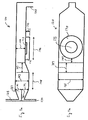
- FIG. 1a shows MOCVD reactor 120 in side view with exhaust line 180.
- MOCVD reactor 120 is a cold wall, quartz reactor.
- Group III source injection occurs at inlet 125 and Group V source injection occurs at inlet 130.
- Group III and Group V gases begin mixing after passing from outlets 187 and 188.
- Outlets 187 and 188 are both approximately 13 cm x 2 cm rectangles.
- Vertical height 143 of MOCVD reactor 120 is approximately 4.5 cm while dimension 144 is approximately 3 cm.
- Dimension 148 is approximately 7 cm and is the distance from where the Group III and Group V gases begin to mix to where the vertical constriction of MOCVD reactor 120 starts.
- Dimension 147 is approximately 7 cm and Si-coated graphite susceptor 170 has diameter 146 of approximately 11 cm with thickness 145 of approximately 1.5 cm. Substrate 175 is positioned on susceptor 170 as shown in FIGs. 1a and 1b . With reference to FIG. 1b , lateral dimension 185 of MOCVD reactor 120 is approximately 13 cm while dimension 149 is approximately 1.5 cm.
- FIG. 2 shows an arrangement of the chemicals and lines feeding into MOCVD reactor 120.
- MOCVD reactor 120 is typically a cold wall, quartz reactor.
- Valves 250, 251, 252 and 253 control and direct flow from tanks 231, 232, 233, and 234, respectively.
- Valves 254, 255, 256, 257, 258, 259 and 260 control and direct flow from bubblers 235, 236, 237, 238, 239, 240 and 241, respectively.
- Inlet 210 serves to introduce H 2 carrier gas into MOCVD reactor 120 via line 212 to inlet 130 of MOCVD reactor 120.
- Line 212 serves as well for typically introducing Tertiarybutylarsine (TBAs) from bubbler 235 and Dimethylhydrazine (DMHy) from bubbler 236 into MOCVD reactor 120 via inlet 130.
- Valves 254 and 255 direct flow from bubblers 235 and 236, respectively, into either line 212 or vent line 220.
- Vent lines 220 connect to exhaust line 180.
- Line 221 serves to introduce H 2 into bubblers 235 and 236 while line 222 serves to introduce H 2 into bubblers 237, 238, 239, 240 and 241.
- Line 211 serves to introduce NH 3 from tank 231, AsH 3 from tank 232, PH 3 from tank 233 and Si 2 H 6 from tank 234 into MOVCD reactor 120 via inlet 130.
- Valves 250, 251, 252 and 253 direct flow from tanks 231, 232, 233 and 234, respectively, into either line 211 or vent line 220.
- Line 213 serves to typically introduce Trimethylgalium (TMGa) from bubbler 237, Triethylgallium (TEGa) from bubbler 238, Trimethyaluminum (TMA1) from bubbler 239, Trimethylindium (TMIn) from bubbler 240 and CBr 4 from bubbler 241 into MOCVD reactor 120 via inlet 125.
- Valves 256, 257, 258, 259 and 260 direct flow from bubblers 237, 238, 239, 240 and 241, respectively, into either line 213 or vent line 220. Note that there is no back flow in any of the lines since a mechanical pump (not shown) maintains the pressure inside reactor 120 at about 100 mbar.
- asymmetric VCSEL structure 305 shown in FIG. 3 is grown by using an MOCVD reactor such as MOCVD reactor 120 shown in FIGs. 1a and 1b .
- MOCVD reactor 120 Si-doped GaAs buffer layer 325 with a doping level typically in the range of 1.0 x 10 17 - 5.0 x 10 18 cm -3 is grown on GaAs substrate 320 to a thickness typically in the range of about 1000 - 5000 ⁇ at a typical temperature of about 600 - 800 °C.
- bottom n-type DBR mirror structure 330 is grown.
- N-type DBR mirror structure 330 is typically made up of about 35- 45 pairs of alternating layers of which Si-doped Al 0.9 Ga 0.1 As layer 331 and Si-doped GaAs layer 332 are representative with Si-doping typically in the range of 5.0 x 10 17 - 5.0 x 10 18 cm -3 .
- the grading profile is typically linear with distance from the interface.
- the grading serves to lower the hetero barrier between AlGaAs and GaAs layers resulting in lower operating voltages for the VCSEL device.
- the total amount of TMA1 typically supplied to MOCVD reactor 120 for growth of all Si-doped Al 0.9 Ga 0.1 As type layers 331 layers in n-type DBR mirror structure 330 is about 7 x 10 -3 mol.
- GaAs layer 335 is grown to a thickness in the range of about 50 -300 ⁇ at a temperature typically in the range of 600 - 800 °C.
- GaAs 1- x N x layer 336 is grown to a typical thickness of about 600 ⁇ where x is between 0 and 0.1.
- TMGa, 100 sccm, AsH 3 , and 500 sccm of NH 3 are supplied for about 4 minutes while the growth temperature is decreased to about 500 - 550 °C from 600- 800 °C in growing GaAs 1-x N x layer 336.
- the total amount of NH 3 introduced is typically about 8 x 10 -2 mol which is approximately ten times larger than the amount of TMA1 that is typically supplied for the growth of all Si-doped Al 0.9 Ga 0.1 As type layers 331 that make up DBR mirror structure 330 when using MOCVD reactor 120.
- NH 3 serves to getter the Al which would interfere with growth of InGaAsN quantum well active layers 350, 360 and 370 and can be replaced, for example, by Monomethylamine, Dimethylamine, Diethylamine, Tertiarybutylamine, hydrazine, Monomethylhydrazine, Dimethylhydrazine, Tertiarybutylhydrazine or Phenylhydrazine.
- GaAs 1-x N x in layer 336 may be replaced, for example, by GaAsNP, InGaAsPN, InGaAsN, InGaAsP or similar compositions.
- GaAs cladding layer 337 is grown over GaAs 1-x N x layer 336 to a typical thickness in the range of about 700-900 ⁇ but greater than about 200 ⁇ .
- Si-doped GaAs 1-x N x layer 336 may be grown embedded in one or more of Si-doped GaAs layers 332 of DBR mirror structure 330 having a typical thickness of about 600 ⁇ .
- an Si-doped AlGa As 1-x N x layer may be grown embedded in one or more of Si-doped Al 0.9 Ga 0.1 As layers 331 having a typical thickness of about 600 ⁇ .
- InGaAsN quantum well active layer 350 is grown to a thickness in the range of about 60 - 100 ⁇ using TEGa, TMIn, TBAs and DMHy.
- the ratio of DMHy/(DMHy + TBAs) in the range of about 0.95 - 0.99 is typically used for growth of InGaAsN quantum well active layer 350.
- GaAs barrier layer 351 is grown over InGaAsN quantum well active layer 350 to a thickness in the range of 50 - 300 ⁇ .
- quantum well active layer 360 is grown to a typical thickness in the range of about 60 -100 ⁇ using TEGa, TMIn, TBAs and DMHy.
- the ratio of DMHy/(DMHy + TBAs) in the range of about 0.95 - 0.99 is typically used for growth of InGaAsN quantum well active layer 360.
- GaAs barrier layer 361 is grown over InGaAsN quantum well active layer 360 to a thickness in the range of 50 - 300 ⁇ .
- InGaAsN quantum well active layer 370 is grown to a thickness in the range of about 60 - 100 ⁇ using TEGa, TMIn, TBAs and DMHy.
- the ratio of DMHy/(DMHy + TBAs) in the range of about 0.95 - 0.99 is typically used for growth of InGaAsN quantum well active layer 370.
- the total number of quantum wells as well as the thickness of quantum well active layers 350, 360, 370 and barrier layers 351, 361 may be adjusted to obtain the best results.
- the distance from the first quantum well active layer, for example, quantum well active layer 350 to the last quantum well active layer, for example, quantum well active layer 370 is fixed to be no greater than 600 ⁇ .
- the thickness of GaAs cladding layer 337 and GaAs layer 380 is typically adjusted appropriately in order to put the layers extending from the first quantum well layer to the last quantum well layer, for example, quantum well active layer 350 to quantum well active layer 370, at a maximum of the standing wave cavity.
- GaAs layer 380 is grown to thickness in the range of about 1500-1700 ⁇ while the temperature is typically increased to about 600 - 800 °C. Then p-type DBR mirror structure 390 is grown.
- P-type DBR mirror structure 390 is made up of about 20-35 pairs of alternating layers of which C-doped Al x Ga 1-x As layer 391 and C-doped GaAs layer 392 are representative layer pairs with x typically in the range of between about 0.8 and 1 and with C-doping typically in the range of 5.0 x 10 17 - 5.0 x 10 18 cm -3 .
- C-doped Al x Ga 1-x As layer 391 is grown to a typical thickness corresponding to one quarter of the emission wavelength.
- C-doped Al y Ga 1-y As layer 392 where y is typically in the range of 0 to less than 0.2 is grown to a typical thickness corresponding to one quarter of the emission wavelength with about 100-300 ⁇ of linear grading at each interface.
- the growth is completed by growing heavily C-doped GaAs contact layer 395 to a thickness in the range of about 500-1000 ⁇ .
- C-doped GaAs contact layer 395 is typically doped in the range of 5.0 x 10 18 - 1.0 x 10 20 cm -3 .
- C-doped Al x Ga 1-x As layer 385 is used to make the laterally oxidized layer for the purposes of optical confinement and current confinement, if desired.
- the value of x for C-doped Al x Ga 1-x As layer 385 is selected to be higher than the value of x selected for typical C-doped Al x Ga 1-x As layer 391 since the rate of oxidation is strongly dependent on the Al content of C-doped Al x Ga 1-x As layer 385. See, for example, U. S. Patent No. 5,896,408 , incorporated by reference in its entirety, for details. Ion implantation is used to realize current confinement either alone or in conjunction with laterally oxidized layer 385.
- a reverse-biased tunnel junction can be utilized as a p-contact instead of C-doped GaAs contact layer 395. This allows high current flow at a low bias voltage as well as low absorption of emission light in n-type DBR 490.
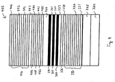
- FIG. 4 shows asymmetric VCSEL structure 405 utilizing a reverse-biased tunnel junction.
- Si-doped GaAs buffer layer 325 with a doping level typically in the range of 1.0 x 10 17 - 5.0 x 10 18 cm -3 is grown on GaAs substrate 320 to a thickness in the range of 1000 - 5000 ⁇ at a temperature of about 600 - 800 °C.
- N-type DBR mirror structure 330 is typically made up of about 35- 45 pairs of alternating layers of which Si-doped Al x Ga 1-x As layer 331 and Si-doped GaAs layer 332 are typical with Si-doping typically in the range of 5.0 x 10 17 - 5.0 x 10 18 cm -3 .
- Si-doped Al x Ga 1-x As layer 331 where x is between about 0.8 and 1.0 is grown to a thickness corresponding to one quarter wavelength (of emission wavelength) and Si-doped GaAs layer 332 is also grown to a thickness corresponding to one quarter wavelength length with about 100 - 300 ⁇ of grading at each interface.
- the grading profile is typically linear with distance from the interface.
- the grading serves to lower hetero barrier between AlGaAs and GaAs layers resulting in lower operating voltages for the VCSEL device.
- the total amount of TMA1 typically supplied to MOCVD reactor 120 for growth of all Si-doped Al 0.9 Ga 0.1 As type layers 331 in n-type DBR mirror structure 330 is about 7 x 10 -3 mol.
- GaAs layer 335 is grown to a thickness in the range of about 50 -300 ⁇ .
- GaAs 1-x N x non-active layer 336 is grown to a typical thickness of about 600 ⁇ where x is between 0 and 0.1.
- TMGa, 100 sccm, AsH 3 , and 500 sccm of NH 3 are supplied for about 4 minutes while the growth temperature is decreased to about 500 - 550 °C from 600- 800 °C in growing GaAs 1-x N x layer 336.
- the total amount of NH 3 introduced is typically about 8 x 10 -3 mol which is approximately ten times larger than the amount of TMAI that is typically supplied for the growth of all Si-doped Al 0.9 Ga 0.1 As type layers 331 that make up DBR mirror structure 330 when using MOCVD reactor 120.
- NH 3 serves to getter the Al which would interfere with growth of InGaAsN quantum well active layers 350, 360 and 370 and can be replaced, for example, by Monomethylamine, Dimethylamine, Diethylamine, Tertiarybutylamine, hydrazine, Monomethylhydrazine, Dimethylhydrazine, Tertiarybutylhydrazine or Phenylhydrazine .
- GaAs 1-x N x in layer 336 may be replaced, for example, by GaAsNP, InGaAsPN, InGaAsN, INGaAsP or similar compositions.
- GaAs cladding layer 337 is grown over GaAs 1-x N x non-active layer 336 to a typical thickness in the range of about 700-900 ⁇ but greater than about 200 ⁇ so that the combined thickness of GaAs 1-x N x non-active layer 336 and GaAs cladding layer 337 is in the range of from about 1000-2000 ⁇ .
- active layer 350 is grown to a thickness in the range of about 60 - 100 ⁇ using TEGa, TMIn, TBAs and DMHy.
- the ratio of DMHy/(DMHy + TBAs) in the range of about 0.95 - 0.99 is typically used for growth of InGaAsN active layer 350.
- GaAs barrier layer 351 is grown over InGaAsN active layer 650 to a thickness in the range of 100 - 300 ⁇ .
- active layer 360 is grown to a thickness in the range of about 60 -100 ⁇ using TEGa, TMIn, TBAs and DMHy.
- the ratio of DMHy/(DMHy + TBAs) in the range of about 0.95 ⁇ 0.99 is typically used for growth of InGaAsN active layer 360.
- GaAs barrier layer 361 is grown over InGaAsN quantum well active layer 360 to a thickness in the range of 100 - 300 ⁇ .
- quantum well active layer 370 is grown to a thickness in the range of about 60 - 100 ⁇ using TEGa, TMIn, TBAs and DMHy.
- the ratio of DMHy/(DMHy + TBAs) in the range of about 0.95-0.99 is typically used for growth of InGaAsN active layer 370.
- the total number of quantum wells as well as quantum well active layer and barrier layer thickness may be adjusted to obtain the best results.
- the distance from the first quantum active layer to the last quantum well active layer is fixed to be no more than about 600 ⁇ and the thickness of GaAs cladding layer 337 and GaAs layer 380 is adjusted appropriately in order to put the active region at a maximum of the standing wave cavity.
- GaAs layer 380 is grown to thickness in the range of about 1000 ⁇ 2000 ⁇ while the temperature is typically increased to about 600 - 800 °C. Then C-doped Al 0.9 Ga 0.1 As layer 481 is grown to a typical thickness of about 260 ⁇ , C-doped Al x Ga 1-x As layer 482 is grown to a typical thickness of about 100 ⁇ and C-doped Al 0.9 Ga 0.1 As layer 483 is grown to atypical thickness of about 260 ⁇ to make the laterally oxidized layer structure for the purpose of providing optical confinement and current confinement.
- C-doped GaAs layer 484 is grown to a typical thickness in the range of 50 ⁇ 100 A.
- the value of x for C-doped Al x Ga 1-x As layer 482 is selected to be higher than the value of x selected for any other C-doped Al x Ga 1-x As layers in the structure since the rate of oxidation is strongly dependent on the Al content of C-doped Al x Ga 1-x As layer 482. See, for example, U. S. Patent No. 5,896,408 , incorporated by reference in its entirety, for details. Ion implantation may also be used to realize current confinement either alone or in conjunction with laterally oxidized layer structure.
- the tunnel junction which consists of heavily C-doped GaAs layer 485 grown to a typical thickness of about 200A with C-doping typically in the range of about 2.0 x 10 19 to 2.0 x 10 20 cm -3 and heavily Si-doped In x Ga 1-x As layer 486, where x is in the range of about 0 to 0.2, is grown to a typical thickness of about 100 - 200 ⁇ with Si doping typically in the range of about 1.0 x 10 18 to 1.0 x 10 20 cm -3 .
- tunnel junction allows better lateral current spreading at the n-layers on the top of the tunnel junction as well as much lower absorption loss of emission light at top n-type DBR mirror structure 490 compared to a p-type DBR mirror structure.
- Si-doped GaAs layer 487 with a thickness in the range of about 500 ⁇ 600A is grown on In x Ga 1- x As layer 486 with Si doping typically in the range of about 1.0 x 10 17 to 1.0 x 10 18 cm -3 .
- the tunnel junction is located at a minimum of the standing wave in the laser cavity to minimize the absorption loss at the tunnel junction by adjusting the thickness of the GaAs layer 380 and Si-doped GaAs layer 487.
- N-type DBR mirror structure 490 is made up of about 20-35 pairs of alternating layers of which Si-doped Al x Ga 1- x As layer 491 and Si-doped GaAs layer 492 are typical layer pairs with x between 0.8 and 1 and with Si-doping typically in the range of 5.0 x 10 17 - 5.0 x 10 18 cm -3 .
- Si-doped Al x Ga 1-x As layer 491 is grown to a thickness corresponding to one quarter of the emission wavelength.
- Si -doped GaAs layer 492 is also grown to a thickness corresponding to one quarter of the emission wavelength with about 100-300 ⁇ of linear grading at each interface.
- Si -doped GaAs contact layer 406 is grown heavily Si -doped GaAs contact layer 406 to a thickness in the range of about 500-1000 ⁇ .
- Si -doped GaAs contact layer 406 is typically doped in the range of 5.0 x 10 18 - 1.0 x 10 20 cm -3 .
Claims (9)
- Structure laser à cavité verticale asymétrique et à émission par la surface comprenant :un substrat (320) ;une pluralité de couches semiconductrices formée sur ledit substrat ;l'une desdites couches semiconductrices comprenant une couche active (350, 360, 370) de puits quantique ;un premier réflecteur (330) comprenant de l'Al situé sur un côté de ladite couche active de puits quantique et un deuxième réflecteur (390) situé sur le côté opposé de ladite couche active de puits quantique ; etl'une desdites couches semiconductrices étant une couche non-active (336) comprenant du nitrogène, ladite couche non-active comprenant du nitrogène étant située entre ladite couche active de puits quantique et ledit premier réflecteur (330), caractérisée par le fait queladite couche non-active (336) est séparée de ladite couche active (350, 360, 370) de puits quantique d'une distance d'au moins environ 200 Å.
- Structure laser à cavité verticale asymétrique et à émission par la surface selon la revendication 1, dans laquelle ladite couche non-active (336) comprenant du nitrogène est suffisamment épaisse pour éliminer par effet getter l'Al contenu dans le premier réflecteur (330) de façon à ce que ledit Al contenu dans le premier réflecteur (330) n'interfère pas avec l'expansion de la couche active (350, 360, 370) de puits quantique.
- Structure laser à cavité verticale asymétrique et à émission par la surface selon la revendication 1 ou la revendication 2, dans laquelle ladite couche non-active (336) n'est pas appariée par une couche non-active correspondante contenant du nitrogène située entre la couche active (350, 360, 370) de puits quantique et ledit deuxième réflecteur (390), créant ainsi l'asymétrie de la structure laser à cavité verticale asymétrique et à émission par la surface.
- Structure laser à cavité verticale asymétrique et à émission par la surface selon l'une des revendications précédentes dans laquelle ladite couche non-active (336) comprend de l'Al, du Ga, de l'As et du N.
- Structure laser à cavité verticale asymétrique et à émission par la surface selon l'une des revendications précédentes dans laquelle ladite couche non-active (336) comprend du GaAs1-xNx.
- Structure laser à cavité verticale asymétrique et à émission par la surface selon la revendication 5 dans laquelle la valeur de x est comprise entre 0 et 0,1.
- Structure laser à cavité verticale asymétrique et à émission par la surface selon l'une des revendications précédentes dans laquelle ladite couche non-active (336) comprenant du nitrogène a une épaisseur d'environ 600 Ǻ.
- Structure laser à cavité verticale asymétrique et à émission par la surface selon l'une des revendications précédentes dans laquelle ladite couche active (350, 360, 370) de puits quantique comprend de l'In, du Ga, de l'As et du N.
- Structure laser à cavité verticale asymétrique et à émission par la surface selon l'une des revendications précédentes dans laquelle deux parmi ladite pluralité de couches semiconductrices comprend une jonction tunnel.
Applications Claiming Priority (2)
| Application Number | Priority Date | Filing Date | Title |
|---|---|---|---|
| US10/106,678 US6813295B2 (en) | 2002-03-25 | 2002-03-25 | Asymmetric InGaAsN vertical cavity surface emitting lasers |
| US106678 | 2002-03-25 |
Publications (3)
| Publication Number | Publication Date |
|---|---|
| EP1349246A2 EP1349246A2 (fr) | 2003-10-01 |
| EP1349246A3 EP1349246A3 (fr) | 2005-06-29 |
| EP1349246B1 true EP1349246B1 (fr) | 2008-12-17 |
Family
ID=27804354
Family Applications (1)
| Application Number | Title | Priority Date | Filing Date |
|---|---|---|---|
| EP02023534A Expired - Fee Related EP1349246B1 (fr) | 2002-03-25 | 2002-10-22 | Laser InGaAsN assymétrique à émission de surface à cavité verticale |
Country Status (4)
| Country | Link |
|---|---|
| US (1) | US6813295B2 (fr) |
| EP (1) | EP1349246B1 (fr) |
| JP (1) | JP2003298187A (fr) |
| DE (1) | DE60230383D1 (fr) |
Families Citing this family (8)
| Publication number | Priority date | Publication date | Assignee | Title |
|---|---|---|---|---|
| JP4722404B2 (ja) * | 2004-02-24 | 2011-07-13 | 日本電信電話株式会社 | 長波長帯面発光半導体レーザ |
| US7372886B2 (en) | 2004-06-07 | 2008-05-13 | Avago Technologies Fiber Ip Pte Ltd | High thermal conductivity vertical cavity surface emitting laser (VCSEL) |
| US8253166B2 (en) * | 2004-09-14 | 2012-08-28 | Finisar Corporation | Band offset in AlInGaP based light emitters to improve temperature performance |
| DE102005004582A1 (de) * | 2005-01-26 | 2006-07-27 | Philipps-Universität Marburg | III/V-Halbleiter |
| KR101320836B1 (ko) * | 2005-01-26 | 2013-10-22 | 필립스-유니버시태트 마르부르크 | Ⅲ/ⅴ 반도체 |
| JPWO2007135772A1 (ja) | 2006-05-19 | 2009-10-01 | 日本電気株式会社 | 発光素子 |
| US8355421B2 (en) * | 2009-09-16 | 2013-01-15 | Furukawa Electric Co., Ltd | Vertical-cavity surface emitting laser |
| RU2672776C2 (ru) * | 2014-02-25 | 2018-11-19 | Конинклейке Филипс Н.В. | Светоизлучающие полупроводниковые устройства с геттерным слоем |
Family Cites Families (20)
| Publication number | Priority date | Publication date | Assignee | Title |
|---|---|---|---|---|
| US50934A (en) | 1865-11-14 | Improvement in devices for opening artesian wells | ||
| GB2277405A (en) * | 1993-04-22 | 1994-10-26 | Sharp Kk | Semiconductor colour display or detector array |
| US5912913A (en) * | 1995-12-27 | 1999-06-15 | Hitachi, Ltd. | Vertical cavity surface emitting laser, optical transmitter-receiver module using the laser, and parallel processing system using the laser |
| JPH09213918A (ja) * | 1996-02-01 | 1997-08-15 | Furukawa Electric Co Ltd:The | 光電子集積回路素子 |
| JP3788831B2 (ja) * | 1996-08-30 | 2006-06-21 | 株式会社リコー | 半導体素子およびその製造方法 |
| JP3449516B2 (ja) * | 1996-08-30 | 2003-09-22 | 株式会社リコー | 半導体多層膜反射鏡および半導体多層膜反射防止膜および面発光型半導体レーザおよび受光素子 |
| US6304588B1 (en) * | 1997-02-07 | 2001-10-16 | Xerox Corporation | Method and structure for eliminating polarization instability in laterally-oxidized VCSELs |
| KR100413792B1 (ko) * | 1997-07-24 | 2004-02-14 | 삼성전자주식회사 | 질화갈륨 층과 공기층이 반복 적층된 분산브래그 반사기를구비한 단파장 면발광 반도체 레이저장치 및 그 제조 방법 |
| US5903586A (en) | 1997-07-30 | 1999-05-11 | Motorola, Inc. | Long wavelength vertical cavity surface emitting laser |
| US5978398A (en) * | 1997-07-31 | 1999-11-02 | Motorola, Inc. | Long wavelength vertical cavity surface emitting laser |
| US6015979A (en) * | 1997-08-29 | 2000-01-18 | Kabushiki Kaisha Toshiba | Nitride-based semiconductor element and method for manufacturing the same |
| US6207973B1 (en) * | 1998-08-19 | 2001-03-27 | Ricoh Company, Ltd. | Light emitting devices with layered III-V semiconductor structures |
| US6238944B1 (en) * | 1999-12-21 | 2001-05-29 | Xerox Corporation | Buried heterostructure vertical-cavity surface-emitting laser diodes using impurity induced layer disordering (IILD) via a buried impurity source |
| AU2001271279A1 (en) * | 2000-05-31 | 2001-12-11 | Sandia Corporation | Long wavelength vertical cavity surface emitting laser |
| US6931042B2 (en) * | 2000-05-31 | 2005-08-16 | Sandia Corporation | Long wavelength vertical cavity surface emitting laser |
| JP3735047B2 (ja) * | 2000-07-31 | 2006-01-11 | 古河電気工業株式会社 | 半導体レーザ素子及びその作製方法 |
| KR100374796B1 (ko) * | 2001-02-02 | 2003-03-03 | 삼성전기주식회사 | P형 전극과 활성층 사이에 효과적인 정공 확산을 위한 스페이서를 구비하는 GaN 면 발광 레이저 다이오드 및그 제조 방법 |
| JP2003017812A (ja) * | 2001-04-25 | 2003-01-17 | Furukawa Electric Co Ltd:The | 半導体レーザ素子 |
| US6680964B2 (en) * | 2001-12-07 | 2004-01-20 | Agilent Technologies, Inc. | Moisture passivated planar index-guided VCSEL |
| US6455340B1 (en) * | 2001-12-21 | 2002-09-24 | Xerox Corporation | Method of fabricating GaN semiconductor structures using laser-assisted epitaxial liftoff |
-
2002
- 2002-03-25 US US10/106,678 patent/US6813295B2/en not_active Expired - Fee Related
- 2002-10-22 DE DE60230383T patent/DE60230383D1/de not_active Expired - Fee Related
- 2002-10-22 EP EP02023534A patent/EP1349246B1/fr not_active Expired - Fee Related
-
2003
- 2003-03-25 JP JP2003082487A patent/JP2003298187A/ja not_active Withdrawn
Also Published As
| Publication number | Publication date |
|---|---|
| EP1349246A3 (fr) | 2005-06-29 |
| JP2003298187A (ja) | 2003-10-17 |
| EP1349246A2 (fr) | 2003-10-01 |
| US6813295B2 (en) | 2004-11-02 |
| DE60230383D1 (de) | 2009-01-29 |
| US20030179801A1 (en) | 2003-09-25 |
Similar Documents
| Publication | Publication Date | Title |
|---|---|---|
| EP1348778B1 (fr) | Méthode pour obtenir un semiconducteur InGaAsN de haute qualité | |
| US6207973B1 (en) | Light emitting devices with layered III-V semiconductor structures | |
| US7235816B2 (en) | Semiconductor light emitter | |
| US6934312B2 (en) | System and method for fabricating efficient semiconductor lasers via use of precursors having a direct bond between a group III atom and a nitrogen atom | |
| US6377598B1 (en) | Semiconductor light-emitting device and method for producing the same | |
| EP1043819B1 (fr) | Conception et réalisation d'une diode laser à guide asymétrique à base de nitrure | |
| EP0822630A1 (fr) | Laser à l'émission de surface à cavité verticale à grande longueurs d'ondes infrarouges sur un substrat de GaAs | |
| JP2001185497A (ja) | 化合物半導体の結晶成長方法、量子井戸構造、及び化合物半導体装置 | |
| US20210194216A1 (en) | Stacked semiconductor lasers with controlled spectral emission | |
| TWI383555B (zh) | 用於長波長活性區域之深井結構的方法及結構 | |
| EP1349246B1 (fr) | Laser InGaAsN assymétrique à émission de surface à cavité verticale | |
| JP2006024713A (ja) | 窒化物半導体素子およびその製造方法 | |
| JP2000277867A (ja) | 半導体レーザ装置 | |
| JP4253207B2 (ja) | 半導体発光素子の製造方法および半導体発光素子および面発光型半導体レーザ素子の製造方法および面発光型半導体レーザ素子および面発光型半導体レーザアレイおよび光送信モジュールおよび光送受信モジュールおよび光通信システム | |
| Yue et al. | Low threshold current 1.3-μm GaInNAs VCSELs grown by MOVPE | |
| US20050243881A1 (en) | InAlAs having enhanced oxidation rate grown under very low V/III ratio | |
| JP4636309B2 (ja) | 半導体レーザ素子の製造方法 | |
| Gouardes et al. | GaInAs-GaInNAs-GaInAs intermediate layer structure for long wavelength lasers | |
| Kondo et al. | Temperature characteristics of 1.16 um highly strained GaInAs/GaAs VCSELs | |
| CN116231451A (zh) | 垂直腔面发射激光器的制备方法及垂直腔面发射激光器 | |
| JP2001339120A (ja) | 化合物半導体素子およびその製造方法 | |
| JP4068535B2 (ja) | 半導体レーザ素子、光半導体素子およびその製造方法 | |
| JP4193245B2 (ja) | 化合物半導体素子 | |
| JP2008098682A (ja) | 半導体発光素子 | |
| Armour et al. | Application of metal-organic chemical vapor deposition to vertical-cavity surface-emitting lasers |
Legal Events
| Date | Code | Title | Description |
|---|---|---|---|
| PUAI | Public reference made under article 153(3) epc to a published international application that has entered the european phase |
Free format text: ORIGINAL CODE: 0009012 |
|
| AK | Designated contracting states |
Kind code of ref document: A2 Designated state(s): AT BE BG CH CY CZ DE DK EE ES FI FR GB GR IE IT LI LU MC NL PT SE SK TR |
|
| AX | Request for extension of the european patent |
Extension state: AL LT LV MK RO SI |
|
| PUAL | Search report despatched |
Free format text: ORIGINAL CODE: 0009013 |
|
| AK | Designated contracting states |
Kind code of ref document: A3 Designated state(s): AT BE BG CH CY CZ DE DK EE ES FI FR GB GR IE IT LI LU MC NL PT SE SK TR |
|
| AX | Request for extension of the european patent |
Extension state: AL LT LV MK RO SI |
|
| 17P | Request for examination filed |
Effective date: 20051201 |
|
| AKX | Designation fees paid |
Designated state(s): DE FR GB |
|
| RAP1 | Party data changed (applicant data changed or rights of an application transferred) |
Owner name: AVAGO TECHNOLOGIES ECBU IP (SINGAPORE) PTE. LTD. |
|
| GRAP | Despatch of communication of intention to grant a patent |
Free format text: ORIGINAL CODE: EPIDOSNIGR1 |
|
| GRAS | Grant fee paid |
Free format text: ORIGINAL CODE: EPIDOSNIGR3 |
|
| GRAA | (expected) grant |
Free format text: ORIGINAL CODE: 0009210 |
|
| AK | Designated contracting states |
Kind code of ref document: B1 Designated state(s): DE FR GB |
|
| REG | Reference to a national code |
Ref country code: GB Ref legal event code: FG4D |
|
| REF | Corresponds to: |
Ref document number: 60230383 Country of ref document: DE Date of ref document: 20090129 Kind code of ref document: P |
|
| PLBE | No opposition filed within time limit |
Free format text: ORIGINAL CODE: 0009261 |
|
| STAA | Information on the status of an ep patent application or granted ep patent |
Free format text: STATUS: NO OPPOSITION FILED WITHIN TIME LIMIT |
|
| 26N | No opposition filed |
Effective date: 20090918 |
|
| REG | Reference to a national code |
Ref country code: FR Ref legal event code: ST Effective date: 20100630 |
|
| PG25 | Lapsed in a contracting state [announced via postgrant information from national office to epo] |
Ref country code: FR Free format text: LAPSE BECAUSE OF NON-PAYMENT OF DUE FEES Effective date: 20091102 Ref country code: DE Free format text: LAPSE BECAUSE OF NON-PAYMENT OF DUE FEES Effective date: 20100501 |
|
| PGFP | Annual fee paid to national office [announced via postgrant information from national office to epo] |
Ref country code: GB Payment date: 20121017 Year of fee payment: 11 |
|
| REG | Reference to a national code |
Ref country code: GB Ref legal event code: 732E Free format text: REGISTERED BETWEEN 20130725 AND 20130731 |
|
| GBPC | Gb: european patent ceased through non-payment of renewal fee |
Effective date: 20131022 |
|
| PG25 | Lapsed in a contracting state [announced via postgrant information from national office to epo] |
Ref country code: GB Free format text: LAPSE BECAUSE OF NON-PAYMENT OF DUE FEES Effective date: 20131022 |