EP1348976A1 - Verfahren und Vorrichtungen zum Bestimmen der Funkempfangsrichtung in einem Mobilkommunikationsnetz - Google Patents
Verfahren und Vorrichtungen zum Bestimmen der Funkempfangsrichtung in einem Mobilkommunikationsnetz Download PDFInfo
- Publication number
- EP1348976A1 EP1348976A1 EP02360074A EP02360074A EP1348976A1 EP 1348976 A1 EP1348976 A1 EP 1348976A1 EP 02360074 A EP02360074 A EP 02360074A EP 02360074 A EP02360074 A EP 02360074A EP 1348976 A1 EP1348976 A1 EP 1348976A1
- Authority
- EP
- European Patent Office
- Prior art keywords
- radio
- reception
- mobile communication
- base station
- communication terminal
- Prior art date
- Legal status (The legal status is an assumption and is not a legal conclusion. Google has not performed a legal analysis and makes no representation as to the accuracy of the status listed.)
- Granted
Links
- 238000010295 mobile communication Methods 0.000 title claims abstract description 63
- 238000000034 method Methods 0.000 title claims abstract description 35
- 230000005540 biological transmission Effects 0.000 claims description 17
- 238000010586 diagram Methods 0.000 description 5
- 238000004364 calculation method Methods 0.000 description 4
- 230000001413 cellular effect Effects 0.000 description 4
- 238000005259 measurement Methods 0.000 description 3
- 230000015572 biosynthetic process Effects 0.000 description 2
- 238000004891 communication Methods 0.000 description 2
- 230000001419 dependent effect Effects 0.000 description 2
- 230000000694 effects Effects 0.000 description 2
- 238000005562 fading Methods 0.000 description 2
- 230000000155 isotopic effect Effects 0.000 description 2
- 230000011664 signaling Effects 0.000 description 2
- 238000012935 Averaging Methods 0.000 description 1
- 238000009825 accumulation Methods 0.000 description 1
- 230000002238 attenuated effect Effects 0.000 description 1
- 230000009286 beneficial effect Effects 0.000 description 1
- 238000007796 conventional method Methods 0.000 description 1
- 238000011156 evaluation Methods 0.000 description 1
- 238000012854 evaluation process Methods 0.000 description 1
- 230000001771 impaired effect Effects 0.000 description 1
- 238000012804 iterative process Methods 0.000 description 1
- 230000004807 localization Effects 0.000 description 1
- 238000012544 monitoring process Methods 0.000 description 1
- 230000005855 radiation Effects 0.000 description 1
- 230000001360 synchronised effect Effects 0.000 description 1
- 238000012546 transfer Methods 0.000 description 1
- 230000000007 visual effect Effects 0.000 description 1
Images




Classifications
-
- H—ELECTRICITY
- H04—ELECTRIC COMMUNICATION TECHNIQUE
- H04W—WIRELESS COMMUNICATION NETWORKS
- H04W64/00—Locating users or terminals or network equipment for network management purposes, e.g. mobility management
-
- G—PHYSICS
- G01—MEASURING; TESTING
- G01S—RADIO DIRECTION-FINDING; RADIO NAVIGATION; DETERMINING DISTANCE OR VELOCITY BY USE OF RADIO WAVES; LOCATING OR PRESENCE-DETECTING BY USE OF THE REFLECTION OR RERADIATION OF RADIO WAVES; ANALOGOUS ARRANGEMENTS USING OTHER WAVES
- G01S1/00—Beacons or beacon systems transmitting signals having a characteristic or characteristics capable of being detected by non-directional receivers and defining directions, positions, or position lines fixed relatively to the beacon transmitters; Receivers co-operating therewith
- G01S1/02—Beacons or beacon systems transmitting signals having a characteristic or characteristics capable of being detected by non-directional receivers and defining directions, positions, or position lines fixed relatively to the beacon transmitters; Receivers co-operating therewith using radio waves
- G01S1/08—Systems for determining direction or position line
- G01S1/14—Systems for determining direction or position line using amplitude comparison of signals transmitted simultaneously from antennas or antenna systems having differently oriented overlapping directivity-characteristics
-
- H—ELECTRICITY
- H01—ELECTRIC ELEMENTS
- H01Q—ANTENNAS, i.e. RADIO AERIALS
- H01Q1/00—Details of, or arrangements associated with, antennas
- H01Q1/12—Supports; Mounting means
- H01Q1/22—Supports; Mounting means by structural association with other equipment or articles
- H01Q1/24—Supports; Mounting means by structural association with other equipment or articles with receiving set
- H01Q1/241—Supports; Mounting means by structural association with other equipment or articles with receiving set used in mobile communications, e.g. GSM
- H01Q1/246—Supports; Mounting means by structural association with other equipment or articles with receiving set used in mobile communications, e.g. GSM specially adapted for base stations
-
- G—PHYSICS
- G01—MEASURING; TESTING
- G01S—RADIO DIRECTION-FINDING; RADIO NAVIGATION; DETERMINING DISTANCE OR VELOCITY BY USE OF RADIO WAVES; LOCATING OR PRESENCE-DETECTING BY USE OF THE REFLECTION OR RERADIATION OF RADIO WAVES; ANALOGOUS ARRANGEMENTS USING OTHER WAVES
- G01S5/00—Position-fixing by co-ordinating two or more direction or position line determinations; Position-fixing by co-ordinating two or more distance determinations
- G01S5/02—Position-fixing by co-ordinating two or more direction or position line determinations; Position-fixing by co-ordinating two or more distance determinations using radio waves
- G01S5/12—Position-fixing by co-ordinating two or more direction or position line determinations; Position-fixing by co-ordinating two or more distance determinations using radio waves by co-ordinating position lines of different shape, e.g. hyperbolic, circular, elliptical or radial
Definitions
- the invention relates to a method for determining the Radio reception direction in the downward direction on one Base station location in a mobile communication network according to the Preamble of claim 1.
- the invention also relates to a Mobile communication network with devices, in particular with a Computer, a base station and a mobile communication terminal, to carry out the method according to the generic terms of sibling claims.
- Mobile communication networks In mobile communication networks, especially in cellular ones Mobile communication networks, such as the GSM (Global System for Mobile Communications) or UMTS (Universal Mobile Telecommunications System), it is important the current location to know the mobile subscriber. Of increasing interest are the so-called "location based services" which depend on the current location of the Mobile subscribers. To perform these and similar services too not only the radio cell or the radio field area is necessary to know where the radio subscriber is, but a more precise one Position determination up to a few meters. Various methods for this are already known. That's about it So-called triangulation method known in which the distances of the Mobile communication terminal to neighboring base stations can be determined by measuring radio signal propagation times, using hand the intersection points of corresponding distance radii of the current whereabouts is determined. To do this, however, both There is contact with at least two remote base stations. In addition, the radio transmitters of the base stations must be on top of each other be synchronized or at least the time differences between the transmission signals, especially between the symbols.
- GSM Global System
- the object of the invention is a method for determining the To introduce radio reception direction that is as simple as possible can still be accurate information about the actual Direction of radio reception delivers. Corresponding should also Devices for this are presented.
- the task is solved by a procedure with the characteristics according to Claim 1 and through a mobile communication network, a computer, a base station and a mobile communication terminal with the Features according to one of the independent claims.
- the respective Mobile communication terminal at least the reception level of the Radio signals are measured by a first and a second of the transmitting antenna are emitted.
- the two become measured reception levels formed a ratio value. This is is largely independent of the ruling ones Radio propagation conditions, especially from the path losses the radio links. An estimate is then made using this ratio value of azimuth angles for the direction of radio reception to be determined carried out.
- Mobile communication network contains a computer that is connected to the base station location and that of the two measured reception levels forms the ratio value and thus again estimates the azimuth angle.
- the invention can therefore be found at each individual radio base station location already complete. There is no contact with several Base stations required. Measured values are also used, namely the reception level of the radio signals, which in many cases is already for other purposes, such as determined for handover measurements must be and thus already exist in the mobile communication network. These measured values are e.g. as part of a so-called Measurement reports from the mobile communication terminals to the Fixed radio location transmitted.
- a ratio value is achieved that the reception level values impairing sizes are eliminated, especially for the Radio propagation conditions characteristic quantities, such as Radio field loss or path loss. These sizes are heavily dependent from the given situation, such as visual radio link, Radio shading, fading, reflections or waveguide effects.
- the Invention is based on the knowledge that the two together Ratio set reception levels are equally affected, if the two transmit antennas are in the same place, preferably on same antenna mast are mounted. In this case, through education of the ratio (quotient formation) a relative value is obtained, which is largely independent of the radio propagation conditions and which is a reliable estimate of the azimuth angle and determination the direction of radio reception. In addition, the quotient formation easy and quick to carry out. So overall a very easy one too Realizing but very reliable method proposed.
- the reference values are Transmission power values that correspond to the EIRP value (EIRP: effective isotopic radiated power - effective isotopic radiated power) correspond and which in the other directions the due to the Antenna diagram correspond to attenuated transmission power values.
- the reference values, which is the angle-dependent distribution of the Radiation power on the transmit antennas are also ins Relative to each other and are preferably in Lookup tables filed. So it is possible to get a quick and to carry out an effective look-up-table method which saves the computation effort reduced even further.
- ratio values on the Reception side measured values
- ratio values on the transmission side Reference values
- the transmitting antennas Sector antennas or group antennas are and if the Radio coverage areas are radio sectors, each one of the Sector antennas or group antennas are supplied.
- the two Transmitting antennas the radio signals of which measure the reception level two adjacent radio coverage areas supply, and if the mobile communication terminal at least in one of these two radio coverage areas. This will the most prevalent reception levels with each other Ratio set what the reliability of the calculation method continued to improve.
- one of the transmit antennas is an omnidirectional antenna, of which the entire area of the Base station is supplied, and if the others Transmitting antennas are sector or group antennas, of which sector-shaped radio coverage areas are covered.
- the reception levels measured by the mobile communication terminal that of both radio signals of the omnidirectional antennas and of Radio signals from the sector or group antenna originate.
- the direction of radio reception can also be determined take place within the respective radio coverage area from which the Mobile communication terminal is supplied directly, on the one hand the reception level with respect to the omnidirectional antenna (e.g. reception level on the broadcast signaling channel) and on the other Reception level of the coverage area (e.g. reception level on the News channel within the sector) is used.
- FIG. 1a shows the schematic structure of an inventive Mobile communication network with at least one Base station BS, which is connected to the core network CN of the Mobile communication network is connected.
- Base station BS To the Base station BS there is a base station BTS with three Radio transmitters T1, T2 and T3, which have different radio coverage areas (see S1 to S3 in Fig. 1 b) of the base station location BS supply.
- the radio transmitters do not have to be in one Base station are located, but can also be located in a different one Radio base station can be integrated. This can be the case if different radio transmission methods in the Radio coverage areas are used.
- Each of the radio transmitters T1, T2 or T3 transmits the via a transmission antenna here is a sector antenna 1, 2 or 3, in its radio coverage area Radio signals to mobile communication terminals, of which exemplary an MS is shown in Fig. 1 a. It is for calculation accuracy However, the method is advantageous if the transmitting antennas 1, 2 and 3 preferably in the same place, e.g. are mounted on an antenna mast.
- the mobile communication terminal MS shown here is in direct radio connection with the transmitter T1 of the base station BTS.
- the Base station is, among other things, with a computer C, which is located in Core network CN is connected.
- the computer is C in the integrated in the radio switching center (Mobile Switching Center) and now determines the according to the method described in detail later Direction of radio reception, by means of which e.g. the exact position of the Mobile communication terminal MS can finally be determined.
- the computer can also be installed in other places, such as in Radio access network, especially in the base station controller (base station controller) or in the radio network control (Radio Network Controller), also in data nodes, such as the Gateway GPRS Support Node (GPRS: General Packet Radio Service) or the Serving GPRS Support Node for the UMTS.
- GPRS Gateway GPRS Support Node
- GPRS General Packet Radio Service
- Figure 1 b shows a schematic top view of the structural Establishment of the base station BS, the three Radio coverage areas in the form of three contiguous Sectors S1, S2 and S3.
- Each of the sectors S1, S2 or S3 will supplied by a transmitting antenna, which as sector antenna 1, 2 or 3 with an opening angle of 120 ° is formed.
- the Mobile communication terminal MS is located directly in the Radio coverage area S1 and is in radio communication with the Base station (not shown here; see BTS in Fig. 1a) on the corresponding sector antenna. This means that this sector S1 the so-called "serving cell" or "active set” corresponds.
- the Radio signals are transmitted from the corresponding transmission antenna (see 1 in Fig. 1a) in the downward direction DL to the mobile communication terminal MS transfer. In the opposite direction, i.e. in the upward direction UL the mobile communication terminal MS sends its radio signals back to the Antenna.
- the radio reception direction D is now to be determined in the downward direction to then e.g. a position determination of the To enable mobile communication terminal MS.
- a position determination of the To enable mobile communication terminal MS This can for example, in that the Direction of radio reception D is determined and secondly the distance determined between the transmitting antenna and the mobile communication terminal MS is, which can be derived from the radio signal transit time TA, which in turn in Form of a so-called "timimg advance" or "round trip time” is specified.
- the distance corresponds to a radius around the center of the base station location BS.
- the radio reception direction D in turn is indicated by an azimuth angle A. On the basis of the radius and the angle then the position of the Determine mobile communication terminal MS exactly.
- the proposed invention is particularly directed to the determination of the Direction of radio reception.
- the sector-shaped ones are Radio coverage areas S1 to S3 aligned such that the Radio coverage area S1 with its main emission direction in the direction North shows, that is, shows where the azimuth angle A is 0 degrees is.
- the other sectors S2 and S3 offset by 120 degrees each therefore show 120 degrees or 240 in their main directions Degree.
- the mobile communication terminal MS is now inside of the radio field coverage area (radio sector) S1.
- the radio field attenuation should be known in order to measured reception level with the reference values of the Antenna diagram to be able to compare.
- they are Radio propagation conditions, in particular radio field attenuation, are not stable, but depending on occurring effects, such as Radio shading, reflections or fading and weather changes with fluctuating air humidity and temperature.
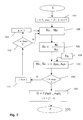
- FIG. 3 shows the flow chart for an inventive one Method 100 with steps 110 to 160, which here as iterative Process is formed.
- steps 110 to 160 which here as iterative Process is formed.
- a first step 110 set the following iteration parameters:
- a first index i which is also a loop counter, is added to its Initial value set to 1.
- a maximum value imax that is the number of Radio field areas (sectors) corresponds to 3.
- a second Index k is set to i + 1.
- the reception levels are first shown in measured in the different radio field areas. This will be a first Received level RLi and a second RLk determined. For the first run this means that the receive value RL1 for the first sector and the Receive value RL2 for the second sector (see S1 and S2 in FIG. 1b) be measured.
- a Ratio value Rik forms.
- the Ratio value R12 is formed from the ratio of RL1 to RL2.
- This calculated ratio value R12 is used later to determine the Azimuth angle used.
- Tik reference values are retrieved from a look-up table. These reference values give the characteristic of that in FIG. 4a shown reference curve again. In this first case it is that is, the reference values T12, which correspond to a curve corresponding to the Ratio of the transmission power level TP1 to the transmission power level TP2 equivalent. So there are the power level functions TP1 on the transmission side and TP2 for the sectors S1 and S2 (see FIGS. 1b and 2b and 2b) related to each other and as reference values T12 used.
- the ratio value R12 with the reference value T12 is compared and that where there is equality, a corresponding one Azimuth angle is determined.
- An azimuth angle Ap12 which is approximately -20 °
- an azimuth angle Aq12 which corresponds to approximately 57 ° determined (see also Figures 4a and 4b).
- Just one of those two Azimuth angle actually points in the direction of radio reception. The other is not relevant and arises from the ambiguous Evaluation process.
- step 160 is also illustrated in FIG. 5 shows where the estimated azimuth angles are plotted. At the Figure shows that in the range of 50 to 60 ° an accumulation of Estimates should be noted. By averaging the there The three available estimates result in one Radio reception direction D at 55 °.
- the values R23 and T23 refer exclusively to such Radio field areas (sectors) that the mobile communication terminal MS do not supply directly. So they are not serving cells or active sets, but rather so-called “neighbor cells” or “candidate / monitoring sets". These sectors are used by the Mobile communication terminal MS, which has no uplink signals there sends. You can now only monitor values like this, i.e. on the Downlink measured reception level, for determining the azimuth angle and use the direction of radio reception, especially if it is there are several such radio field areas (e.g. 5 for a sectorization of 60 degrees each). This has the advantage that the measured values are not of Influences due to one to be carried out in the serving cell Transmission power control on the local radio channels is impaired become. Because the radio signals in the "neighbor cells" from the Mobile communication device to be considered are radio channels on which is emitted with a constant (maximum) power.
- the method according to the invention can already be carried out on a single one Radio base site can be done so that there is none Radio contact with several radio base stations is required.
- the Estimation of the direction of radio reception becomes more precise the more Iterations can be performed. That in turn also depends on the number of existing sectors. However, it is also conceivable that not the reception values of different radio sectors be related to each other, but rather the Reception level emanating from an omnidirectional antenna and the Reception level from a sector antenna.
- the reception level on a radio channel is measured, which starts from an omnidirectional antenna (for example on the broadcast signaling channel, the so-called “broadcast control channel ”) and on the other hand the reception level of the corresponding sector antenna (for example on one of the Traffic channels) is measured.
- the reception level of the corresponding sector antenna for example on one of the Traffic channels.
- group antennas are used.
- the advantage is independent of the type of antennas used the invention already in that not absolute reception level but Ratio values (i.e. relative reception level) are calculated and with corresponding reference values are compared. That has among other things the advantage that the presented calculation method is independent of Radio propagation conditions.
- the method presented can be used to determine the position of Cellular devices are used. This is exemplified by the Figure 6 briefly describes: There is a cellular radio network assumed that each radio base station location over several Sector antennas. Will now be at several radio base stations, but at least on two neighboring ones, determining the respective one Direction of radio reception D carried out, a cross bearing is possible, with the finally the position of the mobile communication terminal MS be determined.
- a Radio base station location determined a receiving direction D equal to 55 ° and at a second base station location a reception direction of 290 ° and a reception direction of 345 ° at a third location.
- a triangle ideally an intersection
Landscapes
- Engineering & Computer Science (AREA)
- Computer Networks & Wireless Communication (AREA)
- Remote Sensing (AREA)
- Aviation & Aerospace Engineering (AREA)
- Physics & Mathematics (AREA)
- General Physics & Mathematics (AREA)
- Radar, Positioning & Navigation (AREA)
- Signal Processing (AREA)
- Mobile Radio Communication Systems (AREA)
- Radio Relay Systems (AREA)
- Radar Systems Or Details Thereof (AREA)
Abstract
Description
- Figur 1a,
- die den Aufbau eines erfindungsgemäßen Mobilkommunikationsnetzes zeigt;
- Figur 1 b,
- die die Struktur eines Funkfeststationsstandortes zeigt;
- Figur 2a und 2b,
- die den Sendeleistungspegelverlauf (Antennendiagramme oder Funktionen) der Funkversorgungsbereiche am Funkfeststationsstandort zeigen;
- Figur 3,
- die das Ablaufdiagramm eines erfindungsgemäßen Verfahrens zeigt;
- Figur 4a und 4b,
- die die zu erwartenden Verhältniswerte für verschiedene Azimutwinkel zeigen;
- Figur 5,
- die die Verteilung mehrerer Azimutwinkel und die daraus resultierende Funkempfangsrichtung zeigt; und
- Figur 6,
- die ein Prinzip zur genauen Positionsbestimmung einem zellularen Funknetz unter Zuhilfenahme des erfindungsgemäßen Verfahrens verdeutlicht.
Claims (10)
- Verfahren (100) zum Bestimmen der Funkempfangsrichtung (D) in Abwärtsrichtung (DL) an einem Funkfeststationsstandort (BS) in einem Mobilkommunikationsnetz, bei dem durch den Funkfeststationsstandort (BS) mindestens zwei räumliche Funkversorgungsbereiche (S1, S2, S3) abgedeckt werden, wobei in jedem Funkversorgungsbereich (S1) in der Abwärtsrichtung (DL) Funksignale mittels einer Sendeantenne (1) zum Empfang durch mindestens ein Mobilkommunikationsendgerät (MS) abgestrahlt werden,
dadurch gekennzeichnet, dass
von dem jeweiligen Mobilkommunikationsendgerät (MS) zumindest die Empfangspegel (RL1, RL2) der Funksignale gemessen werden (120), die von einer ersten (1) und von einer zweiten (2) der Sendeantennen abgestrahlt werden, dass aus den beiden gemessenen Empfangspegeln (RL1, RL2) ein Verhältniswert (R12) gebildet wird (130), und dass mittels des Verhältniswertes (R12) eine Schätzung von Azimutwinkeln (Ap12, Aq12) für die zu bestimmende Funksempfangsrichtung (D) durchgeführt wird (160). - Verfahren (100) nach Anspruch 1, dadurch gekennzeichnet, dass die Azimutwinkel (Ap12, Aq12) geschätzt werden, indem der gebildete Verhältniswert (R12) mit vorgegebenen Referenzwerten (T12) verglichen wird (160), die für verschiedene Azimutwinkel (A) den zu erwartenden Verhältniswert angeben.
- Verfahren (100) nach Anspruch 1, dadurch gekennzeichnet, dass
die Sendeantennen Sektorantennen (1, 2, 3) oder Gruppenantennen sind, und dass die Funkversorgungsbereiche Funksektoren (S1, S2, S3) sind, die jeweils von einer der Sektorantennen (1, 2, 3) bzw. Gruppenantennen versorgt werden. - Verfahren (100) nach Anspruch 2, dadurch gekennzeichnet, dass
die beiden Sendeantennen (1, 2), von deren Funksignalen die Empfangspegel (RL1, RL2) gemessen werden (120), zwei zueinander benachbarte Funkversorgungsbereiche (S1, S2) versorgen, und dass das Mobilkommunikationsendgerät (MS) sich zumindest in einem (S1) dieser beiden Funkversorgungsbereiche aufhält. - Verfahren nach Anspruch 1, dadurch gekennzeichnet, dass
eine der Sendeantennen eine Rundstrahlantenne ist, von der der gesamte Bereich des Funkfeststationsstandortes versorgt wird, dass die anderen Sendeantennen Sektorantennen oder Gruppenantennen sind, von denen sektorförmige Funkversorgungsbereiche versorgt werden, und dass von dem Mobilkommunikationsendgerät die Empfangspegel gemessen werden, die von Funksignalen stammen, die die Rundstrahlantenne abstrahlt, und die von Funksignalen stammen, die zumindest diejenige Sektor- bzw. Gruppenantenne abstrahlt, die den Funkversorgungsbereich versorgt, in dem sich das Mobilkommunikationsendgerät aufhält. - Verfahren (100) nach Anspruch 1, dadurch gekennzeichnet, dass
von dem Mobilkommunikationsendgerät (MS) auch diejenigen Empfangspegel (RL3) der Funksignale gemessen werden (120), die von den übrigen Sendeantennen (3) abgestrahlt werden, dass aus jeweils zwei gemessenen Empfangspegeln (RL3, RL1) ein Verhältniswert (R31) gebildet wird (130), der unabhängig ist von den herrschenden Funkausbreitungsbedingungen, dass mittels dieser weiteren Verhältniswerte (R31) die Schätzung von weiteren Azimutwinkeln (Ap31, Aq31) für die zu bestimmende Funksempfangsrichtung (D) durchgeführt wird und dass mittels aller geschätzten Azimutwinkel die Funksempfangsrichtung (D) bestimmt wird (160). - Mobilkommunikationsnetz mit mindestens einem Funkfeststationsstandort (BS), der mindestens zwei räumliche Funkversorgungsbereiche (S1, S2, S3) abdeckt, mit Funkfeststationssendern (T1, T2, T3), die jeweils in einem (S1) der Funkversorgungsbereiche in Abwärtsrichtung (DL) Funksignale mittels einer Sendeantenne (1) zum Empfang durch Mobilkommunikationsendgeräte (MS) abstrahlen, und mit einem mit dem Funkfeststationsbereich (BS) verbundenen Rechner (C ), der für jedes Mobilkommunikationsendgerät (MS) die Funkempfangsrichtung (D) in Abwärtsrichtung (DL) bestimmt,
dadurch gekennzeichnet, dass
das jeweilige Mobilkommunikationsendgerät (MS) die Empfangspegel (RL1, RL2) der Funksignale misst, die von einer ersten (1) und von einer zweiten (2) der Sendeantennen abgestrahlt werden, dass der Rechner (C ) aus den beiden gemessenen Empfangspegeln (RL1, RL2) einen Verhältniswert (R12) bildet, und dass der Rechner (C ) mittels des Verhältniswertes (R12) eine Schätzung von Azimutwinkeln (Ap12, Aq12 für die zu bestimmende Funksempfangsrichtung (D) durchführt. - Rechner (C ) für ein Mobilkommunikationsnetz mit mindesten einem Funkfeststationsstandort (BS), der mindestens zwei räumliche Funkversorgungsbereiche (S1, S2, S3) abdeckt, bei dem Funkfeststationssender (T1, T2, T3) jeweils in einem (S1) der Funkversorgungsbereich in Abwärtsrichtung (DL) Funksignale mittels einer Sendeantenne (1) zum Empfang durch Mobilkommunikationsendgeräte (MS) abstrahlen, bei dem der Funkfeststationsbereich (BS) mit dem Rechner (C ) verbunden ist, der für jedes Mobilkommunikationsendgerät (MS) die Funkempfangsrichtung (D) in Abwärtsrichtung (DL) bestimmt,
dadurch gekennzeichnet, dass
das jeweilige Mobilkommunikationsendgerät (MS) die Empfangspegel (RL1, RL2) der Funksignale misst, die von einer ersten (1) und von einer zweiten (2) der Sendeantennen abgestrahlt werden, dass der Rechner (C ) aus den beiden gemessenen Empfangspegeln (RL1, RL2) einen Verhältniswert (R12) bildet, und dass der Rechner (C ) mittels des Verhältniswertes (R12) eine Schätzung von Azimutwinkeln (Ap12, Aq12) für die zu bestimmende Funksempfangsrichtung (D) durchführt. - Funkfeststation (BTS) für einen Funkfeststationsstandort (BS), der in einem Mobilkommunikationsnetz mindestens zwei räumliche Funkversorgungsbereiche (S1, S2, S3) abdeckt, bei dem die Funkfeststation (BTS) mehrere Funkfeststationssender (T1, T2, T3) hat, die jeweils in einem (S1) der Funkversorgungsbereiche in Abwärtsrichtung (DL) Funksignale mittels einer Sendeantenne (1) zum Empfang durch Mobilkommunikationsendgeräte (MS) abstrahlen, und bei dem die Funkfeststation (BTS) mit einen Rechner (C ) verbunden ist, der für jedes Mobilkommunikationsendgerät (MS) die Funkempfangsrichtung (D) in Abwärtsrichtung (DL) bestimmt,
dadurch gekennzeichnet, dass
das jeweilige Mobilkommunikationsendgerät (MS) die Empfangspegel (RL1, RL2) derjenigen Funksignale misst, die zumindest von einer ersten (1) und von einer zweiten (2) der Sendeantennen abgestrahlt werden, und diese Empfangspegel (RL1, RL2) der Funkfeststation (BTS) mitteilt, dass die Funkfeststation (BTS) die Empfangspegel (RL1, RL2) an den Rechner (C ) übermittelt, der aus jeweils zwei der gemessenen Empfangspegeln (RL1, RL2) einen Verhältniswert (R12) bildet, und dass der Rechner (C ) mittels des Verhältniswertes (R12) eine Schätzung von Azimutwinkeln (Ap12, Aq12) für die zu bestimmende Funksempfangsrichtung (D) durchführt. - Mobilkommunikationsendgerät (MS) für ein Mobilkommunikationsnetz, das mindestens einen Funkfeststationsstandort (BS) hat, der mindestens zwei räumliche Funkversorgungsbereiche (S1, S2, S3) abdeckt, bei dem sich an dem Funkfeststationsstandort (BS) mehrere Funkfeststationssender (T1, T2, T3) befinden, die jeweils in einem (S1) der Funkversorgungsbereiche in Abwärtsrichtung (DL) Funksignale mittels einer Sendeantenne (1) zum Empfang durch Mobilkommunikationsendgeräte (MS) abstrahlen, und bei dem die Funkfeststation (BTS) mit einen Rechner (C ) verbunden ist, der für das jeweilige Mobilkommunikationsendgerät (MS) die Funkempfangsrichtung (D) in Abwärtsrichtung (DL) bestimmt,
dadurch gekennzeichnet, dass
das Mobilkommunikationsendgerät (MS) die Empfangspegel (RL1, RL2) derjenigen Funksignale misst, die zumindest von einer ersten (1) und von einer zweiten (2) der Sendeantennen abgestrahlt werden, und diese Empfangspegel (RL1, RL2) der Funkfeststation (BTS) mitteilt, dass die Funkfeststation (BTS) die Empfangspegel (RL1, RL2) an den Rechner (C ) übermittelt, der aus jeweils zwei der gemessenen Empfangspegeln (RL1, RL2) einen Verhältniswert (R12) bildet, und dass der Rechner (C ) mittels des Verhältniswertes (R12) eine Schätzung von Azimutwinkeln (Ap12, Aq12 für die zu bestimmende Funksempfangsrichtung (D) durchführt.
Priority Applications (5)
| Application Number | Priority Date | Filing Date | Title |
|---|---|---|---|
| AT02360074T ATE325351T1 (de) | 2002-02-28 | 2002-02-28 | Verfahren und vorrichtungen zum bestimmen der funkempfangsrichtung in einem mobilkommunikationsnetz |
| DE50206652T DE50206652D1 (de) | 2002-02-28 | 2002-02-28 | Verfahren und Vorrichtungen zum Bestimmen der Funkempfangsrichtung in einem Mobilkommunikationsnetz |
| EP02360074A EP1348976B1 (de) | 2002-02-28 | 2002-02-28 | Verfahren und Vorrichtungen zum Bestimmen der Funkempfangsrichtung in einem Mobilkommunikationsnetz |
| US10/365,409 US7035651B2 (en) | 2002-02-28 | 2003-02-13 | Process and devices for determining the radio reception direction in a mobile communications network |
| CN03106730.1A CN1200580C (zh) | 2002-02-28 | 2003-02-27 | 移动通信网络中确定无线电接收方向的方法和设备 |
Applications Claiming Priority (1)
| Application Number | Priority Date | Filing Date | Title |
|---|---|---|---|
| EP02360074A EP1348976B1 (de) | 2002-02-28 | 2002-02-28 | Verfahren und Vorrichtungen zum Bestimmen der Funkempfangsrichtung in einem Mobilkommunikationsnetz |
Publications (2)
| Publication Number | Publication Date |
|---|---|
| EP1348976A1 true EP1348976A1 (de) | 2003-10-01 |
| EP1348976B1 EP1348976B1 (de) | 2006-05-03 |
Family
ID=27741254
Family Applications (1)
| Application Number | Title | Priority Date | Filing Date |
|---|---|---|---|
| EP02360074A Expired - Lifetime EP1348976B1 (de) | 2002-02-28 | 2002-02-28 | Verfahren und Vorrichtungen zum Bestimmen der Funkempfangsrichtung in einem Mobilkommunikationsnetz |
Country Status (5)
| Country | Link |
|---|---|
| US (1) | US7035651B2 (de) |
| EP (1) | EP1348976B1 (de) |
| CN (1) | CN1200580C (de) |
| AT (1) | ATE325351T1 (de) |
| DE (1) | DE50206652D1 (de) |
Cited By (1)
| Publication number | Priority date | Publication date | Assignee | Title |
|---|---|---|---|---|
| US7035651B2 (en) * | 2002-02-28 | 2006-04-25 | Alcatel | Process and devices for determining the radio reception direction in a mobile communications network |
Families Citing this family (37)
| Publication number | Priority date | Publication date | Assignee | Title |
|---|---|---|---|---|
| US9615347B1 (en) | 2006-11-30 | 2017-04-04 | NEXRF Corp. | Location positioning engine system and method |
| US20020142844A1 (en) | 2001-02-06 | 2002-10-03 | Kerr Michael A. | Biometric broadband gaming system and method |
| US10430492B1 (en) | 2006-11-30 | 2019-10-01 | Nexrf, Corp. | System and method for handset positioning with dynamically updated RF fingerprinting |
| US9507494B1 (en) | 2006-11-30 | 2016-11-29 | Nexrf, Corp. | Merchant controlled platform system and method |
| US8942995B1 (en) | 2001-02-06 | 2015-01-27 | Nexrf, Corp. | Mobile autonomous dynamic graphical user interface |
| US9396487B1 (en) | 2006-11-30 | 2016-07-19 | NexRf Corporation | System and method for weighting content items |
| US9408032B1 (en) | 2006-11-30 | 2016-08-02 | NexRf Corporation | Content delivery system, device and method |
| US8738024B1 (en) | 2008-03-29 | 2014-05-27 | Nexrf, Corp. | Delivering content within a boundary with beacons |
| US9373116B1 (en) | 2001-07-05 | 2016-06-21 | NexRf Corporation | Player tracking using a wireless device for a casino property |
| US9773020B2 (en) | 2001-07-05 | 2017-09-26 | NEXRF Corp. | System and method for map based exploration |
| US9349128B1 (en) | 2006-11-30 | 2016-05-24 | Nevrf Corporation | Targeted content delivery |
| AU2003258927A1 (en) * | 2003-09-03 | 2005-03-16 | Telefonaktiebolaget Lm Ericsson (Publ) | Method and system of positioning |
| US7359718B2 (en) * | 2004-04-30 | 2008-04-15 | Hong Kong Applied Science And Technology Research Institute Co., Ltd. | Location determination and location tracking in wireless networks |
| JP4788905B2 (ja) * | 2006-05-01 | 2011-10-05 | 日本電気株式会社 | 移動通信システム及び基地局アンテナ近接状況判断方法 |
| US9501786B1 (en) | 2006-11-30 | 2016-11-22 | Nexrf, Corp. | Interactive display system |
| US9406079B1 (en) | 2006-11-30 | 2016-08-02 | NexRf Corporation | Content relevance weighting system |
| US9043222B1 (en) | 2006-11-30 | 2015-05-26 | NexRf Corporation | User interface for geofence associated content |
| JP4438825B2 (ja) * | 2007-05-29 | 2010-03-24 | ソニー株式会社 | 到来角推定システム、通信装置、並びに通信システム |
| US7844217B2 (en) * | 2007-10-01 | 2010-11-30 | Provigent Ltd. | Point-to-multipoint communication terminal having a single RF chain |
| US11706733B1 (en) | 2008-03-29 | 2023-07-18 | NEXRF Corp. | Location positioning engine system and method |
| US11729576B2 (en) | 2008-03-29 | 2023-08-15 | NEXRF Corp. | Targeted content delivery |
| US10721705B1 (en) | 2010-06-04 | 2020-07-21 | NEXRF Corp. | Content Relevance Weighting System |
| US8391890B2 (en) * | 2011-06-29 | 2013-03-05 | Alcatel Lucent | Method and apparatus for geo-locating mobile station |
| CN105282843A (zh) * | 2014-07-15 | 2016-01-27 | 沈向东 | 一种基于方位角电平差值的定位方法及装置 |
| US10503912B1 (en) | 2014-08-12 | 2019-12-10 | NEXRF Corp. | Multi-channel communication of data files |
| US20160231413A1 (en) * | 2015-02-11 | 2016-08-11 | Samsung Electronics Co., Ltd. | Apparatus and method of estimating position in communication system |
| US9788155B1 (en) | 2015-04-22 | 2017-10-10 | Michael A. Kerr | User interface for geofence associated content |
| EP3171194B1 (de) * | 2015-11-19 | 2021-01-13 | u-blox AG | Berechnung einer entfernungsmessung in einem zellularen kommunikationsnetzwerk |
| US20210258725A1 (en) * | 2016-03-08 | 2021-08-19 | Arian Shoari | Apparatus and method for robust indoor/outdoor object localization and tracking using multiple antennas technique |
| US10838582B2 (en) | 2016-06-15 | 2020-11-17 | NEXRF Corp. | Mobile autonomous dynamic graphical user interface |
| US10827434B1 (en) * | 2017-07-19 | 2020-11-03 | Sprint Communications Company L.P. | Controlling coverage in a wireless communications network |
| CN107466108B (zh) * | 2017-08-29 | 2020-02-18 | 维沃移动通信有限公司 | 一种通信连接方法和移动终端 |
| EP3699626A1 (de) | 2019-02-25 | 2020-08-26 | EXFO Oy | Abfangen einer mobilen vorrichtung |
| FR3096216B1 (fr) * | 2019-06-28 | 2023-01-20 | Orange | Procédé et dispositif de localisation d’un terminal connecté à un réseau |
| CN111726773B (zh) * | 2020-05-21 | 2023-11-21 | 高新兴物联科技股份有限公司 | 车辆通信方法、车载装置及计算机可读存储介质 |
| FR3112047B1 (fr) * | 2020-06-26 | 2023-01-06 | Orange | Procédé de détermination d’une altitude d’un équipement utilisateur, dispositif, équipement utilisateur, station de base, système et programme d’ordinateur correspondants. |
| CN114089274A (zh) * | 2021-10-29 | 2022-02-25 | 宁波同讯精密工业有限公司 | 基于可重构天线的室内定位系统 |
Citations (2)
| Publication number | Priority date | Publication date | Assignee | Title |
|---|---|---|---|---|
| WO1999033302A2 (en) * | 1997-12-11 | 1999-07-01 | Nokia Networks Oy | Locating method and arrangement |
| EP1094335A1 (de) * | 1999-10-05 | 2001-04-25 | Lucent Technologies Inc. | Verfahren und Vorrichtung zur Positionierung einer drahtlosen mobilen Einheit mit einer einzigen Basisstation |
Family Cites Families (5)
| Publication number | Priority date | Publication date | Assignee | Title |
|---|---|---|---|---|
| DE3605905A1 (de) * | 1985-02-25 | 1986-09-04 | DX Antenna Co., Ltd., Kobe | Verfahren und einrichtung zum automatischen verfolgen eines satelliten mit einer empfangsantenne |
| GB2337171A (en) * | 1998-05-06 | 1999-11-10 | Motorola Ltd | Direction finder |
| KR100291022B1 (ko) * | 1999-03-11 | 2001-05-15 | 윤종용 | 도착각도를 이용한 이동 단말기의 위치예측 방법 및 도착각도 결정 시스템 |
| KR100447411B1 (ko) * | 2001-12-26 | 2004-09-04 | 한국전자통신연구원 | 이동 단말기의 위치 추적 장치 및 방법 |
| ATE325351T1 (de) * | 2002-02-28 | 2006-06-15 | Cit Alcatel | Verfahren und vorrichtungen zum bestimmen der funkempfangsrichtung in einem mobilkommunikationsnetz |
-
2002
- 2002-02-28 AT AT02360074T patent/ATE325351T1/de not_active IP Right Cessation
- 2002-02-28 EP EP02360074A patent/EP1348976B1/de not_active Expired - Lifetime
- 2002-02-28 DE DE50206652T patent/DE50206652D1/de not_active Expired - Lifetime
-
2003
- 2003-02-13 US US10/365,409 patent/US7035651B2/en not_active Expired - Lifetime
- 2003-02-27 CN CN03106730.1A patent/CN1200580C/zh not_active Expired - Lifetime
Patent Citations (2)
| Publication number | Priority date | Publication date | Assignee | Title |
|---|---|---|---|---|
| WO1999033302A2 (en) * | 1997-12-11 | 1999-07-01 | Nokia Networks Oy | Locating method and arrangement |
| EP1094335A1 (de) * | 1999-10-05 | 2001-04-25 | Lucent Technologies Inc. | Verfahren und Vorrichtung zur Positionierung einer drahtlosen mobilen Einheit mit einer einzigen Basisstation |
Cited By (1)
| Publication number | Priority date | Publication date | Assignee | Title |
|---|---|---|---|---|
| US7035651B2 (en) * | 2002-02-28 | 2006-04-25 | Alcatel | Process and devices for determining the radio reception direction in a mobile communications network |
Also Published As
| Publication number | Publication date |
|---|---|
| EP1348976B1 (de) | 2006-05-03 |
| US7035651B2 (en) | 2006-04-25 |
| CN1200580C (zh) | 2005-05-04 |
| US20030162568A1 (en) | 2003-08-28 |
| DE50206652D1 (de) | 2006-06-08 |
| CN1441607A (zh) | 2003-09-10 |
| ATE325351T1 (de) | 2006-06-15 |
Similar Documents
| Publication | Publication Date | Title |
|---|---|---|
| EP1348976B1 (de) | Verfahren und Vorrichtungen zum Bestimmen der Funkempfangsrichtung in einem Mobilkommunikationsnetz | |
| DE69932458T2 (de) | Bewahrung von Zellgrenzen beim Weiterreichen in einem zellularen System mit intelligenten Antennen | |
| DE69837389T2 (de) | Verfahren und system zur positionsbestimmung von mobilen funkendgeräten | |
| DE60312168T2 (de) | System zum finden einer mobilen einheit | |
| DE60212580T2 (de) | Ortungssystem und Verfahren | |
| DE60037910T2 (de) | Mobilstationsstandort in einem telekommunikationssystem | |
| DE69821213T2 (de) | Verfahren und Einrichtung zur Standorterfassung einer mobilen Station | |
| DE20311842U1 (de) | Gerät zur Lokalisierung mobiler Endgeräte auf Grundlage von Winkelmessungen | |
| DE102015217568A1 (de) | Verfahren zur Endgeräte-zu-Endgeräte Kommunikation in einem zellularen Mobilfunknetz und ein diesbezügliches System | |
| DE60026521T2 (de) | Verfahren und vorrichtung zur schätzung einer signalcharakteristik | |
| DE69831481T2 (de) | Verfahren zur Störpegelsschätzung in einem Funksystem | |
| DE19648543A1 (de) | Testsender, Verfahren und Rechner zum Testen eines zellularen Mobilfunknetzes | |
| DE102019134540B4 (de) | Verfahren zur Fehlerüberwachung einer Antennenanlage einer Basisstation, Überwachungssystem, Testeinrichtung, Basisstation und Computerprogramm hierzu | |
| DE60000815T2 (de) | Vorrichtung und Verfahren zur Messung und Steuerung der Leistung einer einstellbaren sub-sektorisierten Antenne | |
| EP2026088A2 (de) | Vorrichtung zum Schätzen einer Aufenthaltsposition eines Mobilfunkendgerätes | |
| DE112016007260B4 (de) | Drahtlose steuervorrichtung | |
| EP1781056A1 (de) | Intrafrequenz- und Interfrequenzmessungen in einem Funkkommunikationssystem | |
| EP1407633A1 (de) | Verfahren sowie vorrichtung zur positionsbestimmung von teilnehmergeräten eines funkkommunikationssystems mit hilfe von zusätzlichen positionselementen in benachbarten funkzellen | |
| DE102013211130B4 (de) | Verfahren zur Berechnung von Übergabeparametern für ein Kommunikationsgerät, Verfahren zur Kommunikation und Kommunikationsgerät hierfür | |
| EP1716645B1 (de) | Verfahren zur kommunikation ber eine mehrzahl von netzseiti gen sendeantennen | |
| DE112022001966T5 (de) | Basisstation, funkkommunikationsverfahren und funkkommunikationssystem | |
| DE10124811A1 (de) | Verfahren zur Positionsbestimmung | |
| DE102004043534A1 (de) | Verfahren zum Bestimmen des Aufenthaltsortes einer Teilnehmerstation eines Funkkommunikationssystems | |
| DE10112607C1 (de) | Verfahren zum Testen eines Mobilfunksystems | |
| DE10221649A1 (de) | Verfahren und Vorrichtung zur Positionsbestimmung |
Legal Events
| Date | Code | Title | Description |
|---|---|---|---|
| PUAI | Public reference made under article 153(3) epc to a published international application that has entered the european phase |
Free format text: ORIGINAL CODE: 0009012 |
|
| 17P | Request for examination filed |
Effective date: 20021210 |
|
| AK | Designated contracting states |
Kind code of ref document: A1 Designated state(s): AT BE CH CY DE DK ES FI FR GB GR IE IT LI LU MC NL PT SE TR |
|
| AX | Request for extension of the european patent |
Extension state: AL LT LV MK RO SI |
|
| AKX | Designation fees paid |
Designated state(s): AT BE CH CY DE DK ES FI FR GB GR IE IT LI LU MC NL PT SE TR |
|
| GRAP | Despatch of communication of intention to grant a patent |
Free format text: ORIGINAL CODE: EPIDOSNIGR1 |
|
| GRAS | Grant fee paid |
Free format text: ORIGINAL CODE: EPIDOSNIGR3 |
|
| GRAA | (expected) grant |
Free format text: ORIGINAL CODE: 0009210 |
|
| AK | Designated contracting states |
Kind code of ref document: B1 Designated state(s): AT BE CH CY DE DK ES FI FR GB GR IE IT LI LU MC NL PT SE TR |
|
| PG25 | Lapsed in a contracting state [announced via postgrant information from national office to epo] |
Ref country code: IT Free format text: LAPSE BECAUSE OF FAILURE TO SUBMIT A TRANSLATION OF THE DESCRIPTION OR TO PAY THE FEE WITHIN THE PRESCRIBED TIME-LIMIT;WARNING: LAPSES OF ITALIAN PATENTS WITH EFFECTIVE DATE BEFORE 2007 MAY HAVE OCCURRED AT ANY TIME BEFORE 2007. THE CORRECT EFFECTIVE DATE MAY BE DIFFERENT FROM THE ONE RECORDED. Effective date: 20060503 Ref country code: FI Free format text: LAPSE BECAUSE OF FAILURE TO SUBMIT A TRANSLATION OF THE DESCRIPTION OR TO PAY THE FEE WITHIN THE PRESCRIBED TIME-LIMIT Effective date: 20060503 Ref country code: NL Free format text: LAPSE BECAUSE OF FAILURE TO SUBMIT A TRANSLATION OF THE DESCRIPTION OR TO PAY THE FEE WITHIN THE PRESCRIBED TIME-LIMIT Effective date: 20060503 Ref country code: IE Free format text: LAPSE BECAUSE OF FAILURE TO SUBMIT A TRANSLATION OF THE DESCRIPTION OR TO PAY THE FEE WITHIN THE PRESCRIBED TIME-LIMIT Effective date: 20060503 |
|
| REG | Reference to a national code |
Ref country code: GB Ref legal event code: FG4D Free format text: NOT ENGLISH |
|
| REG | Reference to a national code |
Ref country code: CH Ref legal event code: EP |
|
| REF | Corresponds to: |
Ref document number: 50206652 Country of ref document: DE Date of ref document: 20060608 Kind code of ref document: P |
|
| REG | Reference to a national code |
Ref country code: IE Ref legal event code: FG4D Free format text: LANGUAGE OF EP DOCUMENT: GERMAN |
|
| GBT | Gb: translation of ep patent filed (gb section 77(6)(a)/1977) |
Effective date: 20060525 |
|
| PG25 | Lapsed in a contracting state [announced via postgrant information from national office to epo] |
Ref country code: DK Free format text: LAPSE BECAUSE OF FAILURE TO SUBMIT A TRANSLATION OF THE DESCRIPTION OR TO PAY THE FEE WITHIN THE PRESCRIBED TIME-LIMIT Effective date: 20060803 Ref country code: SE Free format text: LAPSE BECAUSE OF FAILURE TO SUBMIT A TRANSLATION OF THE DESCRIPTION OR TO PAY THE FEE WITHIN THE PRESCRIBED TIME-LIMIT Effective date: 20060803 |
|
| PG25 | Lapsed in a contracting state [announced via postgrant information from national office to epo] |
Ref country code: ES Free format text: LAPSE BECAUSE OF FAILURE TO SUBMIT A TRANSLATION OF THE DESCRIPTION OR TO PAY THE FEE WITHIN THE PRESCRIBED TIME-LIMIT Effective date: 20060814 |
|
| PG25 | Lapsed in a contracting state [announced via postgrant information from national office to epo] |
Ref country code: PT Free format text: LAPSE BECAUSE OF FAILURE TO SUBMIT A TRANSLATION OF THE DESCRIPTION OR TO PAY THE FEE WITHIN THE PRESCRIBED TIME-LIMIT Effective date: 20061003 |
|
| ET | Fr: translation filed | ||
| NLV1 | Nl: lapsed or annulled due to failure to fulfill the requirements of art. 29p and 29m of the patents act | ||
| REG | Reference to a national code |
Ref country code: IE Ref legal event code: FD4D |
|
| PG25 | Lapsed in a contracting state [announced via postgrant information from national office to epo] |
Ref country code: MC Free format text: LAPSE BECAUSE OF NON-PAYMENT OF DUE FEES Effective date: 20070228 Ref country code: LI Free format text: LAPSE BECAUSE OF NON-PAYMENT OF DUE FEES Effective date: 20070228 Ref country code: CH Free format text: LAPSE BECAUSE OF NON-PAYMENT OF DUE FEES Effective date: 20070228 |
|
| PLBE | No opposition filed within time limit |
Free format text: ORIGINAL CODE: 0009261 |
|
| STAA | Information on the status of an ep patent application or granted ep patent |
Free format text: STATUS: NO OPPOSITION FILED WITHIN TIME LIMIT |
|
| RAP2 | Party data changed (patent owner data changed or rights of a patent transferred) |
Owner name: ALCATEL LUCENT |
|
| 26N | No opposition filed |
Effective date: 20070206 |
|
| REG | Reference to a national code |
Ref country code: CH Ref legal event code: PL |
|
| BERE | Be: lapsed |
Owner name: ALCATEL Effective date: 20070228 |
|
| PG25 | Lapsed in a contracting state [announced via postgrant information from national office to epo] |
Ref country code: BE Free format text: LAPSE BECAUSE OF NON-PAYMENT OF DUE FEES Effective date: 20070228 |
|
| PG25 | Lapsed in a contracting state [announced via postgrant information from national office to epo] |
Ref country code: GR Free format text: LAPSE BECAUSE OF FAILURE TO SUBMIT A TRANSLATION OF THE DESCRIPTION OR TO PAY THE FEE WITHIN THE PRESCRIBED TIME-LIMIT Effective date: 20060804 |
|
| PG25 | Lapsed in a contracting state [announced via postgrant information from national office to epo] |
Ref country code: AT Free format text: LAPSE BECAUSE OF NON-PAYMENT OF DUE FEES Effective date: 20070228 |
|
| PG25 | Lapsed in a contracting state [announced via postgrant information from national office to epo] |
Ref country code: CY Free format text: LAPSE BECAUSE OF FAILURE TO SUBMIT A TRANSLATION OF THE DESCRIPTION OR TO PAY THE FEE WITHIN THE PRESCRIBED TIME-LIMIT Effective date: 20060503 Ref country code: LU Free format text: LAPSE BECAUSE OF NON-PAYMENT OF DUE FEES Effective date: 20070228 |
|
| PG25 | Lapsed in a contracting state [announced via postgrant information from national office to epo] |
Ref country code: TR Free format text: LAPSE BECAUSE OF FAILURE TO SUBMIT A TRANSLATION OF THE DESCRIPTION OR TO PAY THE FEE WITHIN THE PRESCRIBED TIME-LIMIT Effective date: 20060503 |
|
| PGFP | Annual fee paid to national office [announced via postgrant information from national office to epo] |
Ref country code: IT Payment date: 20110221 Year of fee payment: 10 |
|
| PG25 | Lapsed in a contracting state [announced via postgrant information from national office to epo] |
Ref country code: IT Free format text: LAPSE BECAUSE OF NON-PAYMENT OF DUE FEES Effective date: 20120228 |
|
| REG | Reference to a national code |
Ref country code: FR Ref legal event code: GC Effective date: 20140717 |
|
| REG | Reference to a national code |
Ref country code: FR Ref legal event code: RG Effective date: 20141016 |
|
| REG | Reference to a national code |
Ref country code: FR Ref legal event code: PLFP Year of fee payment: 14 |
|
| REG | Reference to a national code |
Ref country code: FR Ref legal event code: CA Effective date: 20150521 |
|
| REG | Reference to a national code |
Ref country code: FR Ref legal event code: CA Effective date: 20150521 |
|
| REG | Reference to a national code |
Ref country code: FR Ref legal event code: PLFP Year of fee payment: 15 |
|
| REG | Reference to a national code |
Ref country code: FR Ref legal event code: PLFP Year of fee payment: 16 |
|
| REG | Reference to a national code |
Ref country code: FR Ref legal event code: PLFP Year of fee payment: 17 |
|
| REG | Reference to a national code |
Ref country code: DE Ref legal event code: R082 Ref document number: 50206652 Country of ref document: DE Representative=s name: METACOM LEGAL, DE Ref country code: DE Ref legal event code: R082 Ref document number: 50206652 Country of ref document: DE Representative=s name: BARKHOFF REIMANN VOSSIUS, DE Ref country code: DE Ref legal event code: R081 Ref document number: 50206652 Country of ref document: DE Owner name: WSOU INVESTMENTS, LLC, LOS ANGELES, US Free format text: FORMER OWNER: ALCATEL LUCENT, PARIS, FR |
|
| PGFP | Annual fee paid to national office [announced via postgrant information from national office to epo] |
Ref country code: FR Payment date: 20210727 Year of fee payment: 20 |
|
| PGFP | Annual fee paid to national office [announced via postgrant information from national office to epo] |
Ref country code: GB Payment date: 20210727 Year of fee payment: 20 Ref country code: DE Payment date: 20210728 Year of fee payment: 20 |
|
| REG | Reference to a national code |
Ref country code: DE Ref legal event code: R082 Ref document number: 50206652 Country of ref document: DE Representative=s name: METACOM LEGAL, DE |
|
| REG | Reference to a national code |
Ref country code: DE Ref legal event code: R071 Ref document number: 50206652 Country of ref document: DE |
|
| REG | Reference to a national code |
Ref country code: GB Ref legal event code: PE20 Expiry date: 20220227 |
|
| PG25 | Lapsed in a contracting state [announced via postgrant information from national office to epo] |
Ref country code: GB Free format text: LAPSE BECAUSE OF EXPIRATION OF PROTECTION Effective date: 20220227 |