EP1348603A1 - Rail wagon for transporting road vehicles - Google Patents
Rail wagon for transporting road vehicles Download PDFInfo
- Publication number
- EP1348603A1 EP1348603A1 EP02405239A EP02405239A EP1348603A1 EP 1348603 A1 EP1348603 A1 EP 1348603A1 EP 02405239 A EP02405239 A EP 02405239A EP 02405239 A EP02405239 A EP 02405239A EP 1348603 A1 EP1348603 A1 EP 1348603A1
- Authority
- EP
- European Patent Office
- Prior art keywords
- bridge
- lifting
- railway freight
- freight wagon
- wagon
- Prior art date
- Legal status (The legal status is an assumption and is not a legal conclusion. Google has not performed a legal analysis and makes no representation as to the accuracy of the status listed.)
- Withdrawn
Links
Images


Classifications
-
- B—PERFORMING OPERATIONS; TRANSPORTING
- B61—RAILWAYS
- B61D—BODY DETAILS OR KINDS OF RAILWAY VEHICLES
- B61D3/00—Wagons or vans
- B61D3/16—Wagons or vans adapted for carrying special loads
- B61D3/18—Wagons or vans adapted for carrying special loads for vehicles
- B61D3/182—Wagons or vans adapted for carrying special loads for vehicles specially adapted for heavy vehicles, e.g. public work vehicles, trucks, trailers
- B61D3/184—Wagons or vans adapted for carrying special loads for vehicles specially adapted for heavy vehicles, e.g. public work vehicles, trucks, trailers the heavy vehicles being of the trailer or semi-trailer type
-
- B—PERFORMING OPERATIONS; TRANSPORTING
- B61—RAILWAYS
- B61D—BODY DETAILS OR KINDS OF RAILWAY VEHICLES
- B61D47/00—Loading or unloading devices combined with vehicles, e.g. loading platforms, doors convertible into loading and unloading ramps
- B61D47/005—Loading or unloading devices combined with road vehicles carrying wagons, e.g. ramps, turntables, lifting means
Definitions
- the present invention relates to a rail freight wagon for the transport of road vehicles, especially trucks, comprising a carriage frame supported on bogies, on which a bridge with a roadway for receiving the street vehicles arranged which is provided around a substantially central part of the carriage frame, axis perpendicular to the track plane from a longitudinal direction of the freight car lying in a loading and unloading position can be swung out and vice versa, in which swung out area Unloading the road vehicles from the side next to the rail freight wagon accessible ramps to the bridge or from the bridge can drive.
- Such rail freight wagons are known.
- This arrangement it is possible that individual rail freight wagons are loaded and unloaded can, with road vehicles from the side in the swiveled-out position can drive ramps to the loading platform to the loading track, after which this is pivoted onto the loading area.
- This can be advantageous Load several rail freight cars together at the same time become; it is also easily possible from the series on the train charged road vehicles individually at different Remove stations from the train or load new ones.
- the bogies supported loading area can take a large load capacity, because the weight is due to the centrally arranged pivot bearing for the loading platform must be included. As a result, this loading area must be one have a certain height.
- the swiveling loading platform must also be used be designed to be correspondingly stable, since this also carries the full weight who must be able to take up the load. The loading platform must therefore also be switched off Stability reasons have a certain height. By referring to the loading platform the loading area must be swiveled out, the practically results double height for the undercarriage of the rail vehicle, which is based on the loadable corner height of the road vehicles can affect.
- the object of the present invention is now a railway freight wagon to create the benefits of the opportunity of each Loading and unloading guaranteed, but on the other hand a low one Has overall height and thus especially trucks with large Can transport the corner height on the rail network.
- the solution is achieved by using the bridge a lifting and rotating element with respect to that supported on the bogies Cart frame can be raised and pivoted and that the lifting and Rotating element during the lifting and pivoting of the bridge the track or its substructure is supported.
- bridge and carriage frame be designed so that, for example. Side members can interlock and thus the overall height can be reduced can.
- the lower part becomes when the bridge is raised the lifting and rotating element supported on the track. This will make the Relief of the car frame, particularly in the middle.
- the load capacity doesn't have to be that big, which in turn depends on the overall height of the trolley frame effect.
- the upper part of the lifting and rotating element is advantageously which can be raised and rotated with respect to the carriage, with a Coupling element equipped, which in a corresponding coupling element intervenes, which is attached to the underside of the bridge, and that the lower part of the lifting and rotating element is attached to the carriage.
- Another advantageous embodiment of this embodiment exists in that the car is equipped with locking elements, which can be inserted in receptacles fitted in the base. These locking elements ensure that the lifting and rotating element is firmly anchored in the substructure, the required stability of the bridge Loading and unloading is achieved.
- the lifting means are advantageously formed from hydraulic cylinders, each arranged in pairs and at an angle to each other are and interact with each other, so that both the lifting movement as also the pivoting movement through controllable actuations of these hydraulic cylinders are executable. With this arrangement, both the lifting as well as the rotating movement are carried out; it is also does not require additional guide means to guide the bridge with respect of the carriage frame must be attached.
- the bridge is advantageously in the transport position with the Trolley frame lockable, the locking of the bridge with the Cart frame using hydraulically, pneumatically or electrically operated lever devices can be done, each in the corner areas of the bridge on Carriage frames are attached. This ensures that the bridge for the Railway freight wagons additionally as an integrated, load-bearing element serves.
- Another advantageous embodiment of the invention consists in that the bridge is in the form of a box closed at the top, the Fronts are open. Due to the box construction of the bridge that can Roadway-forming floor part with a lower overall height can be built, since the Load capacities can also be absorbed by the shape of the box.
- the Bridge pivotable flaps arranged for loading and unloading on the accessible ramps can be lowered from a raised state. Thereby can level differences between the lane of the bridge and the respective ramp can be compensated.
- the flaps can be operated hydraulically in an advantageous manner and in particular can be blocked in the lowered position, thereby providing support is formed for the bridge on the accessible ramps. This increases the stability of the device during loading and unloading.
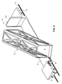
- the railway freight wagon according to the invention shown in FIG. 1 1 has a carriage frame 3 supported on bogies 2.
- a bridge 5 is fitted, which is equipped with a carriageway 6 is.
- a road vehicle, in particular a truck, can drive onto this lane 6 7 can be turned off, as will be described later.
- the bridge 5 is in the transport position in the longitudinal direction of the rail freight wagon aligned and lies on the carriage frame 3.
- On the carriage frame 3 are 5 locking mechanisms in the corner areas of the bridge arranged with which the bridge 5 locks on the carriage frame 3 can be, as will be described in detail later.
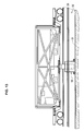
- the bridge 5 points in the form of a box closed at the top, the side surfaces being truss-shaped are trained. This results in an optimal supporting structure, so that the bottom of the bridge, which forms the carriageway 6, has a relatively low overall height can have, while still ensuring an optimal load capacity becomes.
- Walls 41 can also be arranged on the carriage frame 3, which practically close the front of the bridge 5 in the transport position, what can influence the flow conditions of the airstream, in particular with empty rail freight wagons.
- the middle area of the carriage frame 3 does not have to be dimensioned that the weight of bridge 5 and the load of bridge 5 is complete could wear.
- the overall height can also be kept low here, whereby the roadway 6 can be set as low as possible, which means that the trucks 7 transported by these rail freight cars 1 can have a higher corner height.
- the loaded or unloaded bridge 5 is then again in the longitudinal direction of the freight car 1 can be pivoted back, the bridge 5 is then lifted Rotating element 9 lowered again on the carriage frame 3, in this way assumed transport position with the carriage frame 3 via the locking mechanisms 8 locked, the lifting and rotating element can then by the position supported on the track 4 can be raised.
- the rail freight wagon 1 is then ready to leave.
- rail freight cars can be coupled together become and form a train.
- the rail freight wagons 1 can then, each individually, loaded or unloaded.
- FIGS. 6a to 6c show the locking mechanisms 8, with which the bridge 5 are attached to the carriage frame 3.
- a pair of toggle levers 12, 13 is actuated by a hydraulic cylinder 14.
- the a toggle lever 12 is here about an axis 15 fastened to the carriage frame 3 pivotable.
- the other toggle lever is articulated on a pivot lever 16 hitched.
- One arm of this pivot lever 16 is with a cam 17th provided, which can be engaged in a corresponding recess 18 on the bridge is.
- a pull rod 19 is articulated on the other arm of the pivot lever 16, which is connected to a slide latch 20, which on the underside of the Bridge 5 can engage in a corresponding further recess 21.
- FIG. 6a shows the locked state of a locking mechanism 8.
- the bridge 5 is clamped down over the cam 17, while through the sliding bolt 20, the bridge 5 against the bogie 2 is pulled. This creates an optimal connection between the bridge 5 and the carriage frame 3 received.
- a Pair of toggle levers 12, 13 is also the security of this locking mechanism 8 guaranteed against unintentional loosening. This is also the effort to operate this locking mechanism relatively low, it could also be used pneumatically or electrically actuated elements become.
- 6c shows the locking mechanism 8 in the unlocked state, 6b, in a spatial representation.
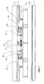
- the lifting and rotating element 9 comprises, as can be seen from FIGS. 7 to 10 is, an upper part 22 which is attached to the underside of the bridge 5.
- articulated connections 23 are rotatably mounted with which the piston rods 24 of hydraulic cylinders 25 articulated are.
- the other ends of the hydraulic cylinders 25 are also articulated with connected to a lower part 26. 7, the lower part 26 is in the raised position Status. In this state, the rail freight wagon can Drive track 4. In this raised state, the lower part 26 is additional still by a pawl mechanism 27, which is at the bottom of the bridge 5 is attached, held.
- Fig. 11 is the raised and pivoted position of the bridge 5 regarding the track 4 can be seen.
- the entry and exit of the bridge 5 is thus located above ramps 28 which can be driven on and in parallel run to track 4.
- ramps 28 are arranged in stations, in which loading and unloading of the rail freight wagons is desired is.
- Fig. 11 is the raised and pivoted position of the bridge 5 shown.
- This bridge 5 can now be lowered by a certain amount until the bottom of the bridge 5 rests on the ramps 28, whereby the required stability for loading and unloading the bridge 5 is given.
- Hydraulic units can for example on the carriage frame 3 in the area Bogies 2 (Fig. 1) may be arranged. These can usually be seen in freight trains existing power grids are fed. Of course the necessary safety devices are also available, for example only allow the lifting and rotating element to be actuated if the rail freight wagon is braked or that the bridge is only lifting can be done when unlocking, etc.
- Flaps 29 can be pivoted at the end regions of the bridge 5 be arranged for loading and unloading on the accessible ramps 28 can be lowered from a raised state, as shown in FIGS. 12a and 12b. With these pivotable flaps 29 level differences can between the carriageway 6 of the swing-out bridge 5 to the corresponding one Ramp 28 can be compensated. These hinged flaps 29 can be actuated hydraulically, in particular in the lowered position they can be blocked, which means that the bridge 5 is supported on the vehicle Ramps 28 is formed, which ensures stability.
- the lifting and Rotating element 9 may be arranged on a carriage 30, which along a Roadway 31, in the area of the track substructure 32 of the track section 4 is attached, is movable.
- the carriage 30 can thus under the bridge 5 of the corresponding rail freight car 1, the upper part 33 the lifting and rotating element 9 is equipped with a coupling element 34, which can engage in a corresponding coupling element 35, which is attached to the underside of the bridge 5, after which the bridge, such as previous embodiment has been described, raised and pivoted can be.
- the carriage 30 is advantageously with positioning elements 36 equipped with the appropriate means 37, the rail freight wagon are attached, can cooperate so that the carriage 30 with respect to the bridge 5 to be lifted and pivoted into the correct position can be brought.
- the carriage 30 is advantageously provided with locking elements 38 equipped, which in correspondingly mounted in the base 32 recordings 39 can be introduced.
- This locking elements 38 can thus Weight of the bridge 5 can be taken up with the appropriate load, the roadway 31 and the wheels of the car 30 are not excessive loaded. They can therefore be dimensioned accordingly. So locked the lifting and rotating device can also absorb tilting moments, which also an asymmetrical load distribution on the bridge is made possible.
Abstract
Description
Die vorliegende Erfindung bezieht sich auf einen Eisenbahngüterwagen für den Transport von Strassenfahrzeugen, insbesondere Lastkraftwagen, umfassend einen auf Drehgestellen abgestützten Wagenrahmen, auf welchem eine Brücke mit einer Fahrbahn für die Aufnahme der Strassenfahrzeuge angeordnet ist, welche um eine im Wesentlichen mittig auf dem Wagenrahmen vorgesehene, senkrecht zur Geleiseebene stehende Achse von einer in Längsrichtung des Güterwagens liegenden Transportposition in eine Be- und Entladeposition ausschwenkbar ist und umgekehrt, in welcher ausgeschwenkten Beund Entladeposition die Strassenfahrzeuge von seitlich neben dem Eisenbahngüterwagen liegenden befahrbaren Rampen auf die Brücke bzw. von der Brücke fahren können.The present invention relates to a rail freight wagon for the transport of road vehicles, especially trucks, comprising a carriage frame supported on bogies, on which a bridge with a roadway for receiving the street vehicles arranged which is provided around a substantially central part of the carriage frame, axis perpendicular to the track plane from a longitudinal direction of the freight car lying in a loading and unloading position can be swung out and vice versa, in which swung out area Unloading the road vehicles from the side next to the rail freight wagon accessible ramps to the bridge or from the bridge can drive.
Derartige Eisenbahngüterwagen sind bekannt. So zeigt beispielsweise die DE-A-37 39 888 ein Schienenfahrzeug zum Transport von Strassenfahrzeugen, bei welchem Ladeflächen durch Radsätze abgestützt sind, und wobei auf der Ladefläche Ladebühnen angeordnet sind, die auf Drehlagern abgestützt sind und seitlich herausschwenkbar sind. Mit dieser Anordnung ist es möglich, dass einzelne Eisenbahngüterwagen beladen und entladen werden können, wobei in der ausgeschwenkten Lage Strassenfahrzeuge von seitlich zum Verladegeleis verlaufenden Rampen auf die Ladebühne fahren können, wonach diese auf die Ladefläche eingeschwenkt wird. Dadurch können in vorteilhafter Weise gleichzeitig mehrere Eisenbahngüterwagen miteinander beladen werden; es ist ohne weiteres auch möglich, aus der Reihe der auf den Eisenbahnzug aufgeladenen Strassenfahrzeugen einzelne an verschiedenen Stationen vom Eisenbahnzug zu entnehmen bzw. neue hinzu zu laden.Such rail freight wagons are known. For example, shows DE-A-37 39 888 a rail vehicle for the transport of road vehicles, at which loading areas are supported by wheel sets, and where loading platforms are arranged on the loading surface, which are supported on pivot bearings are and can be swung out to the side. With this arrangement it is possible that individual rail freight wagons are loaded and unloaded can, with road vehicles from the side in the swiveled-out position can drive ramps to the loading platform to the loading track, after which this is pivoted onto the loading area. This can be advantageous Load several rail freight cars together at the same time become; it is also easily possible from the series on the train charged road vehicles individually at different Remove stations from the train or load new ones.
Bei derartigen Eisenbahngüterwagen soll eine möglichst grosse Ladehöhe erreicht werden können. Dies bedeutet, dass die Ladefläche, auf welche insbesondere Lastkraftwagen zu stehen kommen, möglichst tief gesetzt werden kann, damit auch Tunnels durchfahren werden können.In such rail freight wagons, the greatest possible loading height should be can be achieved. This means that the cargo area on which especially trucks come to a standstill, as low as possible so that tunnels can also be driven through.
Beim oben genannten bekannten Schienenfahrzeug muss die durch die Drehgestelle abgestützte Ladefläche eine grosse Tragkraft aufnehmen können, da das Gewicht durch das zentral angeordnete Drehlager für die Ladebühne aufgenommen werden muss. Demzufolge muss diese Ladefläche eine bestimmte Bauhöhe aufweisen. Zusätzlich muss auch die verschwenkbare Ladebühne entsprechend stabil ausgebildet sein, da auch diese das volle Gewicht der Ladung aufnehmen können muss. Auch die Ladebühne muss somit aus Stabilitätsgründen eine gewisse Bauhöhe aufweisen. Indem die Ladebühne bezüglich der Ladefläche ausschwenkbar sein muss, ergibt sich praktisch die doppelte Bauhöhe für das Untergestell des Schienenfahrzeugs, was sich auf die zuladbare Eckhöhe der Strassenfahrzeuge auswirken kann.In the known rail vehicle mentioned above, the must the bogies supported loading area can take a large load capacity, because the weight is due to the centrally arranged pivot bearing for the loading platform must be included. As a result, this loading area must be one have a certain height. In addition, the swiveling loading platform must also be used be designed to be correspondingly stable, since this also carries the full weight who must be able to take up the load. The loading platform must therefore also be switched off Stability reasons have a certain height. By referring to the loading platform the loading area must be swiveled out, the practically results double height for the undercarriage of the rail vehicle, which is based on the loadable corner height of the road vehicles can affect.
Die Aufgabe der vorliegenden Erfindung besteht nun darin, einen Eisenbahngüterwagen zu schaffen, welcher die Vorteile der Möglichkeit der einzelnen Be- und Entladung gewährleistet, welcher aber andererseits eine geringe Bauhöhe aufweist und somit insbesondere Lastkraftwagen auch mit grosser Eckhöhe auf dem Schienennetz transportieren kann.The object of the present invention is now a railway freight wagon to create the benefits of the opportunity of each Loading and unloading guaranteed, but on the other hand a low one Has overall height and thus especially trucks with large Can transport the corner height on the rail network.
Erfindungsgemäss erfolgt die Lösung dadurch, dass die Brücke mittels eines Hub- und Drehelementes bezüglich des auf den Drehgestellen abgestützten Wagenrahmens anhebbar und verschwenkbar ist und dass das Hubund Drehelement während des Anhebens und Verschwenkens der Brücke auf dem Geleise oder dessen Unterbau abgestützt ist.According to the invention, the solution is achieved by using the bridge a lifting and rotating element with respect to that supported on the bogies Cart frame can be raised and pivoted and that the lifting and Rotating element during the lifting and pivoting of the bridge the track or its substructure is supported.
Durch die Möglichkeit des Anhebens der Brücke bezüglich des Wagenrahmens können Brücke und Wagenrahmen so gestaltet sein, dass bspw. Längsträger ineinander greifen können und somit die Bauhöhe verringert werden kann.Due to the possibility of lifting the bridge in relation to the car frame can bridge and carriage frame be designed so that, for example. Side members can interlock and thus the overall height can be reduced can.
In vorteilhafter Weise wird beim Anheben der Brücke der Unterteil des Hub- und Drehelementes auf dem Geleise abgestützt. Dadurch wird der Wagenrahmen insbesondere im mittleren Bereich entlastet. Die Tragfähigkeit muss nicht so gross sein, was sich wiederum auf die Bauhöhe des Wagenrahmens auswirkt.In an advantageous manner, the lower part becomes when the bridge is raised the lifting and rotating element supported on the track. This will make the Relief of the car frame, particularly in the middle. The load capacity doesn't have to be that big, which in turn depends on the overall height of the trolley frame effect.
Es ist auch möglich, dass im Bereich des Geleiseunterbaus der Geleisestrecke, auf welcher die Eisenbahnwagen be- und entladbar sind, eine Fahrbahn angebracht ist, entlang welcher ein Wagen verfahrbar ist, auf welchem die Hub- und Drehelemente angeordnet sind. Dadurch wird der Vorteil erreicht, dass nicht jeder Eisenbahngüterwagen mit einem hydraulisch betätigbaren Hub- und Drehelement ausgestattet sein muss.It is also possible that in the area of the track substructure the track section, on which the railway wagons can be loaded and unloaded, one Roadway is attached, along which a carriage can be moved, on which the lifting and rotating elements are arranged. This is the advantage achieved that not every rail freight wagon with a hydraulically operated Lifting and rotating element must be equipped.
In vorteilhafter Weise ist hierbei der Oberteil des Hub- und Drehelementes, der bezüglich des Wagens anhebbar und verdrehbar ist, mit einem Kupplungselement ausgestattet, welches in ein korrespondierendes Kupplungselement eingreift, das jeweils an der Unterseite der Brücke angebracht ist, und dass der Unterteil des Hub- und Drehelements am Wagen befestigt ist. Dadurch wird ein sicheres Anheben und Führen der Brücke erreicht.The upper part of the lifting and rotating element is advantageously which can be raised and rotated with respect to the carriage, with a Coupling element equipped, which in a corresponding coupling element intervenes, which is attached to the underside of the bridge, and that the lower part of the lifting and rotating element is attached to the carriage. Thereby safe lifting and guiding of the bridge is achieved.
In vorteilhafter Weise sind am Wagen und am jeweiligen Eisenbahnwagen Positioniermittel angebracht, mittels welcher der Wagen bezüglich des entsprechenden Eisenbahnwagens in Position bringbar ist. Dadurch wird eine schnelle Arbeitsweise erreicht, die Ankupplung des Oberteils des Hub- und Drehelements an der Brücke kann schnell ausgeführt werden.Advantageously, are on the car and the respective railroad car Positioning means attached by means of which the carriage with respect to the corresponding railway carriage can be brought into position. This will make one achieved fast operation, the coupling of the upper part of the lifting and Rotating element on the bridge can be carried out quickly.
Eine weitere vorteilhafte Ausgestaltung dieser Ausführungsform besteht darin, dass der Wagen mit Verriegelungselementen ausgestattet ist, welche in entsprechend im Unterbau angebrachten Aufnahmen einführbar sind. Durch diese Verriegelungselemente wird erreicht, dass das Hub- und Drehelement fest im Unterbau verankert ist, die erforderliche Stabilität der Brücke zu Be- und Entladen wird erreicht.Another advantageous embodiment of this embodiment exists in that the car is equipped with locking elements, which can be inserted in receptacles fitted in the base. These locking elements ensure that the lifting and rotating element is firmly anchored in the substructure, the required stability of the bridge Loading and unloading is achieved.
In vorteilhafter Weise sind die Hubmittel aus Hydraulikzylindern gebildet, die jeweils paarweise und schräg gegeneinander geneigt angeordnet sind und miteinander zusammenwirken, so dass sowohl die Hubbewegung wie auch die Schwenkbewegung durch steuerbare Betätigungen dieser Hydraulikzylinder ausführbar sind. Mit dieser Anordnung können in einfacher Weise sowohl die Hub- als auch die Drehbewegung ausgeführt werden; es ist zudem nicht erforderlich, dass zusätzliche Führungsmittel zur Führung der Brücke bezüglich des Wagenrahmens angebracht werden müssen. The lifting means are advantageously formed from hydraulic cylinders, each arranged in pairs and at an angle to each other are and interact with each other, so that both the lifting movement as also the pivoting movement through controllable actuations of these hydraulic cylinders are executable. With this arrangement, both the lifting as well as the rotating movement are carried out; it is also does not require additional guide means to guide the bridge with respect of the carriage frame must be attached.
In vorteilhafter Weise ist die Brücke in der Transportposition mit dem Wagenrahmen fest verriegelbar, wobei die Verriegelung der Brücke mit dem Wagenrahmen über hydraulisch, pneumatisch oder elektrisch betätigbare Hebeleinrichtungen erfolgen kann, die jeweils in den Eckbereichen der Brücke am Wagenrahmen angebracht sind. Dadurch wird erreicht, dass die Brücke für den Eisenbahngüterwagen zusätzlich als integriertes, Last aufnehmendes Element dient.The bridge is advantageously in the transport position with the Trolley frame lockable, the locking of the bridge with the Cart frame using hydraulically, pneumatically or electrically operated lever devices can be done, each in the corner areas of the bridge on Carriage frames are attached. This ensures that the bridge for the Railway freight wagons additionally as an integrated, load-bearing element serves.
Eine weitere vorteilhafte Ausgestaltung der Erfindung besteht darin, dass die Brücke die Form eines oben geschlossenen Kastens aufweist, dessen Frontseiten offen sind. Durch die Kastenbauweise der Brücke kann das die Fahrbahn bildende Bodenteil mit geringerer Bauhöhe aufgebaut sein, da die Tragkräfte auch durch die Form des Kastens aufgenommen werden können.Another advantageous embodiment of the invention consists in that the bridge is in the form of a box closed at the top, the Fronts are open. Due to the box construction of the bridge that can Roadway-forming floor part with a lower overall height can be built, since the Load capacities can also be absorbed by the shape of the box.
In vorteilhafter Weise sind an den Endbereichen der Fahrbahn der Brücke schwenkbar Klappen angeordnet, die zum Be- und Entladen auf die befahrbaren Rampen von einem angehobenen Zustand absenkbar sind. Dadurch können Niveauunterschiede zwischen der Fahrbahn der Brücke und der jeweiligen Rampe ausgeglichen werden.Advantageously, the Bridge pivotable flaps arranged for loading and unloading on the accessible ramps can be lowered from a raised state. Thereby can level differences between the lane of the bridge and the respective ramp can be compensated.
Hierbei sind die Klappen in vorteilhafter Weise hydraulisch betätigbar und insbesondere in der abgesenkten Position blockierbar, wodurch eine Abstützung für die Brücke auf den befahrbaren Rampen gebildet wird. Dies erhöht die Stabilität der Einrichtung während des Be- und Entladens.Here, the flaps can be operated hydraulically in an advantageous manner and in particular can be blocked in the lowered position, thereby providing support is formed for the bridge on the accessible ramps. This increases the stability of the device during loading and unloading.
Ausführungsformen der vorliegenden Erfindung werden nachfolgend anhand der beiliegenden Zeichnung beispielhaft näher erläutert.Embodiments of the present invention are as follows explained in more detail by way of example with reference to the accompanying drawing.
Es zeigt
Der in Fig. 1 dargestellte, erfindungsgemässe Eisenbahngüterwagen
1 weist einen auf Drehgestellen 2 abgestützten Wagenrahmen 3 auf. Der zwischen
den Drehgestellen liegende mittlere Bereich des Wagenrahmens 3 liegt
möglichst tief über den Geleisen 4. Auf diesen mittleren Bereich des Wagenrahmens
3 ist eine Brücke 5 aufgesetzt, die mit einer Fahrbahn 6 ausgestattet
ist. Auf diese Fahrbahn 6 kann ein Strassenfahrzeug, insbesondere ein Lastkraftwagen
7 abgestellt werden, wie später noch beschrieben wird.The railway freight wagon according to the invention shown in FIG. 1
1 has a
Die Brücke 5 ist in Transportposition in Längsrichtung des Eisenbahngüterwagens
ausgerichtet und liegt auf dem Wagenrahmen 3 auf. Am Wagenrahmen
3 sind in den Eckbereichen der Brücke 5 Verriegelungsmechanismen
angeordnet, mit welchen die Brücke 5 auf dem Wagenrahmen 3 verriegelt
werden kann, wie später noch im Detail beschrieben wird. Die Brücke 5 weist
die Form eines oben geschlossenen Kastens auf, wobei die Seitenflächen fachwerkförmig
ausgebildet sind. Dies ergibt eine optimale Tragkonstruktion, so
dass der Boden der Brücke, der die Fahrbahn 6 bildet, eine relativ geringe Bauhöhe
aufweisen kann, wobei trotzdem eine optimale Tragfähigkeit gewährleistet
wird.The
Am Wagenrahmen 3 können ferner Wände 41 angeordnet sein, welche
die Frontseiten der Brücke 5 in der Transportposition praktisch verschliessen,
was die Strömungsverhältnisse des Fahrtwindes beeinflussen kann, insbesondere
bei unbeladenem Eisenbahngüterwagen.
Da die Brücke 5 insbesondere mit deren Endbereichen auf den Wagenrahmen
3 zur Auflage kommen und in diesen Bereich durch die Verriegelungsmechanismen
8 auch praktisch fest mit dem Wagenrahmen 3 verbunden
ist, muss der mittlere Bereich des Wagenrahmens 3 nicht so dimensioniert werden,
dass er das Gewicht der Brücke 5 und der Ladung der Brücke 5 vollständig
tragen könnte. Dadurch kann auch hier die Bauhöhe gering gehalten werden,
wodurch die Fahrbahn 6 möglichst tief gesetzt werden kann, was bedeutet,
dass die Lastkraftwagen 7, die durch diese Eisenbahngüterwagen 1 transportiert
werden, eine höhere Eckhöhe aufweisen können.Since the
An der Unterseite der Brücke 5 ist im mittleren Bereich ein Hub- und
Drehelement 9 angebracht. Im angehobenen Zustand befindet sich der Unterteil
10 dieses Hub- und Drehelementes 9 oberhalb der Geleiseebene 11.On the underside of the
Wie aus Fig. 2 ersichtlich ist, lässt sich, wenn der Eisenbahngüterwagen
1 sich an der Stelle befindet, wo dieser be- und entladen werden kann,
der Unterteil 10 des Hub- und Drehelementes 9 absenken, bis sich der Unterteil
10 auf der Geleiseebene 11 abstützt. Die Verriegelungsmechanismen 8 können
dann gelöst werden, wie in Fig. 2 dargestellt ist. Die Brücke 5 liegt nun frei auf
dem Wagenrahmen 3, zusätzlich abgestützt durch das Hub- und Drehelement 9
auf dem Geleise 4. As can be seen from Fig. 2, when the rail freight wagon
1 is where it can be loaded and unloaded,
lower the
Durch weiteres Betätigen des Hub- und Drehelementes 9 wird nun
die Brücke 5 angehoben, abgestützt durch den Unterteil 10 des Hub- und Drehelementes
9 auf dem Geleise 4, wie dies in Fig. 3 dargestellt ist. In dieser hier
dargestellten Position stützt sich die Brücke 5 nur noch auf dem Hub- und
Drehelement 9 und somit auf dem Geleise 4 ab.By further actuation of the lifting and
In dieser angehobenen Lage kann die Brücke 5 über das Hub- und
Drehelement 9, das auf dem Geleise 4 abgestützt ist, um eine senkrecht zur
Geleiseebene 11 stehende, durch das Hub- und Drehelement 9 gehende Achse
verschwenkt werden, wie dies aus den Fig. 4 und 5 entnehmbar ist. Insbesondere
in Fig. 5 ist ersichtlich, wie von parallel zum Geleise 4, auf dem sich der zu
be- bzw. entladende Eisenbahngüterwagen befindet, angebrachte, nicht dargestellte
Rampen die Strassenfahrzeuge auf die ausgeschwenkte Brücke 5 fahren
können bzw. von dieser Brücke 5 wegfahren können,In this raised position, the
Die be- bzw. entladene Brücke 5 ist dann wieder in die Längsrichtung
des Güterwagens 1 zurückschwenkbar, die Brücke 5 wird dann durch das Hubund
Drehelement 9 wieder auf den Wagenrahmen 3 abgesenkt, in dieser so
eingenommenen Transportposition mit dem Wagenrahmen 3 über die Verriegelungsmechanismen
8 verriegelt, das Hub- und Drehelement kann danach von
der auf dem Geleise 4 abgestützten Lage angehoben werden. Der Eisenbahngüterwagen
1 ist dann zur Wegfahrt bereit.The loaded or unloaded
Selbstverständlich können mehrere Eisenbahngüterwagen zusammengekoppelt werden und einen Zug bilden. Die Eisenbahngüterwagen 1 können dann, jeder für sich allein, beladen bzw. entladen werden.Of course, several rail freight cars can be coupled together become and form a train. The rail freight wagons 1 can then, each individually, loaded or unloaded.
Es wäre auch denkbar, dass die Endbereiche der Wagenrahmen 3
zweier benachbarter Eisenbahngüterwagen 1 in bekannter Weise lediglich
durch ein Drehgestell abgestützt werden.It would also be conceivable that the end regions of the
Aus den Fig. 6a bis 6c sind die Verriegelungsmechanismen 8 ersichtlich,
mit welchen die Brücke 5 am Wagenrahmen 3 befestigt werden. Hierbei
wird ein Kniehebelpaar 12, 13 durch einen Hydraulikzylinder 14 betätigt. Der
eine Kniehebel 12 ist hierbei um eine am Wagenrahmen 3 befestigte Achse 15
schwenkbar. Der andere Kniehebel ist an einem Schwenkhebel 16 gelenkig
angekuppelt. Der eine Arm dieses Schwenkhebels 16 ist mit einem Nocken 17
versehen, der in eine entsprechende Aussparung 18 an der Brücke eingreifbar
ist. Am anderen Arm des Schwenkhebels 16 ist eine Zugstange 19 angelenkt,
die mit einem Schieberiegel 20 verbunden ist, welcher auf der Unterseite der
Brücke 5 in eine entsprechende weitere Aussparung 21 eingreifen kann.6a to 6c show the locking
Fig. 6a zeigt den verriegelten Zustand eines Verriegelungsmechanismus
8. Hierbei wird die Brücke 5 über den Nocken 17 nach unten verspannt,
während durch den Schieberiegel 20 die Brücke 5 gegen das Drehgestell 2 hin
gezogen wird. Dadurch wird eine optimale Verbindung zwischen der Brücke 5
und dem Wagenrahmen 3 erhalten. Durch die Verwendung eines
Kniehebelpaares 12, 13 ist auch die Sicherheit dieses Verriegelungsmechanismus
8 gegen unbeabsichtigtes Lösen gewährleistet. Damit ist auch der Kraftaufwand
zur Betätigung dieses Verriegelungsmechanismus relativ gering, es
könnten auch pneumatisch oder elektrisch betätigbare Elemente verwendet
werden.6a shows the locked state of a
Fig. 6b zeigt den Verriegelungsmechanismus 8 im entriegelten Zustand,
die Brücke 5 kann in diesem Zustand, wie vorgängig beschrieben wurde,
vom Wagenrahmen 3 angehoben werden.6b shows the
Fig. 6c zeigt den Verriegelungsmechanismus 8 im entriegelten Zustand,
gemäss Fig. 6b, in räumlicher Darstellung.6c shows the
Das Hub- und Drehelement 9 umfasst, wie aus den Fig. 7 bis 10 ersichtlich
ist, einen Oberteil 22, der an der Unterseite der Brücke 5 befestigt ist.
An diesem Unterteil 22 sind Gelenkverbindungen 23 drehbar angebracht, mit
welchen die Kolbenstangen 24 von Hydraulikzylindern 25 gelenkig verbunden
sind. Die anderen Enden der Hydraulikzylinder 25 sind ebenfalls gelenkig mit
einem Unterteil 26 verbunden. In Fig. 7 befindet sich der Unterteil 26 im angehobenen
Zustand. In diesem Zustand kann der Eisenbahngüterwagen auf dem
Geleise 4 fahren. In diesem angehobenen Zustand ist der Unterteil 26 zusätzlich
noch durch einen Klinkenmechanismus 27, der an der Unterseite der Brücke
5 befestigt ist, gehalten. The lifting and
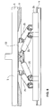
Nach dem Entriegeln des Klinkenmechanismus 27 kann durch Betätigen
der Hydraulikzylinder 25 der Unterteil 26 abgesenkt werden, wie dies in
Fig. 8 dargestellt ist, bis er auf dem Geleise 4 zur Auflage kommt. Zwischen
Oberteil 22 und Unterteil 26 sind im vorliegenden Ausführungsbeispiel acht
Hydraulikzylinder 25 angeordnet, wovon jeweils zwei ein Paar bilden, die
schräg gegeneinander angeordnet sind. Wenn alle Hydraulikzylinder 25 gleichzeitig
betätigt werden, wird der Unterteil 26 bezüglich des Oberteils 22 abgesenkt
bzw. angehoben.After unlocking the
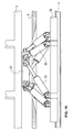
Wenn die Position des Unterteils 26, wie sie in Fig. 8 dargestellt ist,
erreicht ist, d.h., wenn der Unterteil 26 sich auf dem Geleise 4 abstützt, können,
wie vorgängig bereits beschrieben worden ist, die Verriegelungsmechanismen
zwischen Brücke 5 und Wagenrahmen 3 gelöst werden. Die Hydraulikzylinder
25 können weiter gleichzeitig betätigt werden, die Brücke 5 wird dann bezüglich
des Geleises 4 und demzufolge bezüglich des Wagenrahmens 3 angehoben,
wie in Fig. 9 dargestellt ist. Das Gewicht der Brücke 5 lastet somit vollständig
auf dem Geleise 4.If the position of the
Im angehobenen Zustand der Brücke 5, wie dies in Fig. 9 dargestellt
ist, können jeweils die paarweise angeordneten Hydraulikzylinder unterschiedlich
betätigt werden. Man erhält somit ein Verschwenken des Oberteils 22 und
demzufolge der Brücke 5 bezüglich des Unterteils 26 und demzufolge des Geleises
4, wie dies in Fig. 10 dargestellt ist. Somit lässt sich das Anheben bzw.
Absenken der Brücke 5 und das Verschwenken der Brücke 5 durch entsprechendes
gesteuertes Betätigen der Hydraulikzylinder 25 erreichen, ohne dass
zusätzliche Führungselemente erforderlich sind.In the raised state of the
In Fig. 11 ist die angehobene und ausgeschwenkte Lage der Brücke
5 bezüglich des Geleises 4 ersichtlich. Das Einfahr- und Ausfahrende der Brücke
5 befindet sich somit oberhalb von Rampen 28, die befahrbar sind und parallel
zum Geleise 4 verlaufen. Derartige Rampen 28 sind in Stationen angeordnet,
in welchen ein Be- und Entladen der Eisenbahngüterwagen erwünscht
ist. In Fig. 11 is the raised and pivoted position of the
In Fig. 11 ist die angehobene und ausgeschwenkte Lage der Brücke
5 dargestellt. Diese Brücke 5 kann nun um ein bestimmtes Mass abgesenkt
werden, bis die Unterseite der Brücke 5 auf den Rampen 28 aufliegt, wodurch
die erforderliche Stabilität zum Be- und Entladen der Brücke 5 gegeben ist.In Fig. 11 is the raised and pivoted position of the
Die zur Betätigung der Hydraulikzylinder 25 des Hub- und Drehelementes
9 und aller weiteren hydraulisch betätigbaren Elemente erforderlichen
Hydraulikaggregate können beispielsweise am Wagenrahmen 3 im Bereich der
Drehgestelle 2 (Fig. 1) angeordnet sein. Diese können von in Güterzügen üblicherweise
vorhandenen Stromnetzen gespiesen werden. Selbstverständlich
sind auch die erforderlichen Sicherheitseinrichtungen vorhanden, welche beispielsweise
nur erlauben, dass das Hub- und Drehelement betätigbar ist, wenn
der Eisenbahngüterwagen gebremst ist oder dass ein Anheben der Brücke erst
beim Entriegeln erfolgen kann, usw.To actuate the
An den Endbereichen der Brücke 5 können schwenkbar Klappen 29
angeordnet sein, die zum Be- und Entladen auf die befahrbaren Rampen 28
von einem angehobenen Zustand absenkbar sind, wie dies in den Figuren 12a
und 12b dargestellt ist. Mit diesen schwenkbaren Klappen 29 können Niveauunterschiede
zwischen der Fahrbahn 6 der ausgeschwenkten Brücke 5 zur entsprechenden
Rampe 28 ausgeglichen werden. Diese schwenkbaren Klappen
29 sind hydraulisch betätigbar, insbesondere in der abgesenkten Position sind
sie blockierbar, wodurch eine Abstützung für die Brücke 5 auf den befahrbaren
Rampen 28 gebildet wird, wodurch die Stabilität gewährleistet ist.
Wie aus den Figuren 13 und 14 entnehmbar ist, kann das Hub- und
Drehelement 9 auf einem Wagen 30 angeordnet sein, welcher entlang einer
Fahrbahn 31, die im Bereich des Geleiseunterbaus 32 der Geleisestrecke 4
angebracht ist, verfahrbar ist. Der Wagen 30 kann somit unter die Brücke 5 des
entsprechenden Eisenbahngüterwagens 1 verfahren werden, der Oberteil 33
des Hub- und Drehelementes 9 ist mit einem Kupplungselement 34 ausgestattet,
welches in ein korrespondierendes Kupplungselement 35 eingreifen kann,
das an der Unterseite der Brücke 5 angebracht ist, wonach die Brücke, wie zum
vorgängigen Ausführungsbeispiel beschrieben worden ist, angehoben und verschwenkt
werden kann. Der Wagen 30 ist in vorteilhafter Weise mit Positionierelementen
36 ausgestattet, die mit entsprechenden Mitteln 37, die am Eisenbahngüterwagen
angebracht sind, zusammenwirken können, so dass der Wagen
30 bezüglich der anzuhebenden und zu verschwenkenden Brücke 5 in die
richtige Position gebracht werden kann.As can be seen from FIGS. 13 and 14, the lifting and
In vorteilhafter Weise ist der Wagen 30 mit Verriegelungselementen
38 ausgestattet, welche in entsprechend im Unterbau 32 angebrachte Aufnahmen
39 einführbar sind. Durch diese Verriegelungselemente 38 kann somit das
Gewicht der Brücke 5 mit der entsprechenden Beladung aufgenommen werden,
die Fahrbahn 31 und die Räder des Wagens 30 werden damit nicht übermässig
belastet. Sie können somit entsprechend dimensioniert sein. Derart verriegelt
kann die Hub-Dreh-Einrichtung auch Kippmomente aufnehmen, wodurch auch
eine asymmetrische Lastverteilung auf der Brücke ermöglicht wird.The
Aus Fig. 15 ist ersichtlich, dass das Kupplungselement 34, das am
Oberteil 33 des Wagens 30 befestigt ist, im in das entsprechende Kupplungselement
35 der Brücke 5 eingesetztem Zustand ebenfalls durch entsprechend
angebrachte Bolzen 40 verriegelbar ist. Das Hub- und Drehelement 9, das auf
dem Wagen 30 angeordnet ist, kann gleich aufgebaut sein, wie beim vorgängig
beschriebenen Ausführungsbeispiel, es sind aber auch andere Hub- und
Schwenkmittel denkbar, die dem Fachmann bekannt sind.From Fig. 15 it can be seen that the
Mit diesem Wagen 30 kann die jeweilige Brücke 5 des entsprechenden
Eisenbahngüterwagens 1 wie zum vorgängigen Ausführungsbeispiel beschrieben
worden ist, angehoben und verschwenkt werden, wie in Fig. 16 dargestellt
ist. Es ist somit nicht erforderlich, dass jeder Eisenbahngüterwagen mit
einem Hub- und Drehelement 9 ausgestattet ist mit den dazu erforderlichen
Hydraulikaggregaten. Ein derartiger Wagen 30 kann beispielsweise für einen
ganzen Zug verwendet werden, indem er von einem Eisenbahngüterwagen
zum anderen fährt. Es ist auch denkbar, dass über die Länge eines ganzen Zuges
weitere derartige Wagen 30 eingesetzt werden können. Diese sind mit der
entsprechenden Stromzuführung und den jeweils erforderlichen Hydraulikaggregaten
ausgestattet.With this
Claims (12)
Priority Applications (1)
| Application Number | Priority Date | Filing Date | Title |
|---|---|---|---|
| EP02405239A EP1348603A1 (en) | 2002-03-26 | 2002-03-26 | Rail wagon for transporting road vehicles |
Applications Claiming Priority (1)
| Application Number | Priority Date | Filing Date | Title |
|---|---|---|---|
| EP02405239A EP1348603A1 (en) | 2002-03-26 | 2002-03-26 | Rail wagon for transporting road vehicles |
Publications (1)
| Publication Number | Publication Date |
|---|---|
| EP1348603A1 true EP1348603A1 (en) | 2003-10-01 |
Family
ID=27798960
Family Applications (1)
| Application Number | Title | Priority Date | Filing Date |
|---|---|---|---|
| EP02405239A Withdrawn EP1348603A1 (en) | 2002-03-26 | 2002-03-26 | Rail wagon for transporting road vehicles |
Country Status (1)
| Country | Link |
|---|---|
| EP (1) | EP1348603A1 (en) |
Cited By (9)
| Publication number | Priority date | Publication date | Assignee | Title |
|---|---|---|---|---|
| WO2004062976A1 (en) * | 2003-01-16 | 2004-07-29 | Frenzel Bau Gmbh & Co. Kg | Method and device for transferring goods between the road and railroad |
| EP1634792A3 (en) * | 2004-07-26 | 2006-03-22 | Cholerton Limited | A rail terminal located pop-up mechanism for the rotating lowfloor platforms of road/rail intermodal wagon |
| EP1757508A3 (en) * | 2005-01-20 | 2007-03-14 | Grigorij Korsakov | Railway wagon for the transportation of bulk loads, especially road vehicles |
| NL2006249C2 (en) * | 2011-02-18 | 2012-08-21 | Sommeren | Transshipment system including a lift unit for moving a well car floor of a railway well car. |
| EP3299244A1 (en) * | 2016-09-21 | 2018-03-28 | Paul Bunzel | Track-bound freight wagon for transporting stand-alone transport vehicles |
| WO2020084081A1 (en) * | 2018-10-24 | 2020-04-30 | Helrom Limited | Railway wagon for transportation of semitrailers and the like |
| CN113636082A (en) * | 2021-07-08 | 2021-11-12 | 凌云(宜昌)航空装备工程有限公司 | Cargo loading and unloading bridge for self-propelled equipment of conveyor |
| RU2790995C2 (en) * | 2018-10-24 | 2023-03-01 | ХЕЛРОМ ГмбХ | Railway car for transportation of semitrailers and vehicle similar to semitrailer |
| WO2023028275A1 (en) * | 2021-08-25 | 2023-03-02 | Gearhart Jacob Keller | Rail based mobility systems and methods of installation and use |
Citations (5)
| Publication number | Priority date | Publication date | Assignee | Title |
|---|---|---|---|---|
| FR1463056A (en) * | 1965-09-24 | 1966-12-23 | Side loading and unloading wagon by translation | |
| DE1243714B (en) * | 1960-12-10 | 1967-07-06 | Maschf Augsburg Nuernberg Ag | Lifting and lowering device for loading area parts of a rail vehicle |
| DE3003616A1 (en) * | 1980-02-01 | 1981-08-06 | Rudolf 2102 Hamburg Behrens | Railway wagon carrying road vehicle - is loaded by swinging round load deck to mate with ramp at end |
| EP0463283A1 (en) * | 1990-06-25 | 1992-01-02 | Immobiliare Varcas S.P.A. | A rail car for the carriage and transportation of commercial road vehicles |
| DE19546300C1 (en) * | 1995-10-04 | 1997-04-30 | Matthias Gradenwitz | Loading and unloading freight vehicles from a railway train |
-
2002
- 2002-03-26 EP EP02405239A patent/EP1348603A1/en not_active Withdrawn
Patent Citations (5)
| Publication number | Priority date | Publication date | Assignee | Title |
|---|---|---|---|---|
| DE1243714B (en) * | 1960-12-10 | 1967-07-06 | Maschf Augsburg Nuernberg Ag | Lifting and lowering device for loading area parts of a rail vehicle |
| FR1463056A (en) * | 1965-09-24 | 1966-12-23 | Side loading and unloading wagon by translation | |
| DE3003616A1 (en) * | 1980-02-01 | 1981-08-06 | Rudolf 2102 Hamburg Behrens | Railway wagon carrying road vehicle - is loaded by swinging round load deck to mate with ramp at end |
| EP0463283A1 (en) * | 1990-06-25 | 1992-01-02 | Immobiliare Varcas S.P.A. | A rail car for the carriage and transportation of commercial road vehicles |
| DE19546300C1 (en) * | 1995-10-04 | 1997-04-30 | Matthias Gradenwitz | Loading and unloading freight vehicles from a railway train |
Cited By (12)
| Publication number | Priority date | Publication date | Assignee | Title |
|---|---|---|---|---|
| WO2004062976A1 (en) * | 2003-01-16 | 2004-07-29 | Frenzel Bau Gmbh & Co. Kg | Method and device for transferring goods between the road and railroad |
| EP1634792A3 (en) * | 2004-07-26 | 2006-03-22 | Cholerton Limited | A rail terminal located pop-up mechanism for the rotating lowfloor platforms of road/rail intermodal wagon |
| EP1757508A3 (en) * | 2005-01-20 | 2007-03-14 | Grigorij Korsakov | Railway wagon for the transportation of bulk loads, especially road vehicles |
| NL2006249C2 (en) * | 2011-02-18 | 2012-08-21 | Sommeren | Transshipment system including a lift unit for moving a well car floor of a railway well car. |
| EP2489569A1 (en) * | 2011-02-18 | 2012-08-22 | Johannes Gerardus Maria Van Sommeren | Transshipment system including a lift unit for moving a well car floor of a railway well car |
| EP3299244A1 (en) * | 2016-09-21 | 2018-03-28 | Paul Bunzel | Track-bound freight wagon for transporting stand-alone transport vehicles |
| WO2020084081A1 (en) * | 2018-10-24 | 2020-04-30 | Helrom Limited | Railway wagon for transportation of semitrailers and the like |
| EP4056445A1 (en) * | 2018-10-24 | 2022-09-14 | Helrom GmbH | Railway wagon for transportation of semitrailers and the like |
| RU2790995C2 (en) * | 2018-10-24 | 2023-03-01 | ХЕЛРОМ ГмбХ | Railway car for transportation of semitrailers and vehicle similar to semitrailer |
| CN113636082A (en) * | 2021-07-08 | 2021-11-12 | 凌云(宜昌)航空装备工程有限公司 | Cargo loading and unloading bridge for self-propelled equipment of conveyor |
| CN113636082B (en) * | 2021-07-08 | 2024-03-29 | 凌云(宜昌)航空装备工程有限公司 | Loading and unloading bridge for self-assembled conveyor |
| WO2023028275A1 (en) * | 2021-08-25 | 2023-03-02 | Gearhart Jacob Keller | Rail based mobility systems and methods of installation and use |
Similar Documents
| Publication | Publication Date | Title |
|---|---|---|
| DE102006012208B4 (en) | wagon | |
| EP2228278B1 (en) | Wagon | |
| DE2029636A1 (en) | Transfer device | |
| EP1519868B1 (en) | Method for the loading and unloading of railway wagons and device, wagon chassis and wagon attachment for carrying out said method | |
| DE1129521B (en) | Railway wagons for the transport of articulated lorries | |
| EP1348603A1 (en) | Rail wagon for transporting road vehicles | |
| DE4332266C2 (en) | Freight wagons to form a rail-bound freight train for combined rail / road freight transport | |
| EP0064053A1 (en) | Wagon with lowered platform for the railway transport of motor vehicles and giant containers | |
| DE202011100028U1 (en) | Trailer for a trailer train | |
| AT403708B (en) | TRACK CONSTRUCTION MACHINE | |
| DE60117834T2 (en) | SUPPORT STRUCTURE FOR THE SWIVEL MOVEMENT OF A ROTATABLE STRUCTURE OF A WAGON OF THE COMBINED RAIL / ROAD TRANSPORT | |
| EP3299244B1 (en) | Track-bound freight wagon for transporting stand-alone transport vehicles | |
| DE1012949B (en) | Device for adapting the jockey wheel racks of trailers to be used for road traffic in connection with articulated lorries to the receiving track of carrier vehicles traveling on rails for rail transport | |
| DE60026790T2 (en) | Motor vehicle with a load handling system | |
| DE10113074A1 (en) | Device for bridging level differences when entering and leaving vehicles has horizontal platform which in relation to level of floor of vehicle is movable upwards to higher level and also downwards to lower level | |
| DE3728565C2 (en) | Innenlader transport system | |
| DE1985583U (en) | RAILWAY CARS FOR LOADING CONTAINERS. | |
| DE102021104173B4 (en) | Railway carriage with a swing bridge | |
| DE2902354A1 (en) | DARE | |
| EP0005517B1 (en) | Supporting jack with securing means for transporting two-wheel trailers by railway | |
| EP0538648B1 (en) | Carrying wagon for combined road-rail transport | |
| DE102011100145A1 (en) | Trailer for goods wagon used in automotive component production line, has releasable locking unit that is arranged in supporting frame for locking load received in supporting frame | |
| DE957449C (en) | Three-axle motor vehicle for transporting railroad cars on ordinary roads | |
| DE1215740B (en) | Transport trolleys, in particular transport rail vehicles, with two loading areas one above the other | |
| DE202021100870U1 (en) | Railway carriage with a swing bridge |
Legal Events
| Date | Code | Title | Description |
|---|---|---|---|
| PUAI | Public reference made under article 153(3) epc to a published international application that has entered the european phase |
Free format text: ORIGINAL CODE: 0009012 |
|
| AK | Designated contracting states |
Kind code of ref document: A1 Designated state(s): AT BE CH CY DE DK ES FI FR GB GR IE IT LI LU MC NL PT SE TR |
|
| AX | Request for extension of the european patent |
Extension state: AL LT LV MK RO SI |
|
| 17P | Request for examination filed |
Effective date: 20040115 |
|
| 17Q | First examination report despatched |
Effective date: 20040223 |
|
| AKX | Designation fees paid |
Designated state(s): AT BE CH CY DE DK ES FI FR GB GR IE IT LI LU MC NL PT SE TR |
|
| STAA | Information on the status of an ep patent application or granted ep patent |
Free format text: STATUS: THE APPLICATION IS DEEMED TO BE WITHDRAWN |
|
| 18D | Application deemed to be withdrawn |
Effective date: 20040907 |