EP1348594A1 - Projecteur d'éclairage équipé d'un réflecteur elliptique pivotant et d'une lentille fixe pour la réalisation d'un faisceau de virage - Google Patents
Projecteur d'éclairage équipé d'un réflecteur elliptique pivotant et d'une lentille fixe pour la réalisation d'un faisceau de virage Download PDFInfo
- Publication number
- EP1348594A1 EP1348594A1 EP03290681A EP03290681A EP1348594A1 EP 1348594 A1 EP1348594 A1 EP 1348594A1 EP 03290681 A EP03290681 A EP 03290681A EP 03290681 A EP03290681 A EP 03290681A EP 1348594 A1 EP1348594 A1 EP 1348594A1
- Authority
- EP
- European Patent Office
- Prior art keywords
- reflector
- lens element
- projector
- axis
- optical axis
- Prior art date
- Legal status (The legal status is an assumption and is not a legal conclusion. Google has not performed a legal analysis and makes no representation as to the accuracy of the status listed.)
- Granted
Links
- 230000003287 optical effect Effects 0.000 claims abstract description 48
- 230000001105 regulatory effect Effects 0.000 claims description 5
- 230000004048 modification Effects 0.000 claims description 3
- 238000012986 modification Methods 0.000 claims description 3
- 238000013459 approach Methods 0.000 claims 1
- 238000010586 diagram Methods 0.000 description 4
- 230000007423 decrease Effects 0.000 description 3
- 238000004519 manufacturing process Methods 0.000 description 2
- 229920000297 Rayon Polymers 0.000 description 1
- 230000003416 augmentation Effects 0.000 description 1
- 230000033228 biological regulation Effects 0.000 description 1
- 238000005286 illumination Methods 0.000 description 1
- 238000003384 imaging method Methods 0.000 description 1
- 238000000465 moulding Methods 0.000 description 1
- 239000002964 rayon Substances 0.000 description 1
- 238000004088 simulation Methods 0.000 description 1
Images


Classifications
-
- B—PERFORMING OPERATIONS; TRANSPORTING
- B60—VEHICLES IN GENERAL
- B60Q—ARRANGEMENT OF SIGNALLING OR LIGHTING DEVICES, THE MOUNTING OR SUPPORTING THEREOF OR CIRCUITS THEREFOR, FOR VEHICLES IN GENERAL
- B60Q1/00—Arrangement of optical signalling or lighting devices, the mounting or supporting thereof or circuits therefor
- B60Q1/02—Arrangement of optical signalling or lighting devices, the mounting or supporting thereof or circuits therefor the devices being primarily intended to illuminate the way ahead or to illuminate other areas of way or environments
- B60Q1/04—Arrangement of optical signalling or lighting devices, the mounting or supporting thereof or circuits therefor the devices being primarily intended to illuminate the way ahead or to illuminate other areas of way or environments the devices being headlights
- B60Q1/06—Arrangement of optical signalling or lighting devices, the mounting or supporting thereof or circuits therefor the devices being primarily intended to illuminate the way ahead or to illuminate other areas of way or environments the devices being headlights adjustable, e.g. remotely-controlled from inside vehicle
- B60Q1/08—Arrangement of optical signalling or lighting devices, the mounting or supporting thereof or circuits therefor the devices being primarily intended to illuminate the way ahead or to illuminate other areas of way or environments the devices being headlights adjustable, e.g. remotely-controlled from inside vehicle automatically
- B60Q1/12—Arrangement of optical signalling or lighting devices, the mounting or supporting thereof or circuits therefor the devices being primarily intended to illuminate the way ahead or to illuminate other areas of way or environments the devices being headlights adjustable, e.g. remotely-controlled from inside vehicle automatically due to steering position
-
- B—PERFORMING OPERATIONS; TRANSPORTING
- B60—VEHICLES IN GENERAL
- B60Q—ARRANGEMENT OF SIGNALLING OR LIGHTING DEVICES, THE MOUNTING OR SUPPORTING THEREOF OR CIRCUITS THEREFOR, FOR VEHICLES IN GENERAL
- B60Q1/00—Arrangement of optical signalling or lighting devices, the mounting or supporting thereof or circuits therefor
- B60Q1/02—Arrangement of optical signalling or lighting devices, the mounting or supporting thereof or circuits therefor the devices being primarily intended to illuminate the way ahead or to illuminate other areas of way or environments
- B60Q1/04—Arrangement of optical signalling or lighting devices, the mounting or supporting thereof or circuits therefor the devices being primarily intended to illuminate the way ahead or to illuminate other areas of way or environments the devices being headlights
- B60Q1/18—Arrangement of optical signalling or lighting devices, the mounting or supporting thereof or circuits therefor the devices being primarily intended to illuminate the way ahead or to illuminate other areas of way or environments the devices being headlights being additional front lights
-
- F—MECHANICAL ENGINEERING; LIGHTING; HEATING; WEAPONS; BLASTING
- F21—LIGHTING
- F21S—NON-PORTABLE LIGHTING DEVICES; SYSTEMS THEREOF; VEHICLE LIGHTING DEVICES SPECIALLY ADAPTED FOR VEHICLE EXTERIORS
- F21S41/00—Illuminating devices specially adapted for vehicle exteriors, e.g. headlamps
- F21S41/20—Illuminating devices specially adapted for vehicle exteriors, e.g. headlamps characterised by refractors, transparent cover plates, light guides or filters
- F21S41/25—Projection lenses
- F21S41/26—Elongated lenses
-
- F—MECHANICAL ENGINEERING; LIGHTING; HEATING; WEAPONS; BLASTING
- F21—LIGHTING
- F21S—NON-PORTABLE LIGHTING DEVICES; SYSTEMS THEREOF; VEHICLE LIGHTING DEVICES SPECIALLY ADAPTED FOR VEHICLE EXTERIORS
- F21S41/00—Illuminating devices specially adapted for vehicle exteriors, e.g. headlamps
- F21S41/20—Illuminating devices specially adapted for vehicle exteriors, e.g. headlamps characterised by refractors, transparent cover plates, light guides or filters
- F21S41/25—Projection lenses
- F21S41/275—Lens surfaces, e.g. coatings or surface structures
-
- F—MECHANICAL ENGINEERING; LIGHTING; HEATING; WEAPONS; BLASTING
- F21—LIGHTING
- F21S—NON-PORTABLE LIGHTING DEVICES; SYSTEMS THEREOF; VEHICLE LIGHTING DEVICES SPECIALLY ADAPTED FOR VEHICLE EXTERIORS
- F21S41/00—Illuminating devices specially adapted for vehicle exteriors, e.g. headlamps
- F21S41/60—Illuminating devices specially adapted for vehicle exteriors, e.g. headlamps characterised by a variable light distribution
- F21S41/67—Illuminating devices specially adapted for vehicle exteriors, e.g. headlamps characterised by a variable light distribution by acting on reflectors
- F21S41/675—Illuminating devices specially adapted for vehicle exteriors, e.g. headlamps characterised by a variable light distribution by acting on reflectors by moving reflectors
-
- B—PERFORMING OPERATIONS; TRANSPORTING
- B60—VEHICLES IN GENERAL
- B60Q—ARRANGEMENT OF SIGNALLING OR LIGHTING DEVICES, THE MOUNTING OR SUPPORTING THEREOF OR CIRCUITS THEREFOR, FOR VEHICLES IN GENERAL
- B60Q2300/00—Indexing codes for automatically adjustable headlamps or automatically dimmable headlamps
- B60Q2300/10—Indexing codes relating to particular vehicle conditions
- B60Q2300/12—Steering parameters
- B60Q2300/122—Steering angle
-
- B—PERFORMING OPERATIONS; TRANSPORTING
- B60—VEHICLES IN GENERAL
- B60Q—ARRANGEMENT OF SIGNALLING OR LIGHTING DEVICES, THE MOUNTING OR SUPPORTING THEREOF OR CIRCUITS THEREFOR, FOR VEHICLES IN GENERAL
- B60Q2300/00—Indexing codes for automatically adjustable headlamps or automatically dimmable headlamps
- B60Q2300/30—Indexing codes relating to the vehicle environment
- B60Q2300/33—Driving situation
- B60Q2300/334—Driving situation on motorways
Definitions
- the present invention relates to a lighting projector of motor vehicle.
- the present invention relates more particularly to a automotive vehicle headlamp which is designed to make at least one so-called bend lighting beam in view improve lighting when the vehicle is approaching a turn, type comprising an optical system which comprises, arranged from back to front generally along a longitudinal axis horizontal reference, an elliptical type reflector, a light source arranged in the vicinity of a first focus of the reflector, and a converging lens element, of the type in which at least the reflector and the light source are mounted pivoting about a substantially vertical axis, relative to a fixed support of the vehicle, depending on the steering angle of the steering wheels of the vehicle, thereby defining an optical axis movable relative to the longitudinal axis.
- this type of projector has a swivel assembly consisting of a elliptical reflector, a light source, a cover and a converging lens.
- the cornering beam is intended to be combined with a regulatory low beam, or low beam crossing.
- the turning beam produced by the headlamp described previously is not satisfactory because it does not evolve in function of the steering angle.
- the service offered by the cornering headlight resembles a beam of pocket ”which is oriented more or less in the direction of turn.
- the large number of moving parts is also a source of difficulty for the adjustment of parts between them and for the arrangement of the projector in an optical unit of the vehicle.
- the invention aims to remedy these drawbacks.
- the invention proposes a lighting projector of the type described above, characterized in that the element of lens is fixed relative to the support, and in that the element of lens has a so-called lateral part, which is arranged next to it of the longitudinal axis, in an angular sector likely to be swept by the moving optical axis, and which is designed to cause a modification of the turning beam as a function of the angle of bend formed by the movable optical axis with the longitudinal axis.
- the turning beam changes according to the steering angle, so that the cornering beam obtained has a certain continuity with the passing beam, and so that the turning beam has a more homogeneous light distribution, in particular for turning angles between ten and sixty degrees.
- the projector according to the invention makes it possible to reduce the number of moving parts, which reduces the mechanical stresses borne by the projector.
- the lens element comprises a front part adjacent to the lateral part, the optical axis of which is substantially parallel to the longitudinal axis and whose focal plane is located at near the second focus of the reflector, when the reflector occupies its angular position of rest, in which the optical axis mobile is substantially coincident with the longitudinal axis, so that the projector can make at least one beam additional regulatory lighting, for example a beam lighting for highway traffic, when the reflector occupies its rest position.
- the projector according to the invention allows to realize at minus an additional function, which is advantageous, especially in terms of costs and overall dimensions lighting elements fitted to the vehicle. According to other characteristics of the invention:
- a motor vehicle 10 is shown equipped at the front with two lighting optical units, respectively left 12 and right 14.
- Each optical unit 12, 14 here comprises a projector main 16 which is designed to realize a lighting beam regulation of the low beam type Fc, and a headlamp additional 18, which is carried out in accordance with the teaching of the invention, and which is designed to produce in particular a cornering light regulatory beam, which will be called cornering beam Fv.
- the invention will be described applied to the additional projector 18 of the optical lighting unit right 14, it being understood that the elements of the optical unit left 12 are arranged globally symmetrical to those of the right optical unit 14, with respect to a plane of symmetry vertical passing through the A-A axis of the vehicle 10.
- the additional projector 18 is a projector of the bright image reproduction, usually called a projector of the elliptical type.
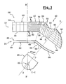
- the optical system of the additional projector 18 comprises therefore, arranged from back to front generally along an axis longitudinal horizontal reference B-B which is parallel to the axis A-A of vehicle 10, an elliptical type reflector 20, a source luminous 22 arranged in the vicinity of a first focus of the reflector 20, cover 24 and a converging lens element 26.
- the reflector 20 has a substantially parabolic horizontal generator and a substantially elliptical vertical generator.
- only the reflector 20 and the light source 22 are pivotally mounted around a substantially vertical axis C-C, with respect to a fixed support (not shown) of the vehicle 10, depending on the steering angle of the steering wheels of the vehicle 10.
- the cover 24 and the lens element 26 are therefore fixed.
- the reflector 20 and the source 22 therefore define an axis moving optic D-D with respect to the longitudinal axis B-B.
- the mobile optical axis D-D is here substantially horizontal and it can be defined for example by the two focal points of the reflector elliptical 20.
- the reflector 20 occupies a position angular of rest in which the movable optical axis D-D is confused with the longitudinal reference axis B-B.
- the mobile optical axis D-D forms with the axis longitudinal reference B-B a so-called turning angle av.
- the shape of the lens element 26 is obtained and optimized by simulations, in particular using of computer tools.
- the lens element 26 with input rear faces 32, 44, 46, 50, that is to say the faces arranged on the side of the light source 22, which are flat.
- the input rear faces 32, 44, 46, 50 could also be any shapes, cylindrical or spherical.
- the front part 28 is designed to allow the additional projector 18 to produce at least one beam additional regulatory lighting, for example a beam lighting for traffic on motorways or beams Fa motorway, when the reflector 20 occupies its position angular rest.
- the optical axis of the front part 28 is parallel to the axis longitudinal reference B-B, and its focal plane is located at in the vicinity of the second focus of the reflector 20, when the reflector 20 occupies its angular position of rest.
- the front part 28 is produced here in the form of a semi-cylindrical convex plane lens, i.e. the part frontal forms a half-cylinder of horizontal and perpendicular axis to the longitudinal axis B-B.
- the reflector 20 When the reflector 20 occupies its rest position, the light rays emitted by the source 22 penetrate into the part front 28 by its flat rear face 32, which is generally orthogonal to the longitudinal axis B-B, and they exit by its face cylindrical convex 34.
- the side part 30 is designed to cause a modification of the turning beam Fv as a function of the angle of bend with the mobile optical axis D-D forming with the axis longitudinal B-B.
- the lateral part 30 must cause a horizontal spread of the turning beam Fv proportional to the turning angle av.
- the lateral end portion 36 here has the shape of a half-lens plano-convex of the spherical type.
- the end portion 36 has a semi-circular edge 42 which is adjacent to the first intermediate portion 38, of so that there is no setback between the surfaces of the end portion 36 and those of the first portion intermediate 38.
- the optical axis E-E of the end portion 36 passes through the plane which is defined by the semicircular edge 42. It corresponds to the optical axis of the complete spherical lens.
- the first intermediate portion 38 generally has the shape of a semi-cylindrical lens, the axis of the cylinder being horizontal and perpendicular to the optical axis E-E of the portion end 36.
- the input rear face 44 of the first portion intermediate 38 is flat and extends the rear inlet face 46 of the end portion 36, to the left considering the figure 3.
- the convex outlet face 48 of the first portion intermediate 38 has a wavy profile, in a horizontal plane, as can be seen in the top view of Figure 3.
- This wavy profile comes from the fact that the convex profile of the first intermediate portion 38, in section through a vertical plane, evolves angularly along the lateral part 30, so that the width of the turning beam Fv increases gradually with increasing angle of turn av from the rest position.
- the wavy profile must also allow a light supply in an area to the right of the cornering beam Fv, for example for a turning angle av of between ten and twenty degrees, and in an area to the left of the cornering beam Fv, for example for a turning angle av of between twenty and thirty degrees.
- the second intermediate portion 40 is here shaped as semi-cylindrical lens, in the extension of the part frontal 28.
- the rear entry face 50 of the second portion intermediate 40 is therefore flat, and it extends the rear face entry 32 of the front part 28, to the right considering Figure 3.
- the profile of the second intermediate portion 40 in section by a vertical plane, evolves angularly along the lateral part 30, so that the width of the turning beam Fv gradually increases with increasing angle of turn forward from the rest position.
- the second intermediate portion 40 is formed of several elementary sections 52 of cylindrical lens which have each an inclined convex outlet face 54, in a plane horizontal, with respect to the exit face 34 of the front part 28.
- each section elementary 52 The inclination of the outlet face 54 of each section elementary 52 is such that this outlet face 54 is substantially orthogonal to the associated turning angle av, say the angle of attack of the moving optical axis D-D on the face inlet 50 of said elementary section 52.
- the first 38 and the second 40 intermediate portions define between them a joint plane 56 which is globally vertical and which contains a determined turning angle av.
- the lens element 26 is produced by molding in two pieces which are for example assembled by bonding.
- a first part consists of the front part 28 and from the second intermediate portion 40, a second piece consists of the end portion 36 and the first intermediate portion 38.
- This two piece design is easier to unmold, which decreases the manufacturing cost of the element lens 26.
- the lateral part 30 of the lens element 26 defines a series of optical axes elementaries that gradually tilt to the right, by relative to the longitudinal axis of reference B-B, following overall the angular evolution of the mobile optical axis D-D of the reflector 20.
- streaks 72 are produced in zones adequate convex surface 48, 54 portions intermediaries 38, 40 of the lateral part 30 of the element of lens 26. These streaks 72 make it possible to locally modify the path of light rays, in order to distribute light energy homogeneously and optimally in the cornering beam Fv.
- the streaks 72 are for example prisms or grooves of which shape and position are calculated via a software.
- the cover 24 aims to obstruct the light rays which would be emitted by the projector 18 above the horizon line at the front of the vehicle 10.
- the lateral part 64 forms an edge 65 with the part frontal 62, at the turning angle av corresponding to the joint plane.
- the lateral part 64 here comprises a first section 66, which extends from the edge to the optical axis E-E of the portion end 36 of the lens element 26 and which is substantially parallel to the entry face 44 of the first portion intermediate 38 of the lens element 26.
- the lateral part 64 comprises a second section 68 which extends from the optical axis E-E of the end portion 36 towards the right, considering figure 3, which is curved towards the lens element 26, so that the profile formed by this second section 68, in section through a horizontal plane, ie generally contained in the focal plane of the end portion 36 which generally follows a curved profile.
- the image of the cut formed by the upper edge of the cover 24 can lack sharpness.
- the cover 24 also includes a part high, in the form of a rectangular vertical plate additional 70 which is arranged here in the same plane as the front part 62 of the rear plate 58, above the latter.
- the lower edge of the additional plate 70 defines with the upper edge of the front part 62 a "Window" of determined height for the passage of the rays light emitted by the source 22.
- the function of the additional plate 70 is to decrease the height of the light beam produced by the projector 18 in the longitudinal direction.
- the additional plate 70 aims to decrease the amount of near light, i.e. the light emitted on the ground near the vehicle 10, when the reflector 20 occupies its rest position and the projector 18 performs a highway bundle Fa.
- the additional projectors 18 are provided to operate simultaneously with the headlamps crossing 16 of vehicle 10. We therefore consider that for all lighting functions, low beam headlamps 16 are lit.
- the reflector 20 occupies its angular position of rest.
- the headlamps 18 of the two optical units 12, 14 are on also. They then each produce a lighting beam additional, or highway bundle Fa.
- the highway bundle Fa produced by the additional projector 18 of the right optical unit 14 is illustrated by isolux curves in FIG. 4.
- this lighting beam Fa is generally centered on the vertical axis v'v and it forms a clear cut on the horizontal axis h'h.
- the maximum lighting area Zmax here is slightly offset to the right of the vertical axis v'v. This offset is compensated by the motorway bundle Fa (not shown) produced by the additional projector 18 of the left optical unit 12, the area of which maximum lighting Zmax is shifted symmetrically to the left from the v'v axis, so that the global highway bundle Fa, formed by the superimposition of the motorway bundles Fa of the two additional spotlights 18, is centered on the vertical axis v'v.
- the steering angle of the wheels increases from zero.
- the additional projector 18 of the right optical unit 14 is switched on and the reflector 20 pivots in proportion to the steering angle, thus forming a turning angle av relative to the axis longitudinal reference B-B.
- the axis v'v is shifted twenty degrees to the right by with respect to the longitudinal axis B-B, while in FIG. 4, the axis v'v is perpendicular to the longitudinal axis B-B.
- cornering beam Fv20 is much wider in width than the highway bundle Fa, in particular to the right with respect to the vertical axis v'v, while the area maximum lighting Zmax is generally centered on the axis vertical v'v.
- the Fv40 cornering beam produces by the additional headlight 18, for a turning angle av about forty degrees, is illustrated by the isolux curves of the Figure 6, the vertical axis v'v being offset by forty degrees towards the straight with respect to the longitudinal axis B-B.
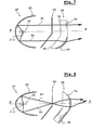
- Figure 7 schematically illustrates the operation of the additional spotlight 18 when it makes a highway beam Fa.
- the reflector 20 having a parabolic profile, the light rays R1, R2, which are emitted by the source 22 towards the reflector 20, are reflected towards the element lens 26 in a direction substantially parallel to the axis longitudinal B-B.
- R1 spokes which reach the rear face 32 of the part front 28 are not deflected by the lens element 26.
- the rays R2 which reach the rear face 46 of the part lateral 30 are deflected towards the longitudinal axis B-B.
- the front portion 74 of the element lens 26 is shaped as a half-lens of the spherical type, and the lateral part 76 is shaped as a semi-cylindrical lens.
- the imaging of the light beam Fa in the axis A-A of the vehicle 10 is optimized and the imagery of the turning beam Fv on the side is distributed laterally.
- the reflector 20 having a elliptical profile
- the light rays R3, R4 which are emitted by the source 22 towards the reflector 20, are reflected by converging towards the second focal point of the ellipse formed by the reflector 20.
- the rays R3, R4 therefore reach the rear entry faces of the lens element 26 with determined angles of inclination, so that these radii R3, R4 are deflected by the front part 74 and the lateral part 76 of the lens element 26 towards the axis longitudinal B-B.
Landscapes
- Engineering & Computer Science (AREA)
- General Engineering & Computer Science (AREA)
- Mechanical Engineering (AREA)
- Non-Portable Lighting Devices Or Systems Thereof (AREA)
- Lighting Device Outwards From Vehicle And Optical Signal (AREA)
Abstract
Description
- la partie latérale de l'élément de lentille comporte au moins une portion intermédiaire qui est adjacente à la portion latérale d'extrémité et dont le profil convexe, en section par un plan vertical, évolue angulairement le long de la partie latérale, de manière que la largeur du faisceau de virage augmente progressivement avec l'augmentation de l'angle de virage, depuis la position de repos ;
- la partie frontale de l'élément de lentille est une lentille semi-cylindrique d'axe sensiblement horizontal et la portion latérale d'extrémité de la partie latérale est une portion de lentille du type sphérique ;
- le réflecteur comporte une génératrice horizontale sensiblement parabolique et une génératrice verticale sensiblement elliptique ;
- la partie frontale de l'élément de lentille est une portion de lentille du type sphérique et la portion latérale d'extrémité de la partie latérale est une lentille semi-cylindrique d'axe sensiblement horizontal ;
- le projecteur comporte un cache fixe qui est agencé
longitudinalement entre le réflecteur et l'élément de lentille, et qui
comprend :
- une partie frontale qui est sensiblement orthogonale à l'axe longitudinal et qui est agencée globalement dans le plan focal de la partie frontale de l'élément de lentille ; et
- une partie latérale qui est conformée de manière qu'elle soit sensiblement orthogonale à au moins un axe optique de la partie latérale de l'élément de lentille.
- le cache comporte une partie supérieure qui est agencée globalement dans le plan focal de la partie frontale de l'élément de lentille, et qui délimite avec la partie frontale du cache une fenêtre de passage des rayons lumineux, de manière à diminuer la lumière proche émise par le projecteur sur la route, lorsque le réflecteur occupe sa position angulaire de repos ;
- la partie frontale et la partie latérale du cache sont formées chacune par deux plaques globalement rectangulaires et parallèles, alignées longitudinalement.
- la figure 1 est une vue de dessus qui représente schématiquement un véhicule équipé d'un système d'éclairage conforme aux enseignements de l'invention ;
- la figure 2 est une vue en perspective qui représente schématiquement le projecteur additionnel du bloc optique droit du véhicule de la figure 1 ;
- la figure 3 est une vue de dessus qui représente schématiquement le projecteur additionnel de la figure 2 ;
- la figure 4 est un schéma qui représente, sous la forme de courbes isolux, le faisceau d'autoroute réalisé par le projecteur additionnel de la figure 2, lorsque le réflecteur occupe sa position angulaire de repos ;
- la figure 5 est un schéma similaire à celui de la figure 4 qui représente le faisceau de virage réalisé par le projecteur additionnel de la figure 2, lorsque le réflecteur forme un angle de virage de vingt degrés par rapport à un axe longitudinal de référence ;
- la figure 6 est un schéma similaire à celui de la figure 4 qui représente le faisceau de virage réalisé par le projecteur additionnel de la figure 2, lorsque le réflecteur forme un angle de virage de quarante degrés par rapport à l'axe longitudinal de référence ;
- la figure 7 est une vue en coupe axiale partielle suivant le plan de coupe 7-7 qui représente schématiquement le fonctionnement du projecteur additionnel de la figure 2, lorsque le réflecteur occupe sa position angulaire de repos ;
- la figure 8 est une vue similaire à celle de la figure 7 qui représente schématiquement le fonctionnement d'une variante de réalisation du projecteur additionnel conforme aux enseignements de l'invention, lorsque le réflecteur occupe sa position angulaire de repos.
- une partie dite frontale 28, qui est adjacente au côté gauche de l'axe longitudinal B-B ;
- une partie dite latérale 30, qui est adjacente au côté droit de l'axe longitudinal B-B, et qui est agencée dans un secteur angulaire susceptible d'être balayé par l'axe optique mobile D-D.
- une portion latérale d'extrémité 36, dont l'axe optique E-E forme avec l'axe longitudinal B-B un angle déterminé qui est sensiblement égal à l'angle de virage maximal avmax ;
- une première portion intermédiaire 38 qui est adjacente au côté gauche de la portion latérale d'extrémité 36 ;
- une deuxième portion intermédiaire 40 qui est adjacente d'un côté à la première portion intermédiaire 38, et de l'autre côté à la partie frontale 28.
- une partie frontale 62 qui est sensiblement orthogonale à l'axe longitudinal B-B et qui est agencée globalement dans le plan focal de la partie frontale 28 de l'élément de lentille 26 ; et
- une partie latérale 64 qui est conformée de manière qu'elle soit sensiblement orthogonale à au moins un axe optique de la partie latérale 30 de l'élément de lentille 26.
Claims (10)
- Projecteur d'éclairage (18) de véhicule automobile (10) qui est conçu pour réaliser au moins un faisceau d'éclairage dit de virage (Fv) en vue d'améliorer l'éclairage lorsque le véhicule (10) aborde un virage, du type comportant un système optique qui comprend, agencés d'arrière en avant globalement suivant un axe longitudinal horizontal de référence (B-B), un réflecteur (20) du type elliptique, une source lumineuse (22) agencée au voisinage d'un premier foyer du réflecteur (20), et un élément de lentille convergente (26), du type dans lequel au moins le réflecteur (20) et la source lumineuse (22) sont montés pivotants autour d'un axe (C-C) sensiblement vertical, par rapport à un support fixe du véhicule (10), en fonction de l'angle de braquage des roues directrices du véhicule (10), définissant ainsi un axe optique mobile (D-D) par rapport à l'axe longitudinal (B-B),
caractérisé en ce que l'élément de lentille (26) est fixe par rapport au support, et en ce que l'élément de lentille (26) comporte une partie dite latérale (30), qui est agencée à côté de l'axe longitudinal (B-B), dans un secteur angulaire susceptible d'être balayé par l'axe optique mobile (D-D), et qui est conçue pour provoquer une modification du faisceau de virage (Fv) en fonction de l'angle de virage (av) que forme l'axe optique mobile avec l'axe longitudinal (B-B). - Projecteur (18) selon la revendication précédente, caractérisé en ce que l'élément de lentille (26) comporte une partie frontale (28) adjacente à la partie latérale (30), dont l'axe optique est sensiblement parallèle à l'axe longitudinal (B-B) et dont le plan focal est situé au voisinage du second foyer du réflecteur (20), lorsque le réflecteur (20) occupe sa position angulaire de repos, dans laquelle l'axe optique mobile (D-D) est sensiblement confondu avec l'axe longitudinal (B-B), de manière que le projecteur (18) puisse réaliser au moins un faisceau d'éclairage additionnel réglementaire, par exemple un faisceau d'éclairage (Fa) pour la circulation sur autoroute, lorsque le réflecteur (20) occupe sa position de repos.
- Projecteur (18) selon l'une quelconque des revendications précédentes, caractérisé en ce que la partie latérale (30) de l'élément de lentille (26) comporte une portion latérale d'extrémité (36) dont l'axe optique (E-E) forme avec l'axe longitudinal (B-B) un angle déterminé qui est sensiblement égal à l'angle de virage maximal (avmax).
- Projecteur (18) selon la revendication précédente, caractérisé en ce que la partie latérale (36) de l'élément de lentille (26) comporte au moins une portion intermédiaire (38, 40) qui est adjacente à la portion latérale d'extrémité (36) et dont le profil convexe, en section par un plan vertical, évolue angulairement le long de la partie latérale (30), de manière que la largeur du faisceau de virage (Fv) augmente progressivement avec l'augmentation de l'angle de virage (av), depuis la position de repos.
- Projecteur (10) selon l'une quelconque des revendications 3 ou 4 prise en combinaison avec la revendication 2, caractérisé en ce que la partie frontale (28) de l'élément de lentille (26) est une lentille semi-cylindrique d'axe sensiblement horizontal et la portion latérale d'extrémité (36) de la partie latérale (30) est une portion de lentille du type sphérique.
- Projecteur (10) selon la revendication précédente, caractérisé en ce que le réflecteur (20) comporte une génératrice horizontale sensiblement parabolique et une génératrice verticale sensiblement elliptique.
- Projecteur (10) selon l'une quelconque des revendications 3 ou 4 prise en combinaison avec la revendication 2, caractérisé en ce que la partie frontale (28) de l'élément de lentille (26) est une portion de lentille du type sphérique et la portion latérale d'extrémité (36) de la partie latérale (30) est une lentille semi-cylindrique d'axe sensiblement horizontal.
- Projecteur (10) selon l'une quelconque des revendications 2 à 7, caractérisé en ce qu'il comporte un cache fixe (24) qui est agencé longitudinalement entre le réflecteur (20) et l'élément de lentille (26), et qui comprend :une partie frontale (62) qui est sensiblement orthogonale à l'axe longitudinal (B-B) et qui est agencée globalement dans le plan focal de la partie frontale (28) de l'élément de lentille (26) ; etune partie latérale (64) qui est conformée de manière qu'elle soit sensiblement orthogonale à au moins un axe optique (E-E) de la partie latérale (30) de l'élément de lentille (26).
- Projecteur (10) selon la revendication précédente, caractérisé en ce que le cache (24) comporte une partie supérieure (70) qui est agencée globalement dans le plan focal de la partie frontale (28, 74) de l'élément de lentille (26), et qui délimite avec la partie frontale (62) du cache (24) une fenêtre de passage des rayons lumineux, de manière à diminuer la lumière proche émise par le projecteur (18) sur la route, lorsque le réflecteur (20) occupe sa position angulaire de repos.
- Projecteur selon l'une quelconque des revendications 8 ou 9, caractérisé en ce que la partie frontale (62) et la partie latérale (64) du cache (24) sont formées chacune par deux plaques (58, 60) globalement rectangulaires et parallèles, alignées longitudinalement.
Applications Claiming Priority (2)
| Application Number | Priority Date | Filing Date | Title |
|---|---|---|---|
| FR0203935 | 2002-03-28 | ||
| FR0203935A FR2837908B1 (fr) | 2002-03-28 | 2002-03-28 | Projecteur d'eclairage equipe d'un reflecteur elliptique pivotant et d'une lentille fixe pour la realisation d'un faisceau de virage |
Publications (2)
| Publication Number | Publication Date |
|---|---|
| EP1348594A1 true EP1348594A1 (fr) | 2003-10-01 |
| EP1348594B1 EP1348594B1 (fr) | 2005-09-14 |
Family
ID=27799287
Family Applications (1)
| Application Number | Title | Priority Date | Filing Date |
|---|---|---|---|
| EP03290681A Expired - Lifetime EP1348594B1 (fr) | 2002-03-28 | 2003-03-18 | Projecteur d'éclairage équipé d'un réflecteur elliptique pivotant et d'une lentille fixe pour la réalisation d'un faisceau de virage |
Country Status (7)
| Country | Link |
|---|---|
| US (1) | US6910790B2 (fr) |
| EP (1) | EP1348594B1 (fr) |
| JP (1) | JP2003306076A (fr) |
| AT (1) | ATE304461T1 (fr) |
| DE (1) | DE60301586T2 (fr) |
| ES (1) | ES2248711T3 (fr) |
| FR (1) | FR2837908B1 (fr) |
Cited By (1)
| Publication number | Priority date | Publication date | Assignee | Title |
|---|---|---|---|---|
| FR3099228A1 (fr) * | 2019-07-26 | 2021-01-29 | Psa Automobiles Sa | Dispositif d’éclairage pour véhicule |
Families Citing this family (7)
| Publication number | Priority date | Publication date | Assignee | Title |
|---|---|---|---|---|
| US7810972B2 (en) * | 2006-10-13 | 2010-10-12 | Visteon Global Technologies, Inc. | Headlamp assembly having an adjustable light beam direction |
| JP4987636B2 (ja) * | 2007-09-05 | 2012-07-25 | 株式会社小糸製作所 | 車輌用前照灯 |
| JP4697215B2 (ja) * | 2007-11-20 | 2011-06-08 | 市光工業株式会社 | 車両用灯具 |
| JP5626059B2 (ja) * | 2011-03-23 | 2014-11-19 | 市光工業株式会社 | 車両用灯具 |
| KR102674556B1 (ko) * | 2016-12-16 | 2024-06-13 | 현대자동차주식회사 | 차량용 픽셀라이트 헤드램프 |
| EP4197859B1 (fr) * | 2021-12-17 | 2024-08-28 | ZKW Group GmbH | Optique primaire avec guides de lumiere pour phare de motocyclette |
| KR20240104941A (ko) * | 2022-12-28 | 2024-07-05 | 현대모비스 주식회사 | 차량용 램프 |
Citations (5)
| Publication number | Priority date | Publication date | Assignee | Title |
|---|---|---|---|---|
| FR1536280A (fr) * | 1967-06-13 | 1968-08-16 | Cibie Projecteurs | Perfectionnements aux projecteurs tournants pour véhicules automobiles |
| US5412543A (en) * | 1992-02-28 | 1995-05-02 | Koito Manufacturing Co., Ltd. | Variable light distribution type headlamp |
| FR2772882A1 (fr) * | 1997-12-18 | 1999-06-25 | Bosch Gmbh Robert | Projecteur de vehicule automobile pour les feux de croisement et les feux de route |
| FR2776366A1 (fr) * | 1998-03-19 | 1999-09-24 | Valeo Vision | Projecteur de virage pour vehicule automobile, susceptible d'emettre des faisceaux differents |
| US6309094B1 (en) * | 1999-09-28 | 2001-10-30 | Robert Bosch Gmbh | Projection headlight with rotatable reflector and light source and illumination device for a vehicle containing same |
Family Cites Families (12)
| Publication number | Priority date | Publication date | Assignee | Title |
|---|---|---|---|---|
| FR94279E (fr) | 1967-06-13 | 1969-07-25 | Cibie Projecteurs | Perfectionnements aux projecteurs tournants pour véhicules automobiles. |
| FR2536503B1 (fr) | 1982-11-19 | 1987-12-31 | Cibie Projecteurs | Projecteur antibrouillard pour vehicule automobile |
| FR2602305B1 (fr) | 1986-08-04 | 1990-03-23 | Cibie Projecteurs | Projecteur antibrouillard a filament transversal pour vehicule automobile |
| JP2622564B2 (ja) | 1986-12-30 | 1997-06-18 | ヴァレオ ヴイジョン | カットオフによって限定されたビームを放射する、変形底部を有する自動車用前照灯 |
| FR2609148B1 (fr) | 1986-12-30 | 1991-07-12 | Cibie Projecteurs | Projecteur de vehicule automobile comportant un reflecteur a surface complexe a fond modifie |
| KR940003752B1 (ko) * | 1987-01-23 | 1994-04-30 | 박성예 | 자동차의 광전 제어식 측방 조명장치. |
| FR2639888B1 (fr) | 1988-12-07 | 1993-08-13 | Valeo Vision | Projecteur de vehicule automobile, comportant un reflecteur a surface complexe a zones intermediaires modifiees |
| FR2664677A1 (fr) | 1990-07-13 | 1992-01-17 | Valeo Vision | Reflecteur pour un dispositif d'eclairage de vehicule automobile, et projecteur et feu de signalisation incorporant un tel reflecteur. |
| EP0854316B1 (fr) * | 1997-01-17 | 2005-04-27 | Stanley Electric Co., Ltd. | Projecteur |
| WO1999011969A1 (fr) | 1997-09-03 | 1999-03-11 | Valeo Vision | Projecteur pour vehicule automobile, susceptible d'emettre des faisceaux differents |
| US6447152B1 (en) * | 2000-05-24 | 2002-09-10 | Deere & Company | Wide-angle headlighting and sidelighting assembly |
| JP3634763B2 (ja) * | 2001-03-23 | 2005-03-30 | スタンレー電気株式会社 | プロジェクタ型ランプ |
-
2002
- 2002-03-28 FR FR0203935A patent/FR2837908B1/fr not_active Expired - Fee Related
-
2003
- 2003-03-18 AT AT03290681T patent/ATE304461T1/de not_active IP Right Cessation
- 2003-03-18 EP EP03290681A patent/EP1348594B1/fr not_active Expired - Lifetime
- 2003-03-18 DE DE60301586T patent/DE60301586T2/de not_active Expired - Lifetime
- 2003-03-18 ES ES03290681T patent/ES2248711T3/es not_active Expired - Lifetime
- 2003-03-21 US US10/393,645 patent/US6910790B2/en not_active Expired - Lifetime
- 2003-03-28 JP JP2003090354A patent/JP2003306076A/ja active Pending
Patent Citations (5)
| Publication number | Priority date | Publication date | Assignee | Title |
|---|---|---|---|---|
| FR1536280A (fr) * | 1967-06-13 | 1968-08-16 | Cibie Projecteurs | Perfectionnements aux projecteurs tournants pour véhicules automobiles |
| US5412543A (en) * | 1992-02-28 | 1995-05-02 | Koito Manufacturing Co., Ltd. | Variable light distribution type headlamp |
| FR2772882A1 (fr) * | 1997-12-18 | 1999-06-25 | Bosch Gmbh Robert | Projecteur de vehicule automobile pour les feux de croisement et les feux de route |
| FR2776366A1 (fr) * | 1998-03-19 | 1999-09-24 | Valeo Vision | Projecteur de virage pour vehicule automobile, susceptible d'emettre des faisceaux differents |
| US6309094B1 (en) * | 1999-09-28 | 2001-10-30 | Robert Bosch Gmbh | Projection headlight with rotatable reflector and light source and illumination device for a vehicle containing same |
Cited By (1)
| Publication number | Priority date | Publication date | Assignee | Title |
|---|---|---|---|---|
| FR3099228A1 (fr) * | 2019-07-26 | 2021-01-29 | Psa Automobiles Sa | Dispositif d’éclairage pour véhicule |
Also Published As
| Publication number | Publication date |
|---|---|
| FR2837908A1 (fr) | 2003-10-03 |
| US20030189822A1 (en) | 2003-10-09 |
| ATE304461T1 (de) | 2005-09-15 |
| US6910790B2 (en) | 2005-06-28 |
| FR2837908B1 (fr) | 2004-06-11 |
| EP1348594B1 (fr) | 2005-09-14 |
| JP2003306076A (ja) | 2003-10-28 |
| ES2248711T3 (es) | 2006-03-16 |
| DE60301586T2 (de) | 2006-06-22 |
| DE60301586D1 (de) | 2005-10-20 |
Similar Documents
| Publication | Publication Date | Title |
|---|---|---|
| EP3301348B1 (fr) | Dispositif d'éclairage en bandes pour projecteur de véhicule automobile | |
| EP2199664B1 (fr) | Dispositif d'éclairage pour projecteur de véhicule assurant plusieurs fonctions d'éclairage ou une fonction variable avec une seule source lumineuse | |
| EP1308669A1 (fr) | Dispositif d'éclairage de type elliptique pour véhicule automobile | |
| FR2819578A1 (fr) | Phare de vehicule a eclairage reglable lateralement | |
| FR2999679A1 (fr) | Element optique primaire, module d'eclairage et projecteur pour vehicule automobile. | |
| EP1746340B1 (fr) | Module optique pour dispositif d'éclairage automobile | |
| FR2995967B1 (fr) | Module d'eclairage, notamment pour vehicule automobile | |
| FR3012867A1 (fr) | Element optique primaire, module lumineux et projecteur pour vehicule automobile | |
| EP3027961B1 (fr) | Système d'éclairage pour véhicule automobile | |
| EP4264120A1 (fr) | Projecteur automobile avec plusieurs modules d'éclairage sur une platine commune inclinée | |
| EP4377151B1 (fr) | Module lumineux pour véhicule automobile | |
| EP2597360A1 (fr) | Dispositif d'émission de lumière pour projecteur de véhicule automobile | |
| EP1348594B1 (fr) | Projecteur d'éclairage équipé d'un réflecteur elliptique pivotant et d'une lentille fixe pour la réalisation d'un faisceau de virage | |
| EP3470727A1 (fr) | Module d'éclairage formant un motif lumineux divisé en une portion supérieure aux bords verticaux nets et une portion inférieure aux bords verticaux floux | |
| EP2436968A1 (fr) | Dispositif d'émission de lumière pour projecteur de véhicule automobile | |
| EP1944542B1 (fr) | Projecteur lumineux de type bifonction pour véhicule automobile | |
| FR2966221A1 (fr) | Module d'eclairage a coupure avec reflecteur parabolique dispose sur un reflecteur elliptique | |
| EP1170546A1 (fr) | Projecteur elliptique à modification de faisceau par mouvement d'éléments optiques | |
| FR2808867A1 (fr) | Projecteur bi-fonction a source lumineuse unique et occulteur mobile pour vehicule automobile | |
| FR2777976A1 (fr) | Projecteur a faisceau variable, notamment pour vehicules, et ensemble de projecteurs de ce type | |
| EP2366941A2 (fr) | Module d'éclairage avec deux réflecteurs de distances focales différentes | |
| FR2774151A1 (fr) | Projecteur de vehicule automobile a source lumineuse virtuelle | |
| FR2776366A1 (fr) | Projecteur de virage pour vehicule automobile, susceptible d'emettre des faisceaux differents | |
| EP1111294A1 (fr) | Projecteur de véhicule automobile à spécialisation sélective | |
| FR2797030A1 (fr) | Projecteur du genre elliptique pour vehicule automobile, susceptible d'engendrer un faisceau lumineux a deux fonctions |
Legal Events
| Date | Code | Title | Description |
|---|---|---|---|
| PUAI | Public reference made under article 153(3) epc to a published international application that has entered the european phase |
Free format text: ORIGINAL CODE: 0009012 |
|
| AK | Designated contracting states |
Kind code of ref document: A1 Designated state(s): AT BE BG CH CY CZ DE DK EE ES FI FR GB GR HU IE IT LI LU MC NL PT RO SE SI SK TR |
|
| AX | Request for extension of the european patent |
Extension state: AL LT LV MK |
|
| AKX | Designation fees paid | ||
| 17P | Request for examination filed |
Effective date: 20031106 |
|
| RBV | Designated contracting states (corrected) |
Designated state(s): AT BE BG CH CY CZ DE DK EE ES FI FR GB GR HU IE IT LI LU MC NL PT RO SE SI SK TR |
|
| REG | Reference to a national code |
Ref country code: DE Ref legal event code: 8566 |
|
| GRAP | Despatch of communication of intention to grant a patent |
Free format text: ORIGINAL CODE: EPIDOSNIGR1 |
|
| GRAS | Grant fee paid |
Free format text: ORIGINAL CODE: EPIDOSNIGR3 |
|
| GRAA | (expected) grant |
Free format text: ORIGINAL CODE: 0009210 |
|
| AK | Designated contracting states |
Kind code of ref document: B1 Designated state(s): AT BE BG CH CY CZ DE DK EE ES FI FR GB GR HU IE IT LI LU MC NL PT RO SE SI SK TR |
|
| PG25 | Lapsed in a contracting state [announced via postgrant information from national office to epo] |
Ref country code: SK Free format text: LAPSE BECAUSE OF FAILURE TO SUBMIT A TRANSLATION OF THE DESCRIPTION OR TO PAY THE FEE WITHIN THE PRESCRIBED TIME-LIMIT Effective date: 20050914 Ref country code: IE Free format text: LAPSE BECAUSE OF FAILURE TO SUBMIT A TRANSLATION OF THE DESCRIPTION OR TO PAY THE FEE WITHIN THE PRESCRIBED TIME-LIMIT Effective date: 20050914 Ref country code: FI Free format text: LAPSE BECAUSE OF FAILURE TO SUBMIT A TRANSLATION OF THE DESCRIPTION OR TO PAY THE FEE WITHIN THE PRESCRIBED TIME-LIMIT Effective date: 20050914 Ref country code: NL Free format text: LAPSE BECAUSE OF FAILURE TO SUBMIT A TRANSLATION OF THE DESCRIPTION OR TO PAY THE FEE WITHIN THE PRESCRIBED TIME-LIMIT Effective date: 20050914 Ref country code: SI Free format text: LAPSE BECAUSE OF FAILURE TO SUBMIT A TRANSLATION OF THE DESCRIPTION OR TO PAY THE FEE WITHIN THE PRESCRIBED TIME-LIMIT Effective date: 20050914 Ref country code: AT Free format text: LAPSE BECAUSE OF FAILURE TO SUBMIT A TRANSLATION OF THE DESCRIPTION OR TO PAY THE FEE WITHIN THE PRESCRIBED TIME-LIMIT Effective date: 20050914 Ref country code: RO Free format text: LAPSE BECAUSE OF FAILURE TO SUBMIT A TRANSLATION OF THE DESCRIPTION OR TO PAY THE FEE WITHIN THE PRESCRIBED TIME-LIMIT Effective date: 20050914 Ref country code: CZ Free format text: LAPSE BECAUSE OF FAILURE TO SUBMIT A TRANSLATION OF THE DESCRIPTION OR TO PAY THE FEE WITHIN THE PRESCRIBED TIME-LIMIT Effective date: 20050914 |
|
| REG | Reference to a national code |
Ref country code: GB Ref legal event code: FG4D Free format text: NOT ENGLISH |
|
| REG | Reference to a national code |
Ref country code: CH Ref legal event code: EP |
|
| REG | Reference to a national code |
Ref country code: IE Ref legal event code: FG4D Free format text: LANGUAGE OF EP DOCUMENT: FRENCH |
|
| REF | Corresponds to: |
Ref document number: 60301586 Country of ref document: DE Date of ref document: 20051020 Kind code of ref document: P |
|
| PG25 | Lapsed in a contracting state [announced via postgrant information from national office to epo] |
Ref country code: SE Free format text: LAPSE BECAUSE OF FAILURE TO SUBMIT A TRANSLATION OF THE DESCRIPTION OR TO PAY THE FEE WITHIN THE PRESCRIBED TIME-LIMIT Effective date: 20051214 Ref country code: BG Free format text: LAPSE BECAUSE OF FAILURE TO SUBMIT A TRANSLATION OF THE DESCRIPTION OR TO PAY THE FEE WITHIN THE PRESCRIBED TIME-LIMIT Effective date: 20051214 Ref country code: GR Free format text: LAPSE BECAUSE OF FAILURE TO SUBMIT A TRANSLATION OF THE DESCRIPTION OR TO PAY THE FEE WITHIN THE PRESCRIBED TIME-LIMIT Effective date: 20051214 Ref country code: DK Free format text: LAPSE BECAUSE OF FAILURE TO SUBMIT A TRANSLATION OF THE DESCRIPTION OR TO PAY THE FEE WITHIN THE PRESCRIBED TIME-LIMIT Effective date: 20051214 |
|
| GBT | Gb: translation of ep patent filed (gb section 77(6)(a)/1977) |
Effective date: 20051220 |
|
| PG25 | Lapsed in a contracting state [announced via postgrant information from national office to epo] |
Ref country code: PT Free format text: LAPSE BECAUSE OF FAILURE TO SUBMIT A TRANSLATION OF THE DESCRIPTION OR TO PAY THE FEE WITHIN THE PRESCRIBED TIME-LIMIT Effective date: 20060214 |
|
| NLV1 | Nl: lapsed or annulled due to failure to fulfill the requirements of art. 29p and 29m of the patents act | ||
| PG25 | Lapsed in a contracting state [announced via postgrant information from national office to epo] |
Ref country code: HU Free format text: LAPSE BECAUSE OF FAILURE TO SUBMIT A TRANSLATION OF THE DESCRIPTION OR TO PAY THE FEE WITHIN THE PRESCRIBED TIME-LIMIT Effective date: 20060315 |
|
| REG | Reference to a national code |
Ref country code: ES Ref legal event code: FG2A Ref document number: 2248711 Country of ref document: ES Kind code of ref document: T3 |
|
| PG25 | Lapsed in a contracting state [announced via postgrant information from national office to epo] |
Ref country code: BE Free format text: LAPSE BECAUSE OF NON-PAYMENT OF DUE FEES Effective date: 20060331 Ref country code: LU Free format text: LAPSE BECAUSE OF NON-PAYMENT OF DUE FEES Effective date: 20060331 Ref country code: MC Free format text: LAPSE BECAUSE OF NON-PAYMENT OF DUE FEES Effective date: 20060331 |
|
| REG | Reference to a national code |
Ref country code: IE Ref legal event code: FD4D |
|
| PLBE | No opposition filed within time limit |
Free format text: ORIGINAL CODE: 0009261 |
|
| STAA | Information on the status of an ep patent application or granted ep patent |
Free format text: STATUS: NO OPPOSITION FILED WITHIN TIME LIMIT |
|
| 26N | No opposition filed |
Effective date: 20060615 |
|
| REG | Reference to a national code |
Ref country code: FR Ref legal event code: ST Effective date: 20061130 |
|
| PGFP | Annual fee paid to national office [announced via postgrant information from national office to epo] |
Ref country code: GB Payment date: 20070313 Year of fee payment: 5 |
|
| REG | Reference to a national code |
Ref country code: CH Ref legal event code: PL |
|
| BERE | Be: lapsed |
Owner name: VALEO VISION Effective date: 20060331 |
|
| PG25 | Lapsed in a contracting state [announced via postgrant information from national office to epo] |
Ref country code: FR Free format text: LAPSE BECAUSE OF NON-PAYMENT OF DUE FEES Effective date: 20060331 |
|
| PG25 | Lapsed in a contracting state [announced via postgrant information from national office to epo] |
Ref country code: LI Free format text: LAPSE BECAUSE OF NON-PAYMENT OF DUE FEES Effective date: 20070331 Ref country code: CH Free format text: LAPSE BECAUSE OF NON-PAYMENT OF DUE FEES Effective date: 20070331 |
|
| PG25 | Lapsed in a contracting state [announced via postgrant information from national office to epo] |
Ref country code: EE Free format text: LAPSE BECAUSE OF FAILURE TO SUBMIT A TRANSLATION OF THE DESCRIPTION OR TO PAY THE FEE WITHIN THE PRESCRIBED TIME-LIMIT Effective date: 20050914 |
|
| PG25 | Lapsed in a contracting state [announced via postgrant information from national office to epo] |
Ref country code: TR Free format text: LAPSE BECAUSE OF FAILURE TO SUBMIT A TRANSLATION OF THE DESCRIPTION OR TO PAY THE FEE WITHIN THE PRESCRIBED TIME-LIMIT Effective date: 20050914 |
|
| GBPC | Gb: european patent ceased through non-payment of renewal fee |
Effective date: 20080318 |
|
| PG25 | Lapsed in a contracting state [announced via postgrant information from national office to epo] |
Ref country code: CY Free format text: LAPSE BECAUSE OF FAILURE TO SUBMIT A TRANSLATION OF THE DESCRIPTION OR TO PAY THE FEE WITHIN THE PRESCRIBED TIME-LIMIT Effective date: 20050914 |
|
| PG25 | Lapsed in a contracting state [announced via postgrant information from national office to epo] |
Ref country code: GB Free format text: LAPSE BECAUSE OF NON-PAYMENT OF DUE FEES Effective date: 20080318 |
|
| PGFP | Annual fee paid to national office [announced via postgrant information from national office to epo] |
Ref country code: IT Payment date: 20200312 Year of fee payment: 18 Ref country code: DE Payment date: 20200311 Year of fee payment: 18 |
|
| PGFP | Annual fee paid to national office [announced via postgrant information from national office to epo] |
Ref country code: ES Payment date: 20200423 Year of fee payment: 18 |
|
| REG | Reference to a national code |
Ref country code: DE Ref legal event code: R119 Ref document number: 60301586 Country of ref document: DE |
|
| PG25 | Lapsed in a contracting state [announced via postgrant information from national office to epo] |
Ref country code: DE Free format text: LAPSE BECAUSE OF NON-PAYMENT OF DUE FEES Effective date: 20211001 |
|
| PG25 | Lapsed in a contracting state [announced via postgrant information from national office to epo] |
Ref country code: IT Free format text: LAPSE BECAUSE OF NON-PAYMENT OF DUE FEES Effective date: 20210318 |
|
| REG | Reference to a national code |
Ref country code: ES Ref legal event code: FD2A Effective date: 20220523 |
|
| PG25 | Lapsed in a contracting state [announced via postgrant information from national office to epo] |
Ref country code: ES Free format text: LAPSE BECAUSE OF NON-PAYMENT OF DUE FEES Effective date: 20210319 |