EP1347856B1 - Bandsaw blade for metal and a method for manufacturing a bandsaw blade with teeth - Google Patents
Bandsaw blade for metal and a method for manufacturing a bandsaw blade with teeth Download PDFInfo
- Publication number
- EP1347856B1 EP1347856B1 EP01997372A EP01997372A EP1347856B1 EP 1347856 B1 EP1347856 B1 EP 1347856B1 EP 01997372 A EP01997372 A EP 01997372A EP 01997372 A EP01997372 A EP 01997372A EP 1347856 B1 EP1347856 B1 EP 1347856B1
- Authority
- EP
- European Patent Office
- Prior art keywords
- teeth
- tooth
- bandsaw blade
- land
- lands
- Prior art date
- Legal status (The legal status is an assumption and is not a legal conclusion. Google has not performed a legal analysis and makes no representation as to the accuracy of the status listed.)
- Expired - Lifetime
Links
Images
Classifications
-
- B—PERFORMING OPERATIONS; TRANSPORTING
- B23—MACHINE TOOLS; METAL-WORKING NOT OTHERWISE PROVIDED FOR
- B23D—PLANING; SLOTTING; SHEARING; BROACHING; SAWING; FILING; SCRAPING; LIKE OPERATIONS FOR WORKING METAL BY REMOVING MATERIAL, NOT OTHERWISE PROVIDED FOR
- B23D65/00—Making tools for sawing machines or sawing devices for use in cutting any kind of material
-
- Y—GENERAL TAGGING OF NEW TECHNOLOGICAL DEVELOPMENTS; GENERAL TAGGING OF CROSS-SECTIONAL TECHNOLOGIES SPANNING OVER SEVERAL SECTIONS OF THE IPC; TECHNICAL SUBJECTS COVERED BY FORMER USPC CROSS-REFERENCE ART COLLECTIONS [XRACs] AND DIGESTS
- Y10—TECHNICAL SUBJECTS COVERED BY FORMER USPC
- Y10T—TECHNICAL SUBJECTS COVERED BY FORMER US CLASSIFICATION
- Y10T83/00—Cutting
- Y10T83/707—By endless band or chain knife
-
- Y—GENERAL TAGGING OF NEW TECHNOLOGICAL DEVELOPMENTS; GENERAL TAGGING OF CROSS-SECTIONAL TECHNOLOGIES SPANNING OVER SEVERAL SECTIONS OF THE IPC; TECHNICAL SUBJECTS COVERED BY FORMER USPC CROSS-REFERENCE ART COLLECTIONS [XRACs] AND DIGESTS
- Y10—TECHNICAL SUBJECTS COVERED BY FORMER USPC
- Y10T—TECHNICAL SUBJECTS COVERED BY FORMER US CLASSIFICATION
- Y10T83/00—Cutting
- Y10T83/929—Tool or tool with support
- Y10T83/9317—Endless band or belt type
-
- Y—GENERAL TAGGING OF NEW TECHNOLOGICAL DEVELOPMENTS; GENERAL TAGGING OF CROSS-SECTIONAL TECHNOLOGIES SPANNING OVER SEVERAL SECTIONS OF THE IPC; TECHNICAL SUBJECTS COVERED BY FORMER USPC CROSS-REFERENCE ART COLLECTIONS [XRACs] AND DIGESTS
- Y10—TECHNICAL SUBJECTS COVERED BY FORMER USPC
- Y10T—TECHNICAL SUBJECTS COVERED BY FORMER US CLASSIFICATION
- Y10T83/00—Cutting
- Y10T83/929—Tool or tool with support
- Y10T83/9319—Toothed blade or tooth therefor
Definitions
- the cutting depth per tooth is about 10 micrometers, which is of the same order as the depth variations between teeth produced by milling or grinding the teeth in traditional ways.
- the teeth are wom to a fairly even height without risk of overloading.
- some of the cutting edges will be rounded-off so that the cutting forces increase.
- a problem especially encountered at bandsaws is vibrations in the plane of the sawblade, caused by sharp edges with large clearance angle being able to penetrate into the metal with so low feed force and so little difference between increasing and decreasing cutting depth, that all teeth engaged in cutting will produce vibrations with the same frequency, and since the cut bottom surface will become corrugated, they will amplify each other's vibrations.
- Recently mounted sawblades will cause a very annoying high frequency noise, which will be reduced when the teeth get somewhat worn, since there will then be more of a difference in feed force between increasing and decreasing cutting depth.
- the present invention concerns a handsaw blade according to claim 1 and a method for manufacture of bandsaw blades according to claim 3, where all cutting edges are sharp before use, and where all edges in a group with equal lateral slope also have equal cutting depth.
- Such a sawblade can immediately be used for cutting with full feed and cutting speed, it will wear more slowly than a sawblade according to prior art, and it will from the beginning produce less noise.
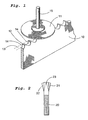
- Figure 1 shows a stage in manufacture of a handsaw blade, after forming the profile of the teeth by milling, grinding or brazing of carbide cutting edges, but prior to setting of the teeth as required, and prior to joining the band ends to form loops.
- Figure 2 shows a cross-section of the band after setting.
- a bandsaw blade 20 according to the invention may as shown in figure 2 be made with several groups of teeth, where the teeth in each group have equal lateral slope of the edge. Such groups can be set right 21, set left 22 or straight 23. The number of groups may also be more than three, by having two groups set right with different setting distance and angle, and correspondingly for those set left.
- the bandsaw blade may.also be made with all teeth straight.
- the teeth are supposed to have basically the same height before setting, with edges 24 at right angles to the plane of the blade. Due to wear or irregularities of the tools for forming the teeth, they will originally have some variation in height, which is small compared to the height, but comparable to the cutting depth per tooth. According to the method used in grinding or milling, the tooth edges are commonly uneven or rough, and the surfaces adjoining the edge may have crosswise scratches. Such edges are liable to get further damage by chipping or similar deformation. The previously mentioned method using low feed velocity and reduced power during the first few cuts will remove the scratches and lengthen the lifetime of the edges. It has also been suggested to remove the scratches by blasting or other abrasive methods which at the same time will make the edges slightly rounded, resulting in a stable sawing but requiring increased cutting force.
- the scratches are removed before the final steps of manufacturing the saw blade by honing with a fine grain abrasive material against the tooth tips.
- the teeth get very sharp cutting edges 14, narrow scratch-free tahds 12 on the clearance side and equal height. This makes it possible to use full cutting force and full cutting depth from the beginning, and the lands ensure stable chip formation.
- the lands 12 cause a greater feed force if the cutting depth increases, and a smaller feed force if the cutting depth is reducing, compared to teeth according to prior art.
- the force variation will then have such a time cycle which completely prevents the teeth from amplifying the vibration of each other, and bandsaw blades made according to the invention have been shown to reduce the noise by as much as 20 decibel.
- the width of the lands should not exceed 10 percent of the pitch distance between teeth, since friction on wider lands will need a greater cutting force.
- a method of manufacturing a bandsaw blade according to the invention comprises pulling the toothed blade 10 across one or more abrasive hones 11, which to avoid uneven wear of said hones are preferably made to rotate slowly.
- the axis of rotation 15 is preferably parallel to the plane of the saw blade but laterally offset relative to said plane.
- each tooth gets a flat land 12 on the clearance side, all said lands being in the same plane 13, and originally occurring variations in tooth height leading to variations in width of the lands 12.
- the leading edge of each land 12 is a cutting edge 14, which by the honing is sharper than without honing.
- the teeth forming each group thus have edges and lands at equal height before setting, and will retain equal height after setting, since members of each group have equal setting angle and setting width.
- the material of the hone is chosen with reference to the material of the teeth, and may preferably be fine-grain diamond or boron carbide with an elastic binder.
- the slow rotation of the hones will occur automatically if the axis of rotation 15 is offset a distance not exceeding half the radius of the hone, if desired combined with a slight braking. It would also be possible to have a powered rotation of the hone fitted to the feed velocity of the saw blade.
- Another type of hone could be one or more cylinders with large diameters and rotation axes parallel to the edge plane 13 but deviating from the length direction of the blade by an angle small enough to ensure a long enough contact time between each tooth and the hone.
Landscapes
- Engineering & Computer Science (AREA)
- Mechanical Engineering (AREA)
- Sawing (AREA)
- Scissors And Nippers (AREA)
- Gear Processing (AREA)
- Finish Polishing, Edge Sharpening, And Grinding By Specific Grinding Devices (AREA)
- Heat Treatment Of Articles (AREA)
- Polishing Bodies And Polishing Tools (AREA)
- Knives (AREA)
- Accessories And Tools For Shearing Machines (AREA)
Abstract
Description
Claims (3)
- A bandsaw blade for sawing of metal and provided with teeth, each tooth having a chip side and a clearance side that are meeting at an edge characterized by each tooth having on the clearance side and in comparison with the length and thickness of the tooth a narrow flat land (12) without clearance angle, said land having at its leading edge a sharp cutting edge (14), the width of said lands not exceeding 10 percent of the pitch distance between the teeth.
- A bandsaw blade according to claim 1, characterized by said lands being free of scratches and having less surface unevenness than other surfaces of the teeth.
- A method for manufacturing a bandsaw blade according to claim 1, characterized by the saw blade (10) before possible setting and before joining to loops being longitudinally moved with the teeth in contact with one or more slowly rotating hones (11) thereby providing each tooth with a flat land (12) without clearance angle on the clearance side, the leading edge of said land being a sharp cutting edge (14).
Applications Claiming Priority (3)
| Application Number | Priority Date | Filing Date | Title |
|---|---|---|---|
| SE0004305 | 2000-11-23 | ||
| SE0004305A SE521223C2 (en) | 2000-11-23 | 2000-11-23 | Saw blades for metal |
| PCT/SE2001/002580 WO2002042029A1 (en) | 2000-11-23 | 2001-11-22 | Bandsaw blade for metal and a method for manufacturing a bandsaw blade with teeth |
Publications (2)
| Publication Number | Publication Date |
|---|---|
| EP1347856A1 EP1347856A1 (en) | 2003-10-01 |
| EP1347856B1 true EP1347856B1 (en) | 2005-08-17 |
Family
ID=20281945
Family Applications (1)
| Application Number | Title | Priority Date | Filing Date |
|---|---|---|---|
| EP01997372A Expired - Lifetime EP1347856B1 (en) | 2000-11-23 | 2001-11-22 | Bandsaw blade for metal and a method for manufacturing a bandsaw blade with teeth |
Country Status (8)
| Country | Link |
|---|---|
| US (1) | US7908954B2 (en) |
| EP (1) | EP1347856B1 (en) |
| JP (1) | JP4143407B2 (en) |
| AT (1) | ATE302087T1 (en) |
| AU (1) | AU2002224272A1 (en) |
| DE (1) | DE60112798T2 (en) |
| SE (1) | SE521223C2 (en) |
| WO (1) | WO2002042029A1 (en) |
Families Citing this family (9)
| Publication number | Priority date | Publication date | Assignee | Title |
|---|---|---|---|---|
| US20110131790A1 (en) * | 2009-12-07 | 2011-06-09 | Po-Hsun Chien | Electromotive hair cutter |
| JP5584046B2 (en) * | 2010-08-10 | 2014-09-03 | 株式会社アマダ | Band saw blade manufacturing method |
| EP2495081B1 (en) * | 2011-03-01 | 2014-05-07 | GFD Gesellschaft für Diamantprodukte mbH | Cutting tool with blade made from fine-crystalline diamond |
| RU2566035C1 (en) * | 2014-06-04 | 2015-10-20 | Федеральное государственное бюджетное образовательное учреждение высшего образования "Воронежский государственный лесотехнический университет имени Г.Ф. Морозова" | Band-saw for processing of soft wood |
| US9975192B2 (en) | 2016-08-30 | 2018-05-22 | Simonds International L.L.C. | Systems and methods for milling saw blade tooth profiles and saw blades with milled tooth profiles |
| AT519562B1 (en) * | 2017-05-09 | 2018-08-15 | Gebrueder Busatis Ges M B H | Saw blade for a saw for cutting stalky stalks |
| JP6578412B1 (en) * | 2018-06-08 | 2019-09-18 | 株式会社アマダホールディングス | Manufacturing method and manufacturing apparatus for annular band saw blade |
| WO2020157661A1 (en) * | 2019-01-29 | 2020-08-06 | Stryker European Operations Limited | Saw blade with blunt teeth |
| RU2743759C1 (en) * | 2020-07-06 | 2021-02-25 | Федеральное государственное бюджетное образовательное учреждение высшего образования "Воронежский государственный лесотехнический университет имени Г.Ф. Морозова" | Band-saw for treatment of soft-leaved wood |
Family Cites Families (23)
| Publication number | Priority date | Publication date | Assignee | Title |
|---|---|---|---|---|
| US1649864A (en) * | 1923-06-25 | 1927-11-22 | Willis S Sherman | Saw |
| US1906660A (en) * | 1930-12-31 | 1933-05-02 | Smooth Saw Equipment Company | Saw blade |
| US2126382A (en) * | 1936-01-27 | 1938-08-09 | Stockton Box Company | Band saw |
| US2318549A (en) * | 1941-04-14 | 1943-05-04 | Continental Machines | Metal cutting saw band |
| US2442153A (en) * | 1946-04-23 | 1948-05-25 | Norton Co | Band saw with diamond abrasive teeth |
| GB821510A (en) * | 1956-12-21 | 1959-10-07 | Simmonds Aerocessories Ltd | Improvements in cutting elements |
| US3110952A (en) * | 1961-05-18 | 1963-11-19 | Doall Co | Carbide tipped saw blade |
| US3276491A (en) * | 1963-08-02 | 1966-10-04 | Marlan Company | Saw blade |
| USRE26676E (en) * | 1969-04-25 | 1969-09-30 | Method of making band saw blade | |
| US3965781A (en) * | 1972-01-01 | 1976-06-29 | Stroud Graphic Equipment Limited | Bandsaw book trimmer |
| US4351210A (en) * | 1978-11-20 | 1982-09-28 | Zimmer Manufacturing Corp. | Shear cut tooth |
| CA1163172A (en) * | 1979-06-20 | 1984-03-06 | Jonas W. Ask | Saw unit |
| JPS6116219U (en) * | 1984-06-29 | 1986-01-30 | 津根精機株式会社 | saw blade |
| SE462523B (en) * | 1988-11-30 | 1990-07-09 | Sandvik Ab | SEAT AND DEVICE FOR GRINDING SAWS |
| EP0473364B1 (en) * | 1990-08-27 | 1995-02-15 | Ben Maxwell Hutchinson | An apparatus for sharpening saw blades |
| GB9406628D0 (en) * | 1994-04-05 | 1994-05-25 | Iseli & Co Ag | Saw blade manufacture |
| US5848473A (en) * | 1997-01-29 | 1998-12-15 | Fiskars Inc. | Saw blade |
| CN1106900C (en) * | 1997-05-08 | 2003-04-30 | 阿曼德有限公司 | Method of preventing tooth from continuously breaking in band saw blade, saw tooth structure of band saw bland used for method and band saw blads with tooth having same saw tooth structure |
| DE19820431B4 (en) * | 1997-05-08 | 2009-11-19 | Amada Co., Ltd., Isehara | band saw blade |
| DE19728932A1 (en) * | 1997-07-07 | 1999-01-14 | F A Schmahl Jr | Frame saw blade |
| SE516150C2 (en) * | 1998-05-26 | 2001-11-26 | Kapman Ab | Band saw blade for sawing metal |
| US6520722B2 (en) * | 1999-07-21 | 2003-02-18 | Simonds Industries, Inc. | Asymmetrical cutting tool tooth form |
| US7036417B2 (en) * | 2001-11-13 | 2006-05-02 | William George Alton | Bandsaw blade with cutting extensions |
-
2000
- 2000-11-23 SE SE0004305A patent/SE521223C2/en unknown
-
2001
- 2001-11-22 AU AU2002224272A patent/AU2002224272A1/en not_active Abandoned
- 2001-11-22 US US10/432,246 patent/US7908954B2/en not_active Expired - Fee Related
- 2001-11-22 DE DE60112798T patent/DE60112798T2/en not_active Expired - Lifetime
- 2001-11-22 WO PCT/SE2001/002580 patent/WO2002042029A1/en not_active Ceased
- 2001-11-22 AT AT01997372T patent/ATE302087T1/en active
- 2001-11-22 JP JP2002544193A patent/JP4143407B2/en not_active Expired - Lifetime
- 2001-11-22 EP EP01997372A patent/EP1347856B1/en not_active Expired - Lifetime
Also Published As
| Publication number | Publication date |
|---|---|
| DE60112798T2 (en) | 2006-06-08 |
| DE60112798D1 (en) | 2005-09-22 |
| SE0004305D0 (en) | 2000-11-23 |
| SE521223C2 (en) | 2003-10-14 |
| EP1347856A1 (en) | 2003-10-01 |
| JP2004513794A (en) | 2004-05-13 |
| ATE302087T1 (en) | 2005-09-15 |
| AU2002224272A1 (en) | 2002-06-03 |
| US20040050213A1 (en) | 2004-03-18 |
| JP4143407B2 (en) | 2008-09-03 |
| SE0004305L (en) | 2002-05-24 |
| WO2002042029A1 (en) | 2002-05-30 |
| US7908954B2 (en) | 2011-03-22 |
Similar Documents
| Publication | Publication Date | Title |
|---|---|---|
| US4604933A (en) | Carbide-tipped circular saw for metal cutting at low surface speeds | |
| JP2505398B2 (en) | Saw tooth and method for manufacturing the same | |
| CA2643830C (en) | Stone saw blade | |
| EP0192872B1 (en) | Saw blade and tip therefor | |
| JP4447665B2 (en) | Improved band saw | |
| US5884547A (en) | Saw blade tooth form | |
| JP2002505626A5 (en) | ||
| US6883412B1 (en) | Method of fabricating circular saw blades with cutting teeth composed of ultrahard tool material | |
| JP2002192421A (en) | Band saw blade and its manufacturing method | |
| US7908954B2 (en) | Bandsaw blade for metal and a method for manufacturing a bandsaw blade with teeth | |
| US4157673A (en) | Motor saw blade | |
| WO1999032251A1 (en) | Cutting tool tooth form | |
| US6321618B1 (en) | Cutting tip having rounded main cutting edge and sharp side cutting edges | |
| JP2007518607A (en) | Circular planing saw | |
| US12103096B2 (en) | Machining tool having asymmetrical teeth having cutting particles | |
| US2648360A (en) | Saw with a concaved leading chisel edge and planar offset side surface on each tooth | |
| JPH11309711A (en) | Diamond saw blade and production of diamond whetstone used for it | |
| JPS609617A (en) | Screw-shaped shaving cutter | |
| RU2828896C1 (en) | Band saw blade for metal with abrasive | |
| JP5095621B2 (en) | Replacement blade for cutting tools | |
| WO1998035798A1 (en) | Bandsaw blade | |
| JPH0679635A (en) | Diamond cutting whetstone | |
| US1894087A (en) | Stone cutting implement | |
| JP2603622Y2 (en) | Band saw blade | |
| JPH10291162A (en) | Diamond rotary dresser and manufacture thereof |
Legal Events
| Date | Code | Title | Description |
|---|---|---|---|
| PUAI | Public reference made under article 153(3) epc to a published international application that has entered the european phase |
Free format text: ORIGINAL CODE: 0009012 |
|
| 17P | Request for examination filed |
Effective date: 20030623 |
|
| AK | Designated contracting states |
Kind code of ref document: A1 Designated state(s): AT BE CH CY DE DK ES FI FR GB GR IE IT LI LU MC NL PT SE TR |
|
| AX | Request for extension of the european patent |
Extension state: AL LT LV MK RO SI |
|
| RIN1 | Information on inventor provided before grant (corrected) |
Inventor name: FORSBERG, PER Inventor name: HAYDEN, ROBERT, C., SR. Inventor name: HELLBERGH, H KAN |
|
| RBV | Designated contracting states (corrected) |
Designated state(s): AT DE |
|
| GRAP | Despatch of communication of intention to grant a patent |
Free format text: ORIGINAL CODE: EPIDOSNIGR1 |
|
| RIN1 | Information on inventor provided before grant (corrected) |
Inventor name: FORSBERG, PER Inventor name: HELLBERGH, HAKAN Inventor name: HAYDEN, ROBERT, C., SR. |
|
| GRAS | Grant fee paid |
Free format text: ORIGINAL CODE: EPIDOSNIGR3 |
|
| GRAA | (expected) grant |
Free format text: ORIGINAL CODE: 0009210 |
|
| AK | Designated contracting states |
Kind code of ref document: B1 Designated state(s): AT DE |
|
| REF | Corresponds to: |
Ref document number: 60112798 Country of ref document: DE Date of ref document: 20050922 Kind code of ref document: P |
|
| PLBE | No opposition filed within time limit |
Free format text: ORIGINAL CODE: 0009261 |
|
| STAA | Information on the status of an ep patent application or granted ep patent |
Free format text: STATUS: NO OPPOSITION FILED WITHIN TIME LIMIT |
|
| 26N | No opposition filed |
Effective date: 20060518 |
|
| PGFP | Annual fee paid to national office [announced via postgrant information from national office to epo] |
Ref country code: DE Payment date: 20191120 Year of fee payment: 19 |
|
| PGFP | Annual fee paid to national office [announced via postgrant information from national office to epo] |
Ref country code: AT Payment date: 20191119 Year of fee payment: 19 |
|
| REG | Reference to a national code |
Ref country code: DE Ref legal event code: R119 Ref document number: 60112798 Country of ref document: DE |
|
| REG | Reference to a national code |
Ref country code: AT Ref legal event code: MM01 Ref document number: 302087 Country of ref document: AT Kind code of ref document: T Effective date: 20201122 |
|
| PG25 | Lapsed in a contracting state [announced via postgrant information from national office to epo] |
Ref country code: AT Free format text: LAPSE BECAUSE OF NON-PAYMENT OF DUE FEES Effective date: 20201122 |
|
| PG25 | Lapsed in a contracting state [announced via postgrant information from national office to epo] |
Ref country code: DE Free format text: LAPSE BECAUSE OF NON-PAYMENT OF DUE FEES Effective date: 20210601 |