EP1347485B1 - Bloc additif pour contacteur-disjoncteur. - Google Patents
Bloc additif pour contacteur-disjoncteur. Download PDFInfo
- Publication number
- EP1347485B1 EP1347485B1 EP03100562A EP03100562A EP1347485B1 EP 1347485 B1 EP1347485 B1 EP 1347485B1 EP 03100562 A EP03100562 A EP 03100562A EP 03100562 A EP03100562 A EP 03100562A EP 1347485 B1 EP1347485 B1 EP 1347485B1
- Authority
- EP
- European Patent Office
- Prior art keywords
- connections
- add
- unit
- main
- appliance
- Prior art date
- Legal status (The legal status is an assumption and is not a legal conclusion. Google has not performed a legal analysis and makes no representation as to the accuracy of the status listed.)
- Expired - Lifetime
Links
- 239000004020 conductor Substances 0.000 claims abstract description 9
- 238000012544 monitoring process Methods 0.000 claims abstract description 3
- 230000008878 coupling Effects 0.000 claims 1
- 238000010168 coupling process Methods 0.000 claims 1
- 238000005859 coupling reaction Methods 0.000 claims 1
- 239000000654 additive Substances 0.000 description 24
- 230000000996 additive effect Effects 0.000 description 24
- 230000006870 function Effects 0.000 description 4
- 239000007858 starting material Substances 0.000 description 4
- 230000011664 signaling Effects 0.000 description 2
- 230000001960 triggered effect Effects 0.000 description 2
- 230000000295 complement effect Effects 0.000 description 1
- 238000010586 diagram Methods 0.000 description 1
- 235000021183 entrée Nutrition 0.000 description 1
- 238000003780 insertion Methods 0.000 description 1
- 230000037431 insertion Effects 0.000 description 1
- 230000005405 multipole Effects 0.000 description 1
- NJPPVKZQTLUDBO-UHFFFAOYSA-N novaluron Chemical compound C1=C(Cl)C(OC(F)(F)C(OC(F)(F)F)F)=CC=C1NC(=O)NC(=O)C1=C(F)C=CC=C1F NJPPVKZQTLUDBO-UHFFFAOYSA-N 0.000 description 1
- 210000000056 organ Anatomy 0.000 description 1
- 230000001681 protective effect Effects 0.000 description 1
- 230000009993 protective function Effects 0.000 description 1
- 230000009131 signaling function Effects 0.000 description 1
- 238000011144 upstream manufacturing Methods 0.000 description 1
- 230000002747 voluntary effect Effects 0.000 description 1
Images


Classifications
-
- H—ELECTRICITY
- H01—ELECTRIC ELEMENTS
- H01H—ELECTRIC SWITCHES; RELAYS; SELECTORS; EMERGENCY PROTECTIVE DEVICES
- H01H71/00—Details of the protective switches or relays covered by groups H01H73/00 - H01H83/00
- H01H71/08—Terminals; Connections
-
- H—ELECTRICITY
- H01—ELECTRIC ELEMENTS
- H01H—ELECTRIC SWITCHES; RELAYS; SELECTORS; EMERGENCY PROTECTIVE DEVICES
- H01H2300/00—Orthogonal indexing scheme relating to electric switches, relays, selectors or emergency protective devices covered by H01H
- H01H2300/03—Application domotique, e.g. for house automation, bus connected switches, sensors, loads or intelligent wiring
-
- H—ELECTRICITY
- H01—ELECTRIC ELEMENTS
- H01H—ELECTRIC SWITCHES; RELAYS; SELECTORS; EMERGENCY PROTECTIVE DEVICES
- H01H89/00—Combinations of two or more different basic types of electric switches, relays, selectors and emergency protective devices, not covered by any single one of the other main groups of this subclass
- H01H89/06—Combination of a manual reset circuit with a contactor, i.e. the same circuit controlled by both a protective and a remote control device
-
- Y—GENERAL TAGGING OF NEW TECHNOLOGICAL DEVELOPMENTS; GENERAL TAGGING OF CROSS-SECTIONAL TECHNOLOGIES SPANNING OVER SEVERAL SECTIONS OF THE IPC; TECHNICAL SUBJECTS COVERED BY FORMER USPC CROSS-REFERENCE ART COLLECTIONS [XRACs] AND DIGESTS
- Y02—TECHNOLOGIES OR APPLICATIONS FOR MITIGATION OR ADAPTATION AGAINST CLIMATE CHANGE
- Y02B—CLIMATE CHANGE MITIGATION TECHNOLOGIES RELATED TO BUILDINGS, e.g. HOUSING, HOUSE APPLIANCES OR RELATED END-USER APPLICATIONS
- Y02B90/00—Enabling technologies or technologies with a potential or indirect contribution to GHG emissions mitigation
- Y02B90/20—Smart grids as enabling technology in buildings sector
-
- Y—GENERAL TAGGING OF NEW TECHNOLOGICAL DEVELOPMENTS; GENERAL TAGGING OF CROSS-SECTIONAL TECHNOLOGIES SPANNING OVER SEVERAL SECTIONS OF THE IPC; TECHNICAL SUBJECTS COVERED BY FORMER USPC CROSS-REFERENCE ART COLLECTIONS [XRACs] AND DIGESTS
- Y04—INFORMATION OR COMMUNICATION TECHNOLOGIES HAVING AN IMPACT ON OTHER TECHNOLOGY AREAS
- Y04S—SYSTEMS INTEGRATING TECHNOLOGIES RELATED TO POWER NETWORK OPERATION, COMMUNICATION OR INFORMATION TECHNOLOGIES FOR IMPROVING THE ELECTRICAL POWER GENERATION, TRANSMISSION, DISTRIBUTION, MANAGEMENT OR USAGE, i.e. SMART GRIDS
- Y04S20/00—Management or operation of end-user stationary applications or the last stages of power distribution; Controlling, monitoring or operating thereof
- Y04S20/14—Protecting elements, switches, relays or circuit breakers
Definitions
- the present invention relates to an additive communication block, capable of being added to a main electrical appliance with separable power contacts, in particular to a starting-motor apparatus of the kind comprising an on-off control electromagnet, a protection device against electrical faults and a manual on-off control device.
- an additive communication block can be added.
- This block comprises a casing attached frontally against or in the main apparatus.
- the additive signaling blocks usually associated with the circuit breakers comprise at least one switch member and / or an electronic processing circuit capable of communicating with the main apparatus by means of mechanical dialogue members and / or organs. electrical connection.
- the known communication additive blocks do not allow simple connection to the main apparatus, either conventional control wiring, or bus wiring - particular to a field bus - to provide a signaling link and control associated with the main unit. Moreover, they do not make it possible to redistribute to the main apparatus control commands transiting through such a link.
- the object of the invention is to remedy this drawback.
- the assembly formed by the main unit and the additive block can therefore be designed with a small footprint.
- the first connections may be pins assembled in a connector located at the front of the additive block housing, and composed of input pins (at the control device of the main apparatus), as well as output pins (at the signaling function of the main unit). the state of the main unit).
- the first connections may include power connections, in particular for an electronic processing circuit located in the additive block or an inverter member.
- the second connections are advantageously three in number, two connections being assigned to an on-off signal of the apparatus and the third connection to a reversing signal of the apparatus.
- the additive block may comprise at the rear at least one switch member adapted to cooperate mechanically with a mechanical driving member located in the main apparatus and whose movement reflects a change of state of this device.
- the figure 1 schematically represents a motor starter apparatus equipped with the additive block according to the invention.
- the figure 2 is a schematic view of the same apparatus, having a composition that allows the reverse direction of the engine.
- the figure 3 is the diagram of an exemplary embodiment of an additive block.
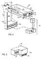
- the figure 4 shows in perspective an additive block able to communicate with parallel communication cables.
- the figure 5 shows in perspective a part of an additive block able to communicate with a two-wire bus.
- the motor starter device shown on the figure 1 comprises a multipole main apparatus 10, here composed of a main housing 11 which includes a pedestal 12 with electromechanical components, and an electronic block or module 20 with a protective function, removably attached to the base of the main housing.
- the motor starter device can be made differently, either in one piece, or with a circuit breaker block and a contactor block.
- the electromechanical base 12 comprises upstream power terminals 14a, to be connected to a power source, and downstream power terminals 14b, to be connected to a load such as a motor. Internal power lines with mechanical switch poles 15 connect the terminals 14a, 14b.
- a manual control knob 16 capable of taking at least one "on” position and a “off” position, acts via an opening and closing mechanism 17 on the moving contacts of the poles 15.
- the mechanical links are indicated by gray arrows on the figure 1 .
- the electronic protection unit 20 communicates by appropriate electrical connectors and conductors with a magnetic overcurrent release device 18 and with an electromagnet 19 for voluntary on-off control, the trigger 18 and the electromagnet 19 being located in the base 12.
- the protective block 20 has at the rear, towards a face 12a of the base 12 facing forward and hidden by the block when it is mounted, two connections 21 of supply and control of the coil of the electromagnet 19, in contact with complementary connections provided on the face 12a.
- An additive block 30 of mixed electromechanical / electronic type is interchangeably reported in a space below the electronic protection unit 20 and above a lower end 12c of the electromechanical base 12, between vertical wings 12d of the base . It comprises a housing 31 having a front face 31a, a rear face 31b, 31c and 31c high and 31c side faces, 31f. In the case where the motor starter apparatus would be made differently from what is shown, the additive block would be reported by insertion into a suitable housing.
- the connector 33 is intended to connect to power supply and external communication lines in bus or in sheet. It preferably includes power supply pins 33a (i.e., potential terminal V + and potential terminal 0V), signal input pins 33b, and signal output pins 33c. To the pins 33b may for example be input signals control signals determining a first or a second direction of operation; the pins 33c may for example be applied at the output of signals significant to the state of the poles, the state of the button, the triggered state of the device, etc.
- power supply pins 33a i.e., potential terminal V + and potential terminal 0V
- signal input pins 33b i.e., signal input pins 33b
- signal output pins 33c To the pins 33b may for example be input signals control signals determining a first or a second direction of operation; the pins 33c may for example be applied at the output of signals significant to the state of the poles, the state of the button, the triggered state of the device, etc.
- the connector 33 may advantageously be of the RJ45 type.
- the connection of the pins 35a of the output connector 35 with the main apparatus is effected differently depending on whether the apparatus is mounted in simple mode ( figure 1 ) - interconnection member 50 - or in inverter mode ( figure 3 ) - interconnecting body 51.
- two switches 37 located on two respective conductors connecting a supply input pin 33a of potential V + output pins O1 and O3 respectively.
- a supply input pin 33a of potential 0V is connected to the output pin O2.
- Two mechanical switches 38 located in the additive block 30 are biased by the mechanism 17 by means of actuating fingers 12f to switch, one according to the open or closed state of the power poles 15 of the apparatus, other depending on the state of the button 16 or the triggered state of the apparatus.
- an electrical connection 39 is established with the protection module 20, via appropriate contacts between the members 20 and 30, to deliver to the processing circuit 36, and thus to the bus connected to the pins 33c, more advanced status information, such as trigger intensity level, etc.
- the pins O1, O2, respectively at potentials V + and 0V are connected to input pins 12e of the base 12 of the device, while the pin O3 remains unconnected.
- the interconnection member 50 then provides the connection between the output pins O1, O2 of the additive and the input pins 12b of the device (see FIG. figure 4 ).
- the pins O1, O3 are connected to the input pin V + by respective switches 37 ensuring the exclusive power of one or the other depending on the desired direction of travel (direct or reverse), while pin O2 is connected to a grounding input of the inverter 40.
- This has a housing 41 having input pins 42 to be connected to the output pins O1, O2, O3 of the additive block and output pins 43 to connect to the input pins 12e of the base 12.
- the interconnection block 51 is then arranged to allow access to the screws of the downstream power terminals 14b of the apparatus.
- FIG. 5 An additive block allowing the connection to a two-wire bus, for example of the AS-i type, is illustrated by the figure 5 .
Landscapes
- Details Of Connecting Devices For Male And Female Coupling (AREA)
- Patch Boards (AREA)
- Coupling Device And Connection With Printed Circuit (AREA)
- Breakers (AREA)
- Keying Circuit Devices (AREA)
- Control Of Direct Current Motors (AREA)
- Relay Circuits (AREA)
- Vehicle Cleaning, Maintenance, Repair, Refitting, And Outriggers (AREA)
- Driving Mechanisms And Operating Circuits Of Arc-Extinguishing High-Tension Switches (AREA)
- Connections By Means Of Piercing Elements, Nuts, Or Screws (AREA)
- Multi-Conductor Connections (AREA)
Description
- La présente invention concerne un bloc additif de communication, susceptible d'être adjoint à un appareil électrique principal à contacts de puissance séparables, notamment àun appareil de départ-moteur du genre comprenant un électroaimant de commande de marche-arrêt, un dispositif de protection contre les défauts électriques et un organe de commande manuelle de marche-arrêt.
- Dans les appareils connus de ce type, notamment dans celui que décrit le document
WO 01/27 958 - Les blocs additifs de communication connus ne permettent pas de connecter de manière simple à l'appareil principal, soit un câblage classique de commande, soit un câblage de bus - notamment propre à un bus de terrain -, pour assurer une liaison de signalisation et de commande associée à l'appareil principal. De plus, ils ne permettent pas de redistribuer vers l'appareil principal des ordres de commande transitant par une telle liaison.
- L'invention a pour but de remédier à cet inconvénient.
- Selon l'invention, le boîtier du bloc additif présente sur sa face avant :
- des premières connexions, à fonction d'entrée-sortie, aptes à la connexion de conducteurs de communication, notamment de conducteurs de bus, assurant la liaison avec un dispositif externe de commande et de surveillance de l'appareil principal,
- des secondes connexions, à fonction de sortie, aptes à la connexion de conducteurs de liaison avec les bornes d'entrée de commande de l'appareil principal.
- Les connexions de liaison du bloc additif avec l'extérieur et celles qui redistribuent vers l'appareil principal les signaux de commande sont rassemblées sur la face avant du bloc additif ; les autres parois du bloc additif sont donc disponibles pour d'autres fonctions, notamment des fonctions de guidage du bloc dans le boîtier principal, et de connexion électrique et de dialogue mécanique avec l'appareil principal. L'ensemble formé par l'appareil principal et le bloc additif peut dès lors être conçu avec un encombrement réduit.
- Les premières connexions peuvent être des broches rassemblées dans un connecteur situé àl'avant du boîtier du bloc additif, et composées de broches d'entrée (àfonction de commande de l'appareil principal), ainsi que de broches de sortie (àfonction de signalisation de l'état de l'appareil principal). Les premières connexions peuvent comprendre des connexions d'alimentation, notamment pour un circuit électronique de traitement situé dans le bloc additif ou un organe inverseur.
- Les secondes connexions sont avantageusement au nombre de trois, deux connexions étant affectées à un signal de marche-arrêt de l'appareil et la troisième connexion à un signal d'inversion de sens de marche de l'appareil.
- Le bloc additif peut comprendre à l'arrière au moins un organe interrupteur apte à coopérer mécaniquement avec un organe mécanique menant situé dans l'appareil principal et dont le mouvement traduit un changement d'état de cet appareil.
- La description détaillée qui suit, avec référence à un mode de réalisation donné àtitre d'exemple et représenté par les dessins annexés, permettra d'expliciter l'invention.
- La
figure 1 représente schématiquement un appareil de départ-moteur équipé du bloc additif selon l'invention. - La
figure 2 est une vue schématique du même appareil, présentant une composition qui permet l'inversion de sens de marche du moteur. - La
figure 3 est le schéma d'un exemple de réalisation d'un bloc additif. - La
figure 4 montre en perspective un bloc additif apte àcommuniquer avec des câbles de communication parallèles. - La
figure 5 montre en perspective une partie d'un bloc additif apte à communiquer avec un bus bifilaire. - L'appareil de départ-moteur illustré sur la
figure 1 comprend un appareil principal multipolaire 10, ici composé d'un boîtier principal 11 qui inclut un socle 12 à constituants électromécaniques, et un bloc ou module électronique 20 à fonction de protection, fixé de manière amovible au socle du boîtier principal. L'appareil de départ-moteur peut être constitué différemment, soit de manière monobloc, soit avec un bloc disjoncteur et un bloc contacteur. - Le socle électromécanique 12 comporte des bornes de puissance amont 14a, à relier à une source d'alimentation, et des bornes de puissance aval 14b, à relier à une charge telle qu'un moteur. Des lignes de puissance internes dotées de pôles interrupteurs mécaniques 15 relient les bornes 14a, 14b. Un bouton de commande manuelle 16, capable de prendre au moins une position "marche" et une position "arrêt", agit par l'intermédiaire d'un mécanisme d'ouverture et fermeture 17 sur les contacts mobiles des pôles 15. Les liaisons mécaniques sont indiquées par des flèches en grisé sur la
figure 1 . - Le bloc électronique de protection 20 communique par des connecteurs et conducteurs électriques appropriés avec un déclencheur magnétique de surintensité 18 et avec un électroaimant 19 de commande volontaire de marche-arrêt, le déclencheur 18 et l'électroaimant 19 étant situés dans le socle 12. En particulier, le bloc de protection 20 présente à l'arrière, vers une face 12a du socle 12 orientée vers l'avant et cachée par le bloc quand il est monté, deux connexions 21 d'alimentation et de commande de la bobine de l'électroaimant 19, au contact de connexions complémentaires prévues sur la face 12a.
- Un bloc additif 30 de type mixte électromécanique/électronique est rapporté de façon interchangeable dans un espace situé au-dessous du bloc électronique de protection 20 et au-dessus d'une avancée inférieure 12c du socle électromécanique 12, entre des ailes verticales 12d du socle. Il comprend un boîtier 31 présentant une face avant 31 a, une face arrière 31 b, des faces haute 31 c et basse 31d et latérales 31e,31f. Dans le cas où l'appareil de départ-moteur serait réalisé différemment de ce qui est représenté, le bloc additif serait rapporté par insertion dans un logement adéquat.
- Dans la face avant 31 a du bloc additif 30 sont prévues (voir
figure 4 ) une ouverture 32 pour un connecteur multibroches 33 d'entrée-sortie et une ouverture 34 pour un connecteur 35 de sortie à trois broches 35a désignées par O1,O2,O3. Le connecteur 33 est destiné à se connecter à des conducteurs d'alimentation et de communication externe en bus ou en nappe. Il comprend de préférence des broches d'alimentation 33a (à savoir une borne de potentiel V+ et une borne de potentiel 0V), des broches d'entrée de signal 33b et des broches de sortie de signal 33c. Aux broches 33b peuvent par exemple être appliqués en entrée des signaux de commande déterminant un premier ou un deuxième sens de marche ; aux broches 33c peuvent par exemple être appliqués en sortie des signaux significatifs de l'état des pôles, de l'état du bouton, de l'état déclenché de l'appareil, etc. Dans la forme d'exécution représentée, le connecteur 33 peut avantageusement être du type RJ45. La liaison des broches 35a du connecteur de sortie 35 avec l'appareil principal s'effectue différemment suivant que l'appareil est monté en mode simple (figure 1 ) - organe d'interconnexion 50 - ou en mode inverseur (figure 3 )- organe d'interconnexion 51. - Au circuit de traitement 36 du bloc additif 30 sont associés dans ce bloc deux interrupteurs 37 situés sur deux conducteurs respectifs reliant une broche d'entrée d'alimentation 33a de potentiel V+ aux broches de sortie O1 et respectivement O3. D'autre part, une broche d'entrée d'alimentation 33a de potentiel 0V est reliée à la broche de sortie O2. Deux interrupteurs mécaniques 38 situés dans le bloc additif 30 sont sollicités par le mécanisme 17 au moyen de doigts d'actionnement 12f pour commuter, l'un en fonction de l'état ouvert ou fermé des pôles de puissance 15 de l'appareil, l'autre en fonction de l'état du bouton 16 ou de l'état déclenché de l'appareil. Dans une variante de réalisation, une liaison électrique 39 est établie avec le module de protection 20, par le biais de contacts appropriés entre les organes 20 et 30, pour livrer au circuit de traitement 36, et donc au bus relié aux broches 33c, des informations d'état plus évoluées, telles que le niveau d'intensité de déclenchement, etc..
- Dans un mode de réalisation simple, c'est-à-dire sans inverseur (
figure 1 ), les broches O1,O2, respectivement aux potentiels V+ et 0V, sont reliées à des broches d'entrée 12e du socle 12 de l'appareil, tandis que la broche O3 reste non connectée. L'organe d'interconnexion 50 assure alors la connexion entre les broches de sortie 35 O1,O2 de l'additif et les broches d'entrée 12b de l'appareil (voirfigure 4 ). - Dans un mode de réalisation avec inverseur 40 (
figure 3 ), les broches O1,O3 sont reliées à la broche d'entrée V+ par des interrupteurs respectifs 37 assurant la mise sous tension exclusive de l'une ou l'autre en fonction du sens de marche souhaité (direct ou inverse), tandis que la broche O2 est reliée à une entrée de mise à la terre de l'inverseur 40. Celui-ci présente un boîtier 41 doté de broches d'entrée 42 à connecter aux broches de sortie 35 O1,O2,O3 du bloc additif et de broches de sortie 43 à connecter aux broches d'entrée 12e du socle 12. Comme indiqué en 52, le bloc d'interconnexion 51 est alors agencé pour permettre l'accès aux vis des bornes de puissance aval 14b de l'appareil. - Un bloc additif permettant la connexion àun bus bifilaire, par exemple de type AS-i, est illustré par la
figure 5 .
Claims (5)
- Bloc additif accouplable à un appareil électrique principal à contacts de puissance séparables, et comprenant un boîtier doté notamment d'une face avant et d'une face arrière et rapporté frontalement contre ou dans l'appareil principal,
caractérisé par le fait que le boîtier (31) du bloc additif (30) présente sur sa face avant (31 a)- des premières connexions (33), à fonction d'entrée-sortie, aptes à la connexion de conducteurs de communication, notamment de conducteurs de bus, assurant la liaison avec un dispositif de commande et de surveillance de l'appareil principal,- des secondes connexions (35), à fonction de sortie, aptes à la connexion de conducteurs de liaison avec les bornes d'entrée de commande de l'appareil principal. - Bloc additif selon la revendication 1, caractérisé par le fait que les premières connexions (33) sont des broches rassemblées dans un connecteur situé à l'avant du boîtier du bloc additif, et comprennent des connexions d'entrée (33b) de commande de l'appareil principal, ainsi que des connexions (33c) de sortie de signalisation de l'état de l'appareil principal.
- Bloc additif selon la revendication 1, caractérisé par le fait que les premières connexions (33) sont rassemblées dans un connecteur avant du boîtier du bloc additif, et comprennent des connexions d'alimentation (33a) d'un circuit électronique de traitement (36).
- Bloc additif selon la revendication 1, caractérisé par le fait que les secondes connexions (35) sont au nombre de trois, deux connexions (O1,O2) étant affectées à un signal de marche-arrêt et la troisième connexion (03) à un signal d'inversion de sens de marche.
- Bloc additif selon la revendication 1, caractérisé par le fait que le bloc additif (30) comprend à l'opposé de la face avant (31a) au moins un organe interrupteur (38) apte à coopérer mécaniquement avec un organe mécanique menant situé dans l'appareil principal et dont le mouvement traduit un changement d'état de cet appareil.
Applications Claiming Priority (2)
| Application Number | Priority Date | Filing Date | Title |
|---|---|---|---|
| FR0203526 | 2002-03-19 | ||
| FR0203526A FR2837618B1 (fr) | 2002-03-19 | 2002-03-19 | Bloc additif pour contacteur-disjoncteur |
Publications (2)
| Publication Number | Publication Date |
|---|---|
| EP1347485A1 EP1347485A1 (fr) | 2003-09-24 |
| EP1347485B1 true EP1347485B1 (fr) | 2010-09-01 |
Family
ID=27772258
Family Applications (1)
| Application Number | Title | Priority Date | Filing Date |
|---|---|---|---|
| EP03100562A Expired - Lifetime EP1347485B1 (fr) | 2002-03-19 | 2003-03-07 | Bloc additif pour contacteur-disjoncteur. |
Country Status (8)
| Country | Link |
|---|---|
| US (1) | US6734380B2 (fr) |
| EP (1) | EP1347485B1 (fr) |
| JP (1) | JP4173386B2 (fr) |
| CN (1) | CN1320581C (fr) |
| AT (1) | ATE480002T1 (fr) |
| DE (1) | DE60333969D1 (fr) |
| ES (1) | ES2347541T3 (fr) |
| FR (1) | FR2837618B1 (fr) |
Families Citing this family (10)
| Publication number | Priority date | Publication date | Assignee | Title |
|---|---|---|---|---|
| US8116919B2 (en) * | 2004-08-10 | 2012-02-14 | Ellenberger & Poensgen Gmbh | Circuit breaker configuration |
| DE202004012469U1 (de) * | 2004-08-10 | 2006-01-19 | Ellenberger & Poensgen Gmbh | Schutzschalteranordnung |
| KR100844193B1 (ko) | 2006-10-13 | 2008-07-04 | (주)대 유 | 무기 및 영양성분의 식물체내 흡수 촉진제로서의 토르말린첨가제 및 토르말린을 함유한 복합비료 |
| US20140211345A1 (en) * | 2013-01-30 | 2014-07-31 | Eaton Corporation | Annunciating or power vending circuit breaker for an electric load |
| FR3007902B1 (fr) * | 2013-06-26 | 2015-07-24 | Schneider Electric Ind Sas | Dispositif amovible pour declencheur electronique, procede d'alimentation d'un tel dispositif et ensemble comportant un declencheur electronique et un tel dispositif amovible |
| US10032588B2 (en) * | 2013-09-24 | 2018-07-24 | Ford Global Technologies, Llc | Integrated high voltage contactor and service disconnect |
| US20170110281A1 (en) * | 2015-10-19 | 2017-04-20 | Eaton Corporation | Field-configurable interruption apparatus having individually selectable interruption portion and electronic portion |
| FR3069716B1 (fr) * | 2017-07-25 | 2019-09-06 | Schneider Electric Industries Sas | Dispositif electrique pour l'alimentation electrique d'appareils electriques de puissance |
| BR112021006387A2 (pt) * | 2018-10-04 | 2021-07-06 | Weg Drives & Controls Automacao Ltda | módulo auxiliar para contator eletromagnético |
| US11515691B2 (en) * | 2020-09-30 | 2022-11-29 | Rockwell Automation Switzerland Gmbh | Modular low voltage power distribution module |
Family Cites Families (5)
| Publication number | Priority date | Publication date | Assignee | Title |
|---|---|---|---|---|
| FR2772203B1 (fr) * | 1997-12-09 | 2000-01-21 | Schneider Electric Sa | Dispositif d'interruption electrique comportant un module de communication |
| CA2269001C (fr) * | 1998-04-21 | 2008-07-15 | The Chamberlain Group, Inc. | Controleur automatique de mecanisme de fermeture de porte |
| US6262872B1 (en) * | 1999-06-03 | 2001-07-17 | General Electric Company | Electronic trip unit with user-adjustable sensitivity to current spikes |
| FR2799572B1 (fr) * | 1999-10-11 | 2001-12-21 | Schneider Electric Ind Sa | Contacteur-disjoncteur |
| US6429659B1 (en) * | 2000-03-09 | 2002-08-06 | General Electric Company | Connection tester for an electronic trip unit |
-
2002
- 2002-03-19 FR FR0203526A patent/FR2837618B1/fr not_active Expired - Fee Related
-
2003
- 2003-03-07 DE DE60333969T patent/DE60333969D1/de not_active Expired - Lifetime
- 2003-03-07 ES ES03100562T patent/ES2347541T3/es not_active Expired - Lifetime
- 2003-03-07 AT AT03100562T patent/ATE480002T1/de not_active IP Right Cessation
- 2003-03-07 US US10/383,065 patent/US6734380B2/en not_active Expired - Lifetime
- 2003-03-07 EP EP03100562A patent/EP1347485B1/fr not_active Expired - Lifetime
- 2003-03-12 JP JP2003067018A patent/JP4173386B2/ja not_active Expired - Lifetime
- 2003-03-18 CN CNB031204627A patent/CN1320581C/zh not_active Expired - Lifetime
Also Published As
| Publication number | Publication date |
|---|---|
| EP1347485A1 (fr) | 2003-09-24 |
| CN1445808A (zh) | 2003-10-01 |
| CN1320581C (zh) | 2007-06-06 |
| DE60333969D1 (de) | 2010-10-14 |
| FR2837618B1 (fr) | 2004-05-28 |
| ES2347541T3 (es) | 2010-11-02 |
| US20030178292A1 (en) | 2003-09-25 |
| FR2837618A1 (fr) | 2003-09-26 |
| ATE480002T1 (de) | 2010-09-15 |
| JP4173386B2 (ja) | 2008-10-29 |
| JP2003297170A (ja) | 2003-10-17 |
| US6734380B2 (en) | 2004-05-11 |
Similar Documents
| Publication | Publication Date | Title |
|---|---|---|
| EP0736946B1 (fr) | Module d'interface entre un bus de terrain et un appareillage électrique de commande et de protection d'un moteur électrique | |
| CA2453792A1 (fr) | Disjoncteur de fuite de terre sans contact a chevauchement permettant de bloquer automatiquement l'ouverture frontale d'une prise protegee lorsqu'il se declenche | |
| CA2558297A1 (fr) | Dispositifs de cablage electrique munis d'un obturateur de protection | |
| FR2406932A1 (fr) | Arrangement de connecteur electrique pour interconnecter plusieurs stations eloignees d'emission de signaux a un terminal de traitement central | |
| EP0923185B1 (fr) | Dispositif d'interruption électrique comportant un module de communication | |
| EP1347485A1 (fr) | Bloc additif pour contacteur-disjoncteur. | |
| EP1181704B1 (fr) | Relais de protection et ensemble de commande protege a cablage frontal | |
| EP1318537B1 (fr) | Ensemble d'appareils électriques pour la commande d'appareils de puissance | |
| FR2827703A1 (fr) | Appareil interrupteur multipolaire de type contacteur-disjoncteur | |
| EP0112740A1 (fr) | Circuit électronique de commande d'un appareillage à fonctionnement multiple équipé d'un mécanisme à électro-aimant | |
| FR2631717A1 (fr) | Systeme et dispositif de commande pour appareil contacteur | |
| EP0420058B1 (fr) | Système de prises électriques de sécurité | |
| US10686284B2 (en) | Power over ethernet connection with power control | |
| EP1126568B1 (fr) | Ensemble de départ-moteur | |
| EP1517347B1 (fr) | Ensemble de départ-moteur à câblage de contrôle. | |
| EP0058589A1 (fr) | Adaptateur à interrupteur différentiel | |
| EP1376637A1 (fr) | Ensemble de protection et de commande électromagnétique. | |
| CH680960A5 (en) | Wall mounted power outlet socket - includes reed switch controlling live socket supply activated by magnet in plug | |
| EP4348692B1 (fr) | Ensemble comprenant un appareillage électronique de protection et un module de contacts | |
| WO2002065498A1 (fr) | Dispositif de depart moteur | |
| JP2506388Y2 (ja) | 開閉器 | |
| EP1263102B1 (fr) | Appareillage électrique de démarrage d'un moteur | |
| FR2652455A1 (fr) | Systeme de prises electriques de securite. | |
| FR2594592A1 (fr) | Appareil interrupteur a visualisation d'etat | |
| FR2757700A1 (fr) | Dispositif de protection et de raccordement d'un appareil electrique a une source de tension d'alimentation polyphasee |
Legal Events
| Date | Code | Title | Description |
|---|---|---|---|
| PUAI | Public reference made under article 153(3) epc to a published international application that has entered the european phase |
Free format text: ORIGINAL CODE: 0009012 |
|
| AK | Designated contracting states |
Kind code of ref document: A1 Designated state(s): AT BE BG CH CY CZ DE DK EE ES FI FR GB GR HU IE IT LI LU MC NL PT SE SI SK TR |
|
| AX | Request for extension of the european patent |
Extension state: AL LT LV MK RO |
|
| 17P | Request for examination filed |
Effective date: 20031010 |
|
| AKX | Designation fees paid |
Designated state(s): AT BE BG CH CY CZ DE DK EE ES FI FR GB GR HU IE IT LI LU MC NL PT SE SI SK TR |
|
| RAP1 | Party data changed (applicant data changed or rights of an application transferred) |
Owner name: SCHNEIDER ELECTRIC INDUSTRIES SAS |
|
| GRAP | Despatch of communication of intention to grant a patent |
Free format text: ORIGINAL CODE: EPIDOSNIGR1 |
|
| GRAS | Grant fee paid |
Free format text: ORIGINAL CODE: EPIDOSNIGR3 |
|
| RIN1 | Information on inventor provided before grant (corrected) |
Inventor name: HAUDRY, JEAN Inventor name: LECOMTE, RENE Inventor name: GERARD, ALAIN |
|
| GRAA | (expected) grant |
Free format text: ORIGINAL CODE: 0009210 |
|
| AK | Designated contracting states |
Kind code of ref document: B1 Designated state(s): AT BE BG CH CY CZ DE DK EE ES FI FR GB GR HU IE IT LI LU MC NL PT RO SE SI SK TR |
|
| REG | Reference to a national code |
Ref country code: GB Ref legal event code: FG4D Free format text: NOT ENGLISH |
|
| REG | Reference to a national code |
Ref country code: CH Ref legal event code: EP |
|
| REG | Reference to a national code |
Ref country code: IE Ref legal event code: FG4D Free format text: LANGUAGE OF EP DOCUMENT: FRENCH |
|
| REF | Corresponds to: |
Ref document number: 60333969 Country of ref document: DE Date of ref document: 20101014 Kind code of ref document: P |
|
| REG | Reference to a national code |
Ref country code: SE Ref legal event code: TRGR Ref country code: ES Ref legal event code: FG2A Ref document number: 2347541 Country of ref document: ES Kind code of ref document: T3 |
|
| REG | Reference to a national code |
Ref country code: NL Ref legal event code: VDEP Effective date: 20100901 |
|
| PG25 | Lapsed in a contracting state [announced via postgrant information from national office to epo] |
Ref country code: FI Free format text: LAPSE BECAUSE OF FAILURE TO SUBMIT A TRANSLATION OF THE DESCRIPTION OR TO PAY THE FEE WITHIN THE PRESCRIBED TIME-LIMIT Effective date: 20100901 Ref country code: AT Free format text: LAPSE BECAUSE OF FAILURE TO SUBMIT A TRANSLATION OF THE DESCRIPTION OR TO PAY THE FEE WITHIN THE PRESCRIBED TIME-LIMIT Effective date: 20100901 |
|
| PG25 | Lapsed in a contracting state [announced via postgrant information from national office to epo] |
Ref country code: CY Free format text: LAPSE BECAUSE OF FAILURE TO SUBMIT A TRANSLATION OF THE DESCRIPTION OR TO PAY THE FEE WITHIN THE PRESCRIBED TIME-LIMIT Effective date: 20100901 Ref country code: SI Free format text: LAPSE BECAUSE OF FAILURE TO SUBMIT A TRANSLATION OF THE DESCRIPTION OR TO PAY THE FEE WITHIN THE PRESCRIBED TIME-LIMIT Effective date: 20100901 |
|
| REG | Reference to a national code |
Ref country code: IE Ref legal event code: FD4D |
|
| PG25 | Lapsed in a contracting state [announced via postgrant information from national office to epo] |
Ref country code: GR Free format text: LAPSE BECAUSE OF FAILURE TO SUBMIT A TRANSLATION OF THE DESCRIPTION OR TO PAY THE FEE WITHIN THE PRESCRIBED TIME-LIMIT Effective date: 20101202 Ref country code: NL Free format text: LAPSE BECAUSE OF FAILURE TO SUBMIT A TRANSLATION OF THE DESCRIPTION OR TO PAY THE FEE WITHIN THE PRESCRIBED TIME-LIMIT Effective date: 20100901 |
|
| PG25 | Lapsed in a contracting state [announced via postgrant information from national office to epo] |
Ref country code: IE Free format text: LAPSE BECAUSE OF FAILURE TO SUBMIT A TRANSLATION OF THE DESCRIPTION OR TO PAY THE FEE WITHIN THE PRESCRIBED TIME-LIMIT Effective date: 20100901 |
|
| PG25 | Lapsed in a contracting state [announced via postgrant information from national office to epo] |
Ref country code: EE Free format text: LAPSE BECAUSE OF FAILURE TO SUBMIT A TRANSLATION OF THE DESCRIPTION OR TO PAY THE FEE WITHIN THE PRESCRIBED TIME-LIMIT Effective date: 20100901 Ref country code: SK Free format text: LAPSE BECAUSE OF FAILURE TO SUBMIT A TRANSLATION OF THE DESCRIPTION OR TO PAY THE FEE WITHIN THE PRESCRIBED TIME-LIMIT Effective date: 20100901 Ref country code: PT Free format text: LAPSE BECAUSE OF FAILURE TO SUBMIT A TRANSLATION OF THE DESCRIPTION OR TO PAY THE FEE WITHIN THE PRESCRIBED TIME-LIMIT Effective date: 20110103 Ref country code: CZ Free format text: LAPSE BECAUSE OF FAILURE TO SUBMIT A TRANSLATION OF THE DESCRIPTION OR TO PAY THE FEE WITHIN THE PRESCRIBED TIME-LIMIT Effective date: 20100901 Ref country code: RO Free format text: LAPSE BECAUSE OF FAILURE TO SUBMIT A TRANSLATION OF THE DESCRIPTION OR TO PAY THE FEE WITHIN THE PRESCRIBED TIME-LIMIT Effective date: 20100901 |
|
| PLBE | No opposition filed within time limit |
Free format text: ORIGINAL CODE: 0009261 |
|
| STAA | Information on the status of an ep patent application or granted ep patent |
Free format text: STATUS: NO OPPOSITION FILED WITHIN TIME LIMIT |
|
| 26N | No opposition filed |
Effective date: 20110606 |
|
| PG25 | Lapsed in a contracting state [announced via postgrant information from national office to epo] |
Ref country code: DK Free format text: LAPSE BECAUSE OF FAILURE TO SUBMIT A TRANSLATION OF THE DESCRIPTION OR TO PAY THE FEE WITHIN THE PRESCRIBED TIME-LIMIT Effective date: 20100901 |
|
| BERE | Be: lapsed |
Owner name: SCHNEIDER ELECTRIC INDUSTRIES SAS Effective date: 20110331 |
|
| REG | Reference to a national code |
Ref country code: DE Ref legal event code: R097 Ref document number: 60333969 Country of ref document: DE Effective date: 20110606 |
|
| PG25 | Lapsed in a contracting state [announced via postgrant information from national office to epo] |
Ref country code: MC Free format text: LAPSE BECAUSE OF NON-PAYMENT OF DUE FEES Effective date: 20110331 |
|
| REG | Reference to a national code |
Ref country code: CH Ref legal event code: PL |
|
| GBPC | Gb: european patent ceased through non-payment of renewal fee |
Effective date: 20110307 |
|
| PG25 | Lapsed in a contracting state [announced via postgrant information from national office to epo] |
Ref country code: BE Free format text: LAPSE BECAUSE OF NON-PAYMENT OF DUE FEES Effective date: 20110331 |
|
| PG25 | Lapsed in a contracting state [announced via postgrant information from national office to epo] |
Ref country code: LI Free format text: LAPSE BECAUSE OF NON-PAYMENT OF DUE FEES Effective date: 20110331 Ref country code: CH Free format text: LAPSE BECAUSE OF NON-PAYMENT OF DUE FEES Effective date: 20110331 |
|
| PG25 | Lapsed in a contracting state [announced via postgrant information from national office to epo] |
Ref country code: GB Free format text: LAPSE BECAUSE OF NON-PAYMENT OF DUE FEES Effective date: 20110307 |
|
| PG25 | Lapsed in a contracting state [announced via postgrant information from national office to epo] |
Ref country code: LU Free format text: LAPSE BECAUSE OF NON-PAYMENT OF DUE FEES Effective date: 20110307 |
|
| PG25 | Lapsed in a contracting state [announced via postgrant information from national office to epo] |
Ref country code: BG Free format text: LAPSE BECAUSE OF FAILURE TO SUBMIT A TRANSLATION OF THE DESCRIPTION OR TO PAY THE FEE WITHIN THE PRESCRIBED TIME-LIMIT Effective date: 20101201 Ref country code: TR Free format text: LAPSE BECAUSE OF FAILURE TO SUBMIT A TRANSLATION OF THE DESCRIPTION OR TO PAY THE FEE WITHIN THE PRESCRIBED TIME-LIMIT Effective date: 20100901 |
|
| PG25 | Lapsed in a contracting state [announced via postgrant information from national office to epo] |
Ref country code: HU Free format text: LAPSE BECAUSE OF FAILURE TO SUBMIT A TRANSLATION OF THE DESCRIPTION OR TO PAY THE FEE WITHIN THE PRESCRIBED TIME-LIMIT Effective date: 20100901 |
|
| REG | Reference to a national code |
Ref country code: FR Ref legal event code: PLFP Year of fee payment: 14 |
|
| REG | Reference to a national code |
Ref country code: FR Ref legal event code: PLFP Year of fee payment: 15 |
|
| REG | Reference to a national code |
Ref country code: DE Ref legal event code: R084 Ref document number: 60333969 Country of ref document: DE |
|
| REG | Reference to a national code |
Ref country code: FR Ref legal event code: PLFP Year of fee payment: 16 |
|
| PGFP | Annual fee paid to national office [announced via postgrant information from national office to epo] |
Ref country code: DE Payment date: 20220329 Year of fee payment: 20 |
|
| PGFP | Annual fee paid to national office [announced via postgrant information from national office to epo] |
Ref country code: SE Payment date: 20220324 Year of fee payment: 20 Ref country code: IT Payment date: 20220323 Year of fee payment: 20 Ref country code: FR Payment date: 20220325 Year of fee payment: 20 |
|
| PGFP | Annual fee paid to national office [announced via postgrant information from national office to epo] |
Ref country code: ES Payment date: 20220418 Year of fee payment: 20 |
|
| REG | Reference to a national code |
Ref country code: DE Ref legal event code: R071 Ref document number: 60333969 Country of ref document: DE |
|
| REG | Reference to a national code |
Ref country code: ES Ref legal event code: FD2A Effective date: 20230427 |
|
| REG | Reference to a national code |
Ref country code: SE Ref legal event code: EUG |
|
| PG25 | Lapsed in a contracting state [announced via postgrant information from national office to epo] |
Ref country code: ES Free format text: LAPSE BECAUSE OF EXPIRATION OF PROTECTION Effective date: 20230308 |