EP1347189A2 - Logement de palier avec rainures et nervures axiales - Google Patents
Logement de palier avec rainures et nervures axiales Download PDFInfo
- Publication number
- EP1347189A2 EP1347189A2 EP03445036A EP03445036A EP1347189A2 EP 1347189 A2 EP1347189 A2 EP 1347189A2 EP 03445036 A EP03445036 A EP 03445036A EP 03445036 A EP03445036 A EP 03445036A EP 1347189 A2 EP1347189 A2 EP 1347189A2
- Authority
- EP
- European Patent Office
- Prior art keywords
- bearing
- seat
- component
- ring
- housing
- Prior art date
- Legal status (The legal status is an assumption and is not a legal conclusion. Google has not performed a legal analysis and makes no representation as to the accuracy of the status listed.)
- Withdrawn
Links
Images

Classifications
-
- F—MECHANICAL ENGINEERING; LIGHTING; HEATING; WEAPONS; BLASTING
- F16—ENGINEERING ELEMENTS AND UNITS; GENERAL MEASURES FOR PRODUCING AND MAINTAINING EFFECTIVE FUNCTIONING OF MACHINES OR INSTALLATIONS; THERMAL INSULATION IN GENERAL
- F16C—SHAFTS; FLEXIBLE SHAFTS; ELEMENTS OR CRANKSHAFT MECHANISMS; ROTARY BODIES OTHER THAN GEARING ELEMENTS; BEARINGS
- F16C35/00—Rigid support of bearing units; Housings, e.g. caps, covers
- F16C35/04—Rigid support of bearing units; Housings, e.g. caps, covers in the case of ball or roller bearings
- F16C35/06—Mounting or dismounting of ball or roller bearings; Fixing them onto shaft or in housing
- F16C35/07—Fixing them on the shaft or housing with interposition of an element
- F16C35/073—Fixing them on the shaft or housing with interposition of an element between shaft and inner race ring
-
- F—MECHANICAL ENGINEERING; LIGHTING; HEATING; WEAPONS; BLASTING
- F16—ENGINEERING ELEMENTS AND UNITS; GENERAL MEASURES FOR PRODUCING AND MAINTAINING EFFECTIVE FUNCTIONING OF MACHINES OR INSTALLATIONS; THERMAL INSULATION IN GENERAL
- F16C—SHAFTS; FLEXIBLE SHAFTS; ELEMENTS OR CRANKSHAFT MECHANISMS; ROTARY BODIES OTHER THAN GEARING ELEMENTS; BEARINGS
- F16C35/00—Rigid support of bearing units; Housings, e.g. caps, covers
- F16C35/04—Rigid support of bearing units; Housings, e.g. caps, covers in the case of ball or roller bearings
- F16C35/06—Mounting or dismounting of ball or roller bearings; Fixing them onto shaft or in housing
- F16C35/067—Fixing them in a housing
-
- F—MECHANICAL ENGINEERING; LIGHTING; HEATING; WEAPONS; BLASTING
- F16—ENGINEERING ELEMENTS AND UNITS; GENERAL MEASURES FOR PRODUCING AND MAINTAINING EFFECTIVE FUNCTIONING OF MACHINES OR INSTALLATIONS; THERMAL INSULATION IN GENERAL
- F16C—SHAFTS; FLEXIBLE SHAFTS; ELEMENTS OR CRANKSHAFT MECHANISMS; ROTARY BODIES OTHER THAN GEARING ELEMENTS; BEARINGS
- F16C19/00—Bearings with rolling contact, for exclusively rotary movement
- F16C19/02—Bearings with rolling contact, for exclusively rotary movement with bearing balls essentially of the same size in one or more circular rows
- F16C19/04—Bearings with rolling contact, for exclusively rotary movement with bearing balls essentially of the same size in one or more circular rows for radial load mainly
- F16C19/06—Bearings with rolling contact, for exclusively rotary movement with bearing balls essentially of the same size in one or more circular rows for radial load mainly with a single row or balls
Definitions
- the present invention refers to an improved bearing seat provided in or on a cylindrical surface of a component to which the bearing shall be mounted.
- Bearings are commonly used in combination with different types of bearing housings, or other components wherein the bearing is mounted in or on a seat in the housing or component, in such a manner that it shall be retained in the mounted position without being able to rotate in relation to the seat. It is often also desired that the bearing ring or rings shall not be axially movable in or on the seat unless subjected to intentional dismounting measures.
- Different types of attachment means have earlier been used for effecting such retainment of the bearing, such as tapering adapter sleeves and the like, which however mean increased number of components in the bearing assembly and therefore increased costs, and it also has been used interference fits, whereby is required close manufacturing tolerances and especial mounting and dismounting appliances and/or tools. Such accurate machining of the components require an increased manufacturing cost and the need of mounting and dismounting appliances and tools will also increase the handling work and thereby also the costs.
- the purpose of the present invention is to provide an improved bearing seat, by which the bearing can be mounted in the seat in a simple and efficient manner, without the need for close manufacturing tolerances and without aid of additional appliances, and this has been achieved in that the component in or on which the bearing seat is provided, at least in the surface region is softer than the bearing ring to be interconnected to the component via the seat, and that either one of seat and bearing ring in their surfaces facing each other has a number of irregularities arranged under a mutual axial mounting motion between the seat and the bearing ring to cause a deformation to the softer surface region, thereby forming a mutual grip between the seat and the bearing ring.
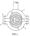
- Fig. 1 shows schematically a side view of a bearing to be mounted in a split component forming two cooperating bearing seat portions in accordance with the invention.
- Fig. 2 shows schematically an embodiment of the invention, wherein is shown an upper half of a bearing fitted to a shaft and mounted in a simple housing in accordance with the invention.
- Fig. 3 is a schematic end view cross-section of a one-piece cylindrical bearing housing and a bearing (shown as a circular member) positioned herein in accordance with the invention.
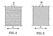
- Figs. 4 and 5 represent schematic views of different surface textures of at least one of the cooperating surfaces of the bearing and component to which the bearing shall be interconnected, and
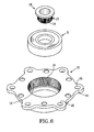
- Fig. 6 finally shows in an exploded perspective view a bearing and an inner and an outer component to which the bearing shall be mounted in accordance with the invention.
- Fig. 1 shows schematically a side view of a bearing housing comprising an upper and a lower, substantially semi-spherical bearing housing half 1, 2, which are intended to be interconnected by means of bolts 3 or the like, arranged to pass through bores in lugs 4 projecting radially outwards from the open edges of the semi-spherical bearing housing halves 1, 2.
- the split bearing housing is enclosing a bearing 5, shown as a ball bearing, but which can be any type of standard rolling or sliding bearing.
- At least the internal surfaces of the housing halves 1, 2 facing the bearing 5, are produced to have a lower hardness than the bearing, and they are also shaped with surface irregularities 6, preferably in form of grooves and ridges or serrations, extending substantially in the axial direction of the bearing 5.
- the housing halves 1, 2 are preferably made as sintered press bodies of metal powder, but they might also be manufactured as bodies of cast material, e.g. from aluminium or other alloys or materials being softer than the material of the bearing ring.
- Fig. 1 the two bearing housing halves 1, 2 are shown with a certain mutual distance in order better to illustrate the relation between the components.
- the bolt joints 3 or the like are tightened, thus that the gap between the lugs 4 of the housing halves 1 and 2 is eliminated, and the lugs 4 are in close contact with each other, the irregularities 6 or ridges have been brought in close contact with the harder material of the outer race ring of the bearing 5, whereby the irregularities have been deformed thus that the softer material will embrace the bearing and keep it in mounted position, thereby preventing it from making rotational movements in the bearing housing as well as axial motions in the housing, until a displacement force required for further deforming the softer material intentionally has been applied to the bearing for allowing it to be dismounted.
- Fig. 1 also shows that the axes A1, A2, A5 of the different components 1, 2, 5 might be offset from each other, whereby the deformation of the softer material will compensate for such initial misalignments to a certain degree.
- This also means that the requirements for manufacturing tolerances can be kept at a comparatively low level, when it comes to the manufacture of the bearing housing halves, and it also implies that it even is possible to use bearings, which due to certain outer ring defects otherwise would have been rejected, as some of those defects can be compensated by the deformation of the softer material during the mounting operation.
- Fig. 2 is shown in a side view a portion of a shaft 7 and in cross-section one half of a ball bearing 5 mounted with its inner ring on the shaft 7, against a shoulder 8 and having a simple, cup-shaped housing 9 (only half portion shown) in which the outer ring of the bearing 5 is mounted.
- the seat in the housing 9 is of a softer material than the bearing 5 itself, and the outer envelope surface of the outer ring of the bearing has preferably a number of surface irregularities 6 extending substantially in the axial direction, although it is also possible that the surface irregularities extend at an angle to the axial direction, and the irregularities might even be provided in the inner envelope surface of the housing itself.
- the housing 9 in this case is shaped as a one-piece cup, it can not be interconnected with the bearing in the same manner as in the embodiment according to Fig. 1, where the two halves of the two-piece housing are mounted around the bearing by being tightened against each other in radial direction, thereby causing a deformation of the softer material, required for creating a firm grip between the bearing and the seat. Therefore in the embodiment shown in Fig. 2, the bearing 5 has to be pushed axially into the housing (or vice versa), whereby the surface irregularities 6 cause a deformation of the softer material, either the irregularities are provided in the surface of the housing or in the bearing. Even in this case the bearing will be securely arrested against rotating in the seat of the housing 9, although the grip preventing against axial displacement in the housing is somewhat less effective as compared to the embodiment according to Fig. 1, where the material deforming force is applied radially.
- Fig. 3 shows in a schematic end view an external, one-piece housing, which is shown in two different embodiments 10a, above the horizontal and 10b below, and which differ slightly.
- a bearing 11a, 11b (for the sake of simplicity here shown only as a circular surface) is inserted in the housing 10a, 10b.
- the outer envelope surface of the outer ring of the bearing 11a is provided with a plurality of substantially axially extending surface irregularities 6a in form of grooves and ridges, serrations, splines or the like, which, when the bearing 11a is pushed axially into the housing 10a, will cut grooves in the softer material of the inner envelope surface, thereby causing a deformation of this material, which will create a grip between the bearing and the housing, primarily preventing rotation of the bearing in the seat in the housing 10a.
- Fig. 3 In the lower half of Fig. 3 is shown how the seat in the bearing housing 10b is provided with inwardly projecting irregularities 6b, extending primarily in axial direction and thereby being subjected to an axial force when the bearing 11b with its harder outer ring, is pushed into the seat in the housing 10b.
- This axial force will cause the softer material in the inner envelope surface of the bearing housing 10b to be deformed when the bearing is pushed in, thereby creating a grip, retaining the bearing in the mounted position in the seat until a bigger axial force is applied for continuing the deformation of the material in the softer surface portion, thereby releasing the grip.
- Fig. 4 shows in a planar view an example of the shape of the surface irregularities 6c in the inner or outer envelope surface of the seat in the housing or the bearing ring, and in this embodiment the surface is covered with a large number of serrations or splines extending truly axially along the surface (axial direction marked A).
- Fig. 5 shows in a view similar to Fig. 4 another example of the shape if the surface irregularities 6d, which here are shown to extend slightly inclined to the axial direction (A) of the envelope surface.
- Fig. 6 shows finally in an exploded perspective view a sealed bearing 5 intended for mounting with its outer ring in a seat 12 in the inner envelope surface of an external bearing housing 13, which, in the embodiment shown, is designed with external flanges 14 with attachment holes 15 for attachment of the housing to a machine part or an implement of any appropriate type.
- the seat 12 is equipped with axially extending surface irregularities 16 or serrations, which act as the surface irregularities 6 mentioned and described in connection to the earlier described embodiments of the invention.
- the housing 13 has a rather complex shape, but it can preferably be manufactured as a component in the form of a sintered powder pressed body, whereby the component can be obtained with a minimum of machining.
- the material in the bearing housing 13 is softer than that of the bearing rings themselves, and when pushed in axially, the bearing 5 therefore will cause deformation to the surface irregularities 16 in the seat 12, thereby arresting the bearing in the bearing housing 13, particularly against rotation in the seat.
- a seat 17 can be provided for the bearing 5 at the outer envelope surface of a sleeve 18, which can be used as a shaft journal or a connection to another part of a non-rotating of rotating machine member.
- the sleeve 18 is preferably - but not necessarily - made from a sintered press body, and has a lower hardness than the bearing rings.
- the seat 17 on the outer envelope surface of the sleeve 18 is provided with axially extending surface irregularities 19, which due to the lower hardness of the sleeve will be deformed when pushed into the bearing 5, thus generating a firm grip between bearing and sleeve, which however can be released by additional forces acting in the opposite direction and causing a further deformation of the softer material.
Landscapes
- Engineering & Computer Science (AREA)
- General Engineering & Computer Science (AREA)
- Mechanical Engineering (AREA)
- Mounting Of Bearings Or Others (AREA)
- Support Of The Bearing (AREA)
- Rolling Contact Bearings (AREA)
- Sliding-Contact Bearings (AREA)
Applications Claiming Priority (2)
| Application Number | Priority Date | Filing Date | Title |
|---|---|---|---|
| SE0200884 | 2002-03-20 | ||
| SE0200884A SE524350C2 (sv) | 2002-03-20 | 2002-03-20 | Ett förbättrat lagersäte |
Publications (2)
| Publication Number | Publication Date |
|---|---|
| EP1347189A2 true EP1347189A2 (fr) | 2003-09-24 |
| EP1347189A3 EP1347189A3 (fr) | 2005-06-29 |
Family
ID=20287363
Family Applications (1)
| Application Number | Title | Priority Date | Filing Date |
|---|---|---|---|
| EP03445036A Withdrawn EP1347189A3 (fr) | 2002-03-20 | 2003-03-18 | Logement de palier avec rainures et nervures axiales |
Country Status (3)
| Country | Link |
|---|---|
| US (1) | US20030210841A1 (fr) |
| EP (1) | EP1347189A3 (fr) |
| SE (1) | SE524350C2 (fr) |
Cited By (4)
| Publication number | Priority date | Publication date | Assignee | Title |
|---|---|---|---|---|
| WO2007141272A1 (fr) * | 2006-06-08 | 2007-12-13 | Vorwerk & Co. Interholding Gmbh | Procédé de connexion fixe en rotation d'un arbre et d'un moyeu ainsi que moyeu connecté par engagement de friction à un arbre |
| WO2008037368A1 (fr) | 2006-09-26 | 2008-04-03 | Aktiebolaget Skf | Unité pour porter des arbres de roues motrices de karts |
| EP2940331A1 (fr) * | 2014-05-02 | 2015-11-04 | Schaublin SA | Pallier ayant une interférence de course externe de palier aménageable dans une gamme de tailles d'alésage de logement |
| DE102004006660B4 (de) * | 2004-02-11 | 2016-09-22 | Man Truck & Bus Ag | Lagerbohrung zur Lagerung asymmetrisch belasteter Wellen und Achsen |
Families Citing this family (5)
| Publication number | Priority date | Publication date | Assignee | Title |
|---|---|---|---|---|
| US7385326B2 (en) * | 2005-12-29 | 2008-06-10 | Robert Bosch Gmbh | Motor plate |
| DE102016211694B3 (de) * | 2016-06-29 | 2017-10-05 | Ford Global Technologies, Llc | Getriebeeinheit für ein Kraftfahrzeug |
| US10233972B1 (en) * | 2017-09-08 | 2019-03-19 | GM Global Technology Operations LLC | Bearing race with serrations |
| JP6989062B1 (ja) * | 2020-02-07 | 2022-01-05 | 日本精工株式会社 | 転がり軸受の製造方法 |
| CN113464569B (zh) * | 2021-08-20 | 2022-05-17 | 盐城支点机械制造有限公司 | 一种新结构轧钢机用四列圆锥滚子轴承用轴承座 |
Citations (10)
| Publication number | Priority date | Publication date | Assignee | Title |
|---|---|---|---|---|
| US2581958A (en) * | 1945-07-12 | 1952-01-08 | Hoover Co | Antifriction bearing |
| GB833591A (en) * | 1956-10-04 | 1960-04-27 | Skf Svenska Kullagerfab Ab | Improvements relating to roller bearings and seatings therefor |
| FR1372802A (fr) * | 1963-10-02 | 1964-09-18 | Schaeffler Ohg Industriewerk | Palier à roulement |
| US3897988A (en) * | 1974-02-22 | 1975-08-05 | Textron Inc | Bearing for a conveyor roll or the like |
| US4094559A (en) * | 1976-12-30 | 1978-06-13 | Textron Inc. | Flanged bearing cartridge |
| GB2012010A (en) * | 1978-01-07 | 1979-07-18 | Kuhbier Gmbh & Co | Bearing housing |
| US4228210A (en) * | 1978-01-30 | 1980-10-14 | Trw Inc. | Plate or the like with serrated opening |
| EP0287296A2 (fr) * | 1987-04-13 | 1988-10-19 | Ishikawajima-Harima Jukogyo Kabushiki Kaisha | Construction de palier céramique |
| EP0875686A1 (fr) * | 1997-04-02 | 1998-11-04 | SKF Industrial Trading & Development Company, B.V. | Dispositif de palier avec montage à force |
| EP0926365A2 (fr) * | 1997-12-23 | 1999-06-30 | M.G. - MINI GEARS S.p.A. | Support de palier à autoréglage |
Family Cites Families (12)
| Publication number | Priority date | Publication date | Assignee | Title |
|---|---|---|---|---|
| US392085A (en) * | 1888-10-30 | Baling-press | ||
| US2147343A (en) * | 1937-11-05 | 1939-02-14 | Eidco Inc | Friction joint |
| US2620243A (en) * | 1950-05-20 | 1952-12-02 | Manor Die Cast Corp | Antifriction bearing assembly |
| US2779641A (en) * | 1954-10-20 | 1957-01-29 | Walter S Sutowski | Bearing construction |
| US3405982A (en) * | 1965-12-23 | 1968-10-15 | Fafnir Bearing Co | Self-anchoring bearing |
| DE3131000A1 (de) * | 1981-08-05 | 1983-02-24 | Uni-Cardan Ag, 5200 Siegburg | Kreuzgelenk |
| DE3216958C3 (de) * | 1982-05-06 | 1995-04-20 | Kugelfischer G Schaefer & Co | Befestigung einer Tretlagerwelle |
| US4671680A (en) * | 1983-06-23 | 1987-06-09 | Mtd Products Inc. | Bearing journal |
| US4741091A (en) * | 1986-08-12 | 1988-05-03 | Dayco Products-Eaglemotive, Inc. | Clutch for a cooling fan of a motor vehicle and method of making the same |
| DE3931447A1 (de) * | 1989-09-21 | 1991-04-04 | Skf Gmbh | Anordnung zur axialen lagesicherung eines waelzlagerringes |
| DE3840869C2 (de) * | 1988-12-03 | 1997-08-14 | Skf Gmbh | Anordnung zur Befestigung eines harten Lagerringes in der Bohrungsfläche eines Gehäuses oder auf der Mantelfläche eines Zapfens |
| US5439299A (en) * | 1995-01-13 | 1995-08-08 | Havens; Dale I. | Self-adjusting bearing support |
-
2002
- 2002-03-20 SE SE0200884A patent/SE524350C2/sv not_active IP Right Cessation
-
2003
- 2003-03-18 EP EP03445036A patent/EP1347189A3/fr not_active Withdrawn
- 2003-03-20 US US10/392,086 patent/US20030210841A1/en not_active Abandoned
Patent Citations (10)
| Publication number | Priority date | Publication date | Assignee | Title |
|---|---|---|---|---|
| US2581958A (en) * | 1945-07-12 | 1952-01-08 | Hoover Co | Antifriction bearing |
| GB833591A (en) * | 1956-10-04 | 1960-04-27 | Skf Svenska Kullagerfab Ab | Improvements relating to roller bearings and seatings therefor |
| FR1372802A (fr) * | 1963-10-02 | 1964-09-18 | Schaeffler Ohg Industriewerk | Palier à roulement |
| US3897988A (en) * | 1974-02-22 | 1975-08-05 | Textron Inc | Bearing for a conveyor roll or the like |
| US4094559A (en) * | 1976-12-30 | 1978-06-13 | Textron Inc. | Flanged bearing cartridge |
| GB2012010A (en) * | 1978-01-07 | 1979-07-18 | Kuhbier Gmbh & Co | Bearing housing |
| US4228210A (en) * | 1978-01-30 | 1980-10-14 | Trw Inc. | Plate or the like with serrated opening |
| EP0287296A2 (fr) * | 1987-04-13 | 1988-10-19 | Ishikawajima-Harima Jukogyo Kabushiki Kaisha | Construction de palier céramique |
| EP0875686A1 (fr) * | 1997-04-02 | 1998-11-04 | SKF Industrial Trading & Development Company, B.V. | Dispositif de palier avec montage à force |
| EP0926365A2 (fr) * | 1997-12-23 | 1999-06-30 | M.G. - MINI GEARS S.p.A. | Support de palier à autoréglage |
Cited By (6)
| Publication number | Priority date | Publication date | Assignee | Title |
|---|---|---|---|---|
| DE102004006660B4 (de) * | 2004-02-11 | 2016-09-22 | Man Truck & Bus Ag | Lagerbohrung zur Lagerung asymmetrisch belasteter Wellen und Achsen |
| WO2007141272A1 (fr) * | 2006-06-08 | 2007-12-13 | Vorwerk & Co. Interholding Gmbh | Procédé de connexion fixe en rotation d'un arbre et d'un moyeu ainsi que moyeu connecté par engagement de friction à un arbre |
| WO2008037368A1 (fr) | 2006-09-26 | 2008-04-03 | Aktiebolaget Skf | Unité pour porter des arbres de roues motrices de karts |
| CN101516641B (zh) * | 2006-09-26 | 2011-03-23 | Skf公司 | 用于支承微型赛车的轴的单元 |
| US8231279B2 (en) | 2006-09-26 | 2012-07-31 | Aktiebolaget Skf | Unit for supporting axle-shaft of go-karts |
| EP2940331A1 (fr) * | 2014-05-02 | 2015-11-04 | Schaublin SA | Pallier ayant une interférence de course externe de palier aménageable dans une gamme de tailles d'alésage de logement |
Also Published As
| Publication number | Publication date |
|---|---|
| US20030210841A1 (en) | 2003-11-13 |
| SE0200884L (sv) | 2003-09-21 |
| EP1347189A3 (fr) | 2005-06-29 |
| SE0200884D0 (sv) | 2002-03-20 |
| SE524350C2 (sv) | 2004-07-27 |
Similar Documents
| Publication | Publication Date | Title |
|---|---|---|
| CN107743555B (zh) | 球铰链 | |
| EP3464915B1 (fr) | Joint à rotule et methode pour fraquiquer un tel joint | |
| US5178472A (en) | Bearing for mounting on a multi-sided shaft | |
| US6367980B1 (en) | Ultra thin type rolling bearing and cage therefor | |
| CN111770801B (zh) | 摆动加工装置、轮毂单元轴承的制造方法及汽车的制造方法 | |
| JP4501090B2 (ja) | 高い回転数用の玉軸受 | |
| EP1347189A2 (fr) | Logement de palier avec rainures et nervures axiales | |
| EP2933510B1 (fr) | Rotule lisse radiale pour atteler des trains articulés | |
| US5494356A (en) | Bearing retainer for a miniature motor | |
| JP4432058B2 (ja) | 車輪軸受の外レース及び外レースの止め装置 | |
| US5417512A (en) | End connector with captive ball and bearing half with crushed elements | |
| US20080181719A1 (en) | Rotating joint | |
| KR102639868B1 (ko) | 요동 스웨이징 장치, 허브 유닛 베어링의 제조 방법 및 차량의 제조 방법 | |
| JP4952021B2 (ja) | ハブユニットの取付け構造 | |
| GB2386533A (en) | Rotary disc for a disc plough | |
| EP2981724B1 (fr) | Roulement à rotule et son procédé de fabrication | |
| JP7201025B2 (ja) | ハブユニット軸受及び車両 | |
| US20040003711A1 (en) | Piston assembly for a radial piston hydraulic motor | |
| US11440172B2 (en) | Alignment tool for aligning bores in structural members | |
| KR102095297B1 (ko) | 크레인 및 고소 장비 차량용 베어링 장치 및 그 제작방법 | |
| KR101108319B1 (ko) | 십자축 연결부 | |
| EP0562218B1 (fr) | Support pour palier involvant | |
| KR102095296B1 (ko) | 크레인 및 고소 장비 차량용 베어링 장치 | |
| AU2017292913B2 (en) | Joint assembly | |
| US20210140489A1 (en) | Spline structure, speed-reducing or -increasing apparatus, and constant-velocity joint |
Legal Events
| Date | Code | Title | Description |
|---|---|---|---|
| PUAI | Public reference made under article 153(3) epc to a published international application that has entered the european phase |
Free format text: ORIGINAL CODE: 0009012 |
|
| AK | Designated contracting states |
Kind code of ref document: A2 Designated state(s): AT BE BG CH CY CZ DE DK EE ES FI FR GB GR HU IE IT LI LU MC NL PT SE SI SK TR |
|
| AX | Request for extension of the european patent |
Extension state: AL LT LV MK RO |
|
| PUAL | Search report despatched |
Free format text: ORIGINAL CODE: 0009013 |
|
| STAA | Information on the status of an ep patent application or granted ep patent |
Free format text: STATUS: THE APPLICATION HAS BEEN WITHDRAWN |
|
| AK | Designated contracting states |
Kind code of ref document: A3 Designated state(s): AT BE BG CH CY CZ DE DK EE ES FI FR GB GR HU IE IT LI LU MC NL PT SE SI SK TR |
|
| AX | Request for extension of the european patent |
Extension state: AL LT LV MK RO |
|
| RIC1 | Information provided on ipc code assigned before grant |
Ipc: 7F 16C 35/073 B Ipc: 7F 16C 35/067 A |
|
| 18W | Application withdrawn |
Effective date: 20050618 |