EP1347146A2 - Zugluftstopper, insbesondere für schwenkbare oder Schiebetüren, sowie Verfahren zum Herstellen - Google Patents
Zugluftstopper, insbesondere für schwenkbare oder Schiebetüren, sowie Verfahren zum Herstellen Download PDFInfo
- Publication number
- EP1347146A2 EP1347146A2 EP03006309A EP03006309A EP1347146A2 EP 1347146 A2 EP1347146 A2 EP 1347146A2 EP 03006309 A EP03006309 A EP 03006309A EP 03006309 A EP03006309 A EP 03006309A EP 1347146 A2 EP1347146 A2 EP 1347146A2
- Authority
- EP
- European Patent Office
- Prior art keywords
- profile
- fixed
- door
- stopper device
- movable
- Prior art date
- Legal status (The legal status is an assumption and is not a legal conclusion. Google has not performed a legal analysis and makes no representation as to the accuracy of the status listed.)
- Withdrawn
Links
Images


Classifications
-
- E—FIXED CONSTRUCTIONS
- E06—DOORS, WINDOWS, SHUTTERS, OR ROLLER BLINDS IN GENERAL; LADDERS
- E06B—FIXED OR MOVABLE CLOSURES FOR OPENINGS IN BUILDINGS, VEHICLES, FENCES OR LIKE ENCLOSURES IN GENERAL, e.g. DOORS, WINDOWS, BLINDS, GATES
- E06B7/00—Special arrangements or measures in connection with doors or windows
- E06B7/16—Sealing arrangements on wings or parts co-operating with the wings
- E06B7/18—Sealing arrangements on wings or parts co-operating with the wings by means of movable edgings, e.g. draught sealings additionally used for bolting, e.g. by spring force or with operating lever
- E06B7/20—Sealing arrangements on wings or parts co-operating with the wings by means of movable edgings, e.g. draught sealings additionally used for bolting, e.g. by spring force or with operating lever automatically withdrawn when the wing is opened, e.g. by means of magnetic attraction, a pin or an inclined surface, especially for sills
- E06B7/215—Sealing arrangements on wings or parts co-operating with the wings by means of movable edgings, e.g. draught sealings additionally used for bolting, e.g. by spring force or with operating lever automatically withdrawn when the wing is opened, e.g. by means of magnetic attraction, a pin or an inclined surface, especially for sills with sealing strip being moved to a retracted position by elastic means, e.g. springs
Definitions
- the present invention concerns to the field of manufacturing of hinged or sliding fixtures and relates to a draft stopper device to be mounted on doors of various types, as well as to a method for manufacturing said device.
- a solution to these known drawbacks of the present state of the art consists in the use of a small step on the floor which acts as a bottom stop for the door. It is possible to mount on the step or on the corresponding bottom edge of the door a strip of elastic material which ensures the absence of gaps and prevents the penetration of air drafts and noise.
- the main drawback of this solution is that the step on the floor, although small, may constitute an obstacle when passing through the doorway and may be dangerous if not seen.
- a further drawback of this solution consists in the fact that this step may be unaesthetic and visually unattractive.
- EP-A-0940551 describes a constructional example of an alternative solution.
- a flexible element is mounted on the bottom edge of the door so that it remains in contact with the floor and closes the gap between the door and the floor.
- This flexible element may consist of a brush.
- a drawback of this solution is that the flexible element, since it always rubs along the floor, is prone to get dirty and wear out quickly and therefore lose its effectiveness.
- the force of contact between the flexible element and the floor must be limited so as not to be troublesome during opening and closing of the door.
- EP-A-0916802 and EP-A-0915226 An alternative solution is described in EP-A-0916802 and EP-A-0915226.
- a fixed profile with a U-shaped cross-section is secured onto the bottom edge of the door and a movable profile with a U-shaped cross-section is placed inside it.
- the movable profile is retained by a recall spring inside the door and at a certain distance from the floor.
- a mechanism causes the movable profile to come out from the bottom edge of the door and come into contact with the floor, thereby preventing the passage of air and noise.
- a first drawback of this device consists in the fact that the movable profile has an open cross-section which is less rigid than a closed cross-section. In order to remedy this lack of rigidity due to the shape of the profile, it is advisable to use a rigid material.
- a rigid material, such as metal is more costly than a material, such as plastic, having inferior mechanical properties.
- a third drawback is associated with the fact that the force requires to actuate the mechanism and cause the movable profile to come out of its seat increases considerably with an increase in the movement imparted to the profile. As a result, particularly in the case of sliding doors, the sliding force required to close the door could cause it to spring back instead of remaining locked in position.
- a fourth problem of this device may arise when the movable profile is in the lowered position in contact with the floor.
- the draft stopper device may become less effective owing to the play present between the movable profile and the fixed profile. Undesirable air drafts and sound waves may pass through owing to this internal play in the device.
- a main object of the present invention is that of eliminating the abovementioned drawbacks by providing a draft stopper device suitable for hinged or sliding doors and windows.
- a general object is that of providing a draft stopper device which is effective and, at the same time, inexpensive to produce.
- a particular object is that of providing a draft stopper device which prevents air from passing between the bottom edge of a door and the floor and is able to increase the overall acoustic insulating capacity of the door in the closed configuration.
- a particular object is that of providing a draft stopper device which is easy to operate and does not create any obstacle to the movement of the door on which it is mounted nor any difficulty during closing.
- a further particular object is that of providing a draft stopper device whose operating characteristics remain unchanged, without any appreciable reduction in performance.
- a draft stopper device particularly for hinged or sliding doors and similar fixtures, comprising a first elongated fixed profile with a cross-section substantially in the form of an overturned U, which can be secured to the bottom edge of a door, a second movable profile inserted inside said fixed profile with a limited degree of transverse movement with respect thereto, fastening means able to connect together said fixed profile and said movable profile and limit said transverse movement, automatic actuating means able to move said movable profile away from said fixed profile and bring it into contact with the floor when the door is in the closed position, elastic opposing means for moving said movable profile towards said fixed profile when the door is in the open position, characterized in that at least said movable profile is made entirely of plastic material and has a box-shaped portion with a closed cross-section for increasing its flexural and torsional rigidity.
- the draft stopper device according to the invention is able to improve the overall acoustic insulation provided by the door in the closed configuration and facilitate the movement of the door on which it is mounted, while maintaining substantially unchanged operating characteristics, without any appreciable reduction in performance.
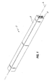
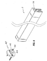
- a draft stopper device is shown according to the invention, denoted in its entirety by the reference number 1, which may be mounted on the bottom edge of a fixture of the type consisting of a hinged or sliding door or window.
- the device 1 essentially comprises a fixed, elongated, profile 2 with a cross-section substantially in the form of an overturned U and with a longitudinal axis L, which can be secured to the bottom edge B of the door P and inside which a movable profile 3 is slidably inserted, with the possibility of a limited transverse movement with respect to the fixed profile 2.
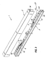
- the movable profile 3 is operatively coupled to the fixed profile 2 by means of suitable fastening means - denoted overall by 4 and 5 - which are able to limit the abovementioned relative transverse movement.
- the fastening means 4, 5 may consist of pair of arms 6, 7, each having one end 8, 9 hinged with the movable profile 3 and the other end 10, 11 joined to the fixed profile 2.
- the arms 6, 7 are slightly inclined with respect to the longitudinal direction of said profiles at angles of inclination ⁇ , ⁇ which are substantially equal and opposite.
- the ends 10, 11 of the arms 6, 7 are joined to the fixed profile 2 by means of respective rotatable supports 12, 13 which have an elongated shape and consist of profiled portions with a suitable cross-section, which can be inserted into a counter-shaped longitudinal seat 14 of the fixed profile 2.
- Elastic opposing means are provided for moving the movable profile 3 towards the fixed profile 2 when the door P is in the open position.
- these opposition means may consist of a pair of extension springs 15, 16 having a first end 17, 18 fixed to each of the arms 6, 7 and the other end 19, 20 fastened to a respective rotatable support 12, 13.
- Automatic actuating means denoted overall by the reference number 21, are also envisaged, said means being able to operate the movable profile 3 so as to move it transversely away from the fixed profile 2 and bring it into contact with the floor T when the door P is in the closed position.
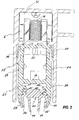
- the movable profile 3 is made entirely of plastic material and has a box-shaped portion 22 with a closed cross-section so as to increase its flexural and torsional rigidity.
- the closed cross-section comprises a pair of side walls 23, 24 which are joined together by transverse walls 25, 26.
- the transverse wall 26 is situated at a predetermined distance from the free end of the side walls so as to define a pair of longitudinal extensions 27, 28.
- the longitudinal extension 27, 28 have along their free longitudinal edges projecting flanges 29, 30 which may be coextruded with the longitudinal extensions 27, 28 and are designed to come into contact with the floor T when the door is in the closed position so as to define an effective fluid and sound barrier.
- the projecting flanges 29, 30 are made of a material different from that used for the remaining portions of the movable profile 3. More particularly, the base material of the projecting flanges 29, 20 is resiliently yielding so as to adapt to the irregularities of the floor T, while the base material of the remaining portions of the movable profile 3 is relatively rigid.
- the internal surface of the longitudinal extensions 27, 28 has one or more longitudinal projections 31, 31', 32, 32' directed transversely inwards for transversely retaining a removable seal 33 made of flexible material and if necessary also provided with vertical flanges 34, 34', 35, 35' defining acoustic and fluid seals.
- the movable profile 3 may have a pair of longitudinal lips 36, 37 which extend outwards from the side walls 23, 24 and are resiliently yielding so as to interact with the internal side wall of the fixed profile 3 and reduce the lateral play with the latter.
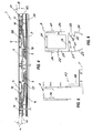
- the actuating means 21 comprise a plunger 38 which may at least partially slide in a direction substantially parallel to the profiles 2, 3 so as to bring the movable profile 3 from a rest position completely retracted inside the fixed profile 2, into an operative position completely extended from the fixed profile 2.
- the plunger 38 is at least partly housed inside the fixed profile 2 so as to be adaptable to doors of the sliding type.
- the actuating means may comprise a lever element 39 with an end 40 hinged at one end to the fixed profile 2 and having a free end 41 interacting on one side with the plunger 38 and on the other side with the jamb of the door S or with the opposite edge of another sliding door situated opposite.
- the lever element 39 may have a through-hole, not shown in the drawings, for screw-type adjustment of the plunger 38.
- an abutment element 42 is envisaged, said element being formed so as to interact with an adjustable end 43 of the plunger 38, when the sliding door is in the closed position.
- This abutment element may be secured onto the jamb S of the door P using suitable fixing means, such as, for example, one or more screws.
- the abutment element 42 comprises a pair of resiliently yielding lateral lugs 44, 45 able to engage with the fixed profile 2 so as to keep the door in the closed position.
- the width between the lateral lugs 44, 45 may be adjusted by means of a screw 46.
- the guide 47 which is able to guide the fixed profile in a longitudinal direction when the door is of the sliding type.
- the guide may consist of a fixed support 48 which can be secured to the floor T in the vicinity of the outgoing edge of the door P.
- the draft stopper device 1 according to the invention may be manufactured using a method comprising the steps described below.
- a first fixed, elongated, profile 2 with a predetermined longitudinal extension E' is prepared.
- a second step b) the second movable profile 3 with a length E" greater than or equal to the longitudinal extension E' of the fixed profile 2 is prepared.
- a third step c) the fastening means 4, 5 for performing connection to the fixed profile 2 are mounted on the movable profile 3 together with also the automatic actuating means 21 and the elastic opposing means able to move the movable profile 3 away from and towards the fixed profile 2.
- a fourth step d) the movable profile 3 is inserted inside the fixed profile 2.
- insertion may be performed by means of longitudinal sliding.
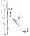
- a last step e) cutting of the movable profile 3 is performed, as shown in FIG. 11 and FIG. 12.
- the length E" of the movable profile 3 is adapted so that it is substantially equal to the longitudinal extension E' of the fixed profile 2, by means of a simple and quick procedure.
- the device according to the invention achieves the predefined objects and particular attention is drawn to its effectiveness as a low-cost sound barrier which is extremely light and easy to install.
- the device 1 according to the invention may be subject to numerous modifications and variants all falling within the inventive idea expressed in the accompanying claims. All the details may be replaced by other technically equivalent elements and the materials may differ according to requirements, without departing from the scope of the invention.
Landscapes
- Engineering & Computer Science (AREA)
- Civil Engineering (AREA)
- Structural Engineering (AREA)
- Specific Sealing Or Ventilating Devices For Doors And Windows (AREA)
- Wing Frames And Configurations (AREA)
Applications Claiming Priority (2)
| Application Number | Priority Date | Filing Date | Title |
|---|---|---|---|
| ITVI20020051 | 2002-03-20 | ||
| ITVI20020051 ITVI20020051A1 (it) | 2002-03-20 | 2002-03-20 | Dispositivo paraspifferi particolarmente per porte incernierate o scorrevoli ed altri infissi similari |
Publications (2)
| Publication Number | Publication Date |
|---|---|
| EP1347146A2 true EP1347146A2 (de) | 2003-09-24 |
| EP1347146A3 EP1347146A3 (de) | 2003-11-19 |
Family
ID=27773211
Family Applications (1)
| Application Number | Title | Priority Date | Filing Date |
|---|---|---|---|
| EP03006309A Withdrawn EP1347146A3 (de) | 2002-03-20 | 2003-03-20 | Zugluftstopper, insbesondere für schwenkbare oder Schiebetüren, sowie Verfahren zum Herstellen |
Country Status (2)
| Country | Link |
|---|---|
| EP (1) | EP1347146A3 (de) |
| IT (1) | ITVI20020051A1 (de) |
Cited By (4)
| Publication number | Priority date | Publication date | Assignee | Title |
|---|---|---|---|---|
| EP1717404A2 (de) * | 2005-04-26 | 2006-11-02 | Luigi Geron | Dichtungsstreifen insbesondere für Türen und Fenstern |
| DE202011001104U1 (de) * | 2011-01-07 | 2012-04-26 | Athmer Ohg | Dichtungsvorrichtung mit einem Dichtungsprofil und einem Mechanismus zum Verschieben des Dichtungsprofils bei Betätigung des Mechanismus |
| CH704410A1 (de) * | 2011-01-31 | 2012-07-31 | Planet Gdz Ag | Absenkdichtungsvorrichtung. |
| EP3757007A1 (de) * | 2019-06-25 | 2020-12-30 | The Boeing Company | Systeme und verfahren zur abdichtung eines kühlmöbels eines flugzeugs |
Citations (3)
| Publication number | Priority date | Publication date | Assignee | Title |
|---|---|---|---|---|
| EP0915226A2 (de) | 1997-11-05 | 1999-05-12 | Luigi Geron | Selbsteinstellender Zug Stopper für Tür- und Fensterrahmen oder dergleichen |
| EP0916802A2 (de) | 1997-11-11 | 1999-05-19 | Luigi Geron | Selbsttätig sich einstellender Betätigungsdruckknopf für einen automatischen Zugluftstopper und mit dem Druckknopf ausgestatteter Zugluftstopper |
| EP0940551A1 (de) | 1998-03-06 | 1999-09-08 | Truce B.V. | Dichtungsprofil für Türen |
Family Cites Families (4)
| Publication number | Priority date | Publication date | Assignee | Title |
|---|---|---|---|---|
| JP3328525B2 (ja) * | 1996-11-19 | 2002-09-24 | 日本板硝子環境アメニティ株式会社 | 電磁波シールドドア構造 |
| JPH10238251A (ja) * | 1997-03-03 | 1998-09-08 | Shibutani:Kk | ドアボトムの密封装置 |
| DE29720854U1 (de) * | 1997-11-25 | 1999-04-01 | Kross Manfred | Automatische Tür-Bodendichtung |
| ATE392530T1 (de) * | 2001-07-24 | 2008-05-15 | Planet Gdz Ag | Absenkbare türdichtung |
-
2002
- 2002-03-20 IT ITVI20020051 patent/ITVI20020051A1/it unknown
-
2003
- 2003-03-20 EP EP03006309A patent/EP1347146A3/de not_active Withdrawn
Patent Citations (3)
| Publication number | Priority date | Publication date | Assignee | Title |
|---|---|---|---|---|
| EP0915226A2 (de) | 1997-11-05 | 1999-05-12 | Luigi Geron | Selbsteinstellender Zug Stopper für Tür- und Fensterrahmen oder dergleichen |
| EP0916802A2 (de) | 1997-11-11 | 1999-05-19 | Luigi Geron | Selbsttätig sich einstellender Betätigungsdruckknopf für einen automatischen Zugluftstopper und mit dem Druckknopf ausgestatteter Zugluftstopper |
| EP0940551A1 (de) | 1998-03-06 | 1999-09-08 | Truce B.V. | Dichtungsprofil für Türen |
Cited By (7)
| Publication number | Priority date | Publication date | Assignee | Title |
|---|---|---|---|---|
| EP1717404A2 (de) * | 2005-04-26 | 2006-11-02 | Luigi Geron | Dichtungsstreifen insbesondere für Türen und Fenstern |
| EP1717404A3 (de) * | 2005-04-26 | 2011-12-28 | Luigi Geron | Dichtungsstreifen insbesondere für Türen und Fenstern |
| DE202011001104U1 (de) * | 2011-01-07 | 2012-04-26 | Athmer Ohg | Dichtungsvorrichtung mit einem Dichtungsprofil und einem Mechanismus zum Verschieben des Dichtungsprofils bei Betätigung des Mechanismus |
| EP2474698A3 (de) * | 2011-01-07 | 2014-11-05 | Athmer oHG | Dichtungsvorrichtung mit einem Dichtungsprofil und einem Mechanismus zum Verschieben des Dichtungsprofils bei Betätigung des Mechanismus |
| CH704410A1 (de) * | 2011-01-31 | 2012-07-31 | Planet Gdz Ag | Absenkdichtungsvorrichtung. |
| EP3757007A1 (de) * | 2019-06-25 | 2020-12-30 | The Boeing Company | Systeme und verfahren zur abdichtung eines kühlmöbels eines flugzeugs |
| US11525622B2 (en) | 2019-06-25 | 2022-12-13 | The Boeing Company | Systems and methods for sealing a refrigerated galley of an aircraft |
Also Published As
| Publication number | Publication date |
|---|---|
| ITVI20020051A1 (it) | 2003-09-22 |
| EP1347146A3 (de) | 2003-11-19 |
Similar Documents
| Publication | Publication Date | Title |
|---|---|---|
| CA2928089C (en) | Entryway with articulating threshold | |
| EP3147445B1 (de) | Tür oder fenster | |
| DK2949855T3 (en) | Door seal, door with door seal and method of manufacture thereof | |
| CA2341997A1 (en) | A spring mounting arrangement for a sash window counterbalance arrangement | |
| JP2015531036A (ja) | 2つのシール面を有するドアシール | |
| US6041550A (en) | Resilient cover for covering a spring of a jamb liner and for attenuating noise generated by spring movement | |
| AU2017267190B2 (en) | Threshold seal apparatus, a kit of parts and a method | |
| EP1347146A2 (de) | Zugluftstopper, insbesondere für schwenkbare oder Schiebetüren, sowie Verfahren zum Herstellen | |
| JPH0370077B2 (de) | ||
| KR101472225B1 (ko) | 창호용 방풍부재, 이를 가지는 창호 프레임 및 방풍부재의 시공방법 | |
| EP2246515A1 (de) | Befestigungsanordnung eines Türdichtungssystems | |
| KR20180002322U (ko) | 창호용 가스켓 | |
| GB2220220A (en) | Door sealing means | |
| US2554862A (en) | Sash mounting | |
| KR101886121B1 (ko) | 스크린 가이드장치 및 이를 포함하는 블라인드 | |
| EP1579098B1 (de) | Zugluftstoppervorrichtung, insbesondere für türen und dergleichen | |
| GB2060040A (en) | An improved draught excluder | |
| KR102304996B1 (ko) | 미닫이창용 여밈장치 | |
| JPH07317459A (ja) | 扉の隙間用シャッター装置 | |
| US5784840A (en) | Adjustable window construction | |
| AU2016262687A1 (en) | Improved sliding door soft close system | |
| KR200409238Y1 (ko) | 강화유리도어프레임의 소음방지구조 | |
| AU2003200433B2 (en) | A fingerguard | |
| KR200305314Y1 (ko) | 밀봉유니트 | |
| US5921059A (en) | Door fit for a hollow core panel door |
Legal Events
| Date | Code | Title | Description |
|---|---|---|---|
| PUAI | Public reference made under article 153(3) epc to a published international application that has entered the european phase |
Free format text: ORIGINAL CODE: 0009012 |
|
| AK | Designated contracting states |
Kind code of ref document: A2 Designated state(s): AT BE BG CH CY CZ DE DK EE ES FI FR GB GR HU IE IT LI LU MC NL PT SE SI SK TR |
|
| AX | Request for extension of the european patent |
Extension state: AL LT LV MK RO |
|
| PUAL | Search report despatched |
Free format text: ORIGINAL CODE: 0009013 |
|
| AK | Designated contracting states |
Kind code of ref document: A3 Designated state(s): AT BE BG CH CY CZ DE DK EE ES FI FR GB GR HU IE IT LI LU MC NL PT SE SI SK TR |
|
| AX | Request for extension of the european patent |
Extension state: AL LT LV MK RO |
|
| 17P | Request for examination filed |
Effective date: 20040519 |
|
| AKX | Designation fees paid |
Designated state(s): AT BE BG CH CY CZ DE DK EE ES FI FR GB GR HU IE IT LI LU MC NL PT SE SI SK TR |
|
| STAA | Information on the status of an ep patent application or granted ep patent |
Free format text: STATUS: THE APPLICATION IS DEEMED TO BE WITHDRAWN |
|
| 18D | Application deemed to be withdrawn |
Effective date: 20060301 |