EP1346897A1 - Primärfederung für Schienenfahrzeuge und Verfahren zur Verstellung - Google Patents
Primärfederung für Schienenfahrzeuge und Verfahren zur Verstellung Download PDFInfo
- Publication number
- EP1346897A1 EP1346897A1 EP03005977A EP03005977A EP1346897A1 EP 1346897 A1 EP1346897 A1 EP 1346897A1 EP 03005977 A EP03005977 A EP 03005977A EP 03005977 A EP03005977 A EP 03005977A EP 1346897 A1 EP1346897 A1 EP 1346897A1
- Authority
- EP
- European Patent Office
- Prior art keywords
- boxes
- blocks
- suspension
- bogie
- box
- Prior art date
- Legal status (The legal status is an assumption and is not a legal conclusion. Google has not performed a legal analysis and makes no representation as to the accuracy of the status listed.)
- Withdrawn
Links
- 239000000725 suspension Substances 0.000 title claims abstract description 45
- 238000000034 method Methods 0.000 title claims abstract description 10
- 239000013013 elastic material Substances 0.000 claims abstract description 23
- 230000010355 oscillation Effects 0.000 abstract description 7
- 230000006835 compression Effects 0.000 description 4
- 238000007906 compression Methods 0.000 description 4
- 239000000463 material Substances 0.000 description 3
- 229910052751 metal Inorganic materials 0.000 description 3
- 239000002184 metal Substances 0.000 description 2
- 230000008878 coupling Effects 0.000 description 1
- 238000010168 coupling process Methods 0.000 description 1
- 238000005859 coupling reaction Methods 0.000 description 1
- 239000007769 metal material Substances 0.000 description 1
- 210000000056 organ Anatomy 0.000 description 1
- 230000000750 progressive effect Effects 0.000 description 1
- 238000003466 welding Methods 0.000 description 1
Images
Classifications
-
- B—PERFORMING OPERATIONS; TRANSPORTING
- B61—RAILWAYS
- B61F—RAIL VEHICLE SUSPENSIONS, e.g. UNDERFRAMES, BOGIES OR ARRANGEMENTS OF WHEEL AXLES; RAIL VEHICLES FOR USE ON TRACKS OF DIFFERENT WIDTH; PREVENTING DERAILING OF RAIL VEHICLES; WHEEL GUARDS, OBSTRUCTION REMOVERS OR THE LIKE FOR RAIL VEHICLES
- B61F5/00—Constructional details of bogies; Connections between bogies and vehicle underframes; Arrangements or devices for adjusting or allowing self-adjustment of wheel axles or bogies when rounding curves
- B61F5/26—Mounting or securing axle-boxes in vehicle or bogie underframes
- B61F5/30—Axle-boxes mounted for movement under spring control in vehicle or bogie underframes
- B61F5/305—Axle-boxes mounted for movement under spring control in vehicle or bogie underframes incorporating rubber springs
Definitions
- the present invention relates to a primary suspension for railway vehicles, in particular a primary suspension device whose position in relation to the bogie can be adjusted without complete dismantling.
- axle sleeve is connected, at its sides, by said blocks of elastic material to supports joined to the bogie frame, called brackets.
- the suspensions positioned between wheel arrangement and bogie frame are commonly called “primary suspensions”, whereas the term “secondary suspensions” refers to those positioned between the bogie frame and the frame of the railway vehicle.
- the blocks of elastic material are placed in such an inclined position that the load of the vehicle causes a certain compression thereon.
- This adjustment entails the dismantling of the wheel arrangement from the bogie, in order to permit the replacement of the blocks of elastic material with others of different dimensions, or the introduction of special shims, thus adjusting the position of the bogie frame over the track plane and/or the distribution of the loads on the vehicle's various primary suspensions.
- said boxes can be connected to said brackets by screws and present elongated slots through which said screws pass.
- the device comprises a fixing plate for each box, said plate having a number of threaded holes and being destined to tighten said box against the bracket, by said screws.
- the invention also relates to a method of adjusting a primary suspension such as described above, connected to one or more brackets integral with the bogie frame of a railway vehicle, comprising:
- the method comprises the introduction of an element (known as a shim) in contact with the box, above it and in contact with the bracket in a position that makes it possible to fix the box (and therefore the suspension) in the new position.
- an element known as a shim
- the weight of the vehicle, combined with the oscillations, would cause the box to slip with respect to the bracket, since the box has elongated slots and not circular holes where the screws pass, in order to allow it to be moved during the adjustment step.
- the bracket presents a special protuberance above the position occupied by the central part of the box.
- the method according to the present invention is suitably performed after the suspension has been unloaded, for example by suitably raising the vehicle with respect to the track plane with suitable means.
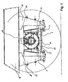
- Figure 1 shows a primary suspension fixed to the frame 14 of the bogie, with a bogie axle mounted thereon. It is possible to distinguish the axle sleeve 1 receiving the end of the bogie axle, said axle sleeve being closed at the front with a cover 15 by means of a set of screws.
- An oscillation viscous dampening system 24 is generally present, represented only partially in the drawing, which works in parallel to the primary suspension and can, for example, connect the cover 15 to the frame 14 of the bogie.
- the axle sleeve 1 with the blocks of elastic material 3 and 3' (there are two more, hidden in figure 1) and the boxes 9 and 9', is part of a primary suspension that is housed between two structures, commonly said brackets, 10 and 10' fixed (for example by welding) to the frame 14 of the bogie; the boxes 9 and 9' are connected by bolts to brackets 10 and 10'.
- the distance between brackets 10 and 10' is generally such that inserting the primary suspension as shown in figure 1 it is necessary to give a certain pre-compression to the blocks of elastic material.
- a structure 16 connects the two brackets in the lower part thus giving suitable rigidity to the system and constituting an end of stroke element for the axle sleeve 1, should its oscillations around its prefixed position, due to shakes that occur during motion (with the deformation of the blocks of elastic material) exceed a certain limit.
- Suitable end of stroke elements can also be advantageously provided above the axle sleeve.
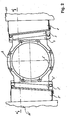
- axle sleeve 1 whose cavity 1' is destined to house the end of the bogie axle with the suitable antifriction organs, in order to permit the relative rotation of the parts.
- the axle sleeve 1 presents at its sides two bodies 2 and 2' to which the blocks of elastic material 3, 3', 4 and 4' are fixed. The latter are fixed to the wings 7, 7', 8, and 8' of the boxes 9 and 9'.
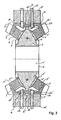
- the blocks of elastic material 3, 3', 4 and 4' present, on two opposite faces, metal plates and wedge-shaped elements 5, 5', 6 and 6', which present elements for fixing the plates to boxes 9 and 9' and the wedge-shaped elements 5, 5', 6 and 6' to the bodies 2 and 2' of the axle sleeve 1.
- the plates and the wedge-shaped elements are integral with the elastic material of the blocks.
- Said material can be advantageously rubber, which is cured with said wedge-shaped elements and the plates already positioned, in such a way as to form a single structure.
- blocks 3, 3', 4 and 4' are in an inclined position in relation to the vertical direction, so that the weight of the vehicle, which is transmitted through boxes 9 and 9', causes a certain compression of the blocks.
- they, also subject to shear stress, must never be subject to traction, as is well known.
- the inclined position of the blocks is particularly advantageous in those cases, such as that of the suspension shown in the figures, in which there is no further elastic suspension system, such as a system of suspension springs, working in parallel with respect to the blocks.
- plates 12 and 12' can be provided, which constitute the fixing element for the boxes 9 and 9' against the brackets.
- the screws 11 pass through the boxes 9 and 9' in slots made thereon and are screwed into threaded holes of the plates 12 and 12'.
- the bodies 2 and 2' of the axle sleeve 1 can present ends 25 and 25' of various shapes. They can constitute an end of stroke element for the axle sleeve 1 in the longitudinal movements caused by the oscillations that occur during motion, thus touching, due to the oscillations that exceed a certain extent, the plates 12 and 12'.
- the boxes 9 and 9' present elongated slots 17 through which the screws 11 can pass.
- Their elongated shape makes it possible to position the boxes in different positions along the vertical axis.
- the screws 11 can be screwed into the threaded holes 18 in plates 12 and 12'; advantageously, the protuberances 19, coaxial with the holes 18 may be present, which are destined to be lodged in special cavities 30 made in the box 9 in correspondence with the slots 17, as shown in figure 3.
- This coupling enables easier assembly and is also useful during the position adjustment of the suspension in relation to the frame 14 of the bogie, which can be performed simply by loosening the screws 11 and shifting the suspension vertically. This operation is generally performed after having lifted the vehicle sufficiently to unload the weight that usually weighs on the suspension, in order to permit adjustment.
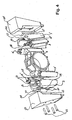
- the operation can suitably be completed by the introduction of shims, indicated with 22 in figure 4, preferably of a rigid material such as a metal material above the boxes and below the protuberances 21 of the brackets, as shown in figure 1, protuberances that are specifically provided above the position in which the central upper part of the box is located, preferably above the housing of the keys 13 and 13'; preferably each box will have one housing (23 in figure 4) for receiving said shim; this allows to maintain the suspension in position even when the vehicle is loaded on the suspensions again.
- the tightening of the screws completes the adjustment operation.
- the housing 23 is preferably positioned in the upper part of the box.
- the shims 22 may have any suitable shape, and can be simple parallelepipeds with a rectangular section with a suitable height. As said, they can be inserted above boxes 9 and 9'. Instead of between the boxes and the brackets, or the protuberances 21 thereof, they may also be inserted between the boxes and the frame 14 of the bogie or between the protuberances integral with the latter and the boxes.
Landscapes
- Engineering & Computer Science (AREA)
- Mechanical Engineering (AREA)
- Springs (AREA)
- Vibration Prevention Devices (AREA)
Applications Claiming Priority (2)
| Application Number | Priority Date | Filing Date | Title |
|---|---|---|---|
| ITMI20020577 | 2002-03-19 | ||
| IT2002MI000577A ITMI20020577A1 (it) | 2002-03-19 | 2002-03-19 | Sospensione primaria per veicoli ferroviari e simili e metodo di regolazione della stessa |
Publications (1)
| Publication Number | Publication Date |
|---|---|
| EP1346897A1 true EP1346897A1 (de) | 2003-09-24 |
Family
ID=11449537
Family Applications (1)
| Application Number | Title | Priority Date | Filing Date |
|---|---|---|---|
| EP03005977A Withdrawn EP1346897A1 (de) | 2002-03-19 | 2003-03-18 | Primärfederung für Schienenfahrzeuge und Verfahren zur Verstellung |
Country Status (2)
| Country | Link |
|---|---|
| EP (1) | EP1346897A1 (de) |
| IT (1) | ITMI20020577A1 (de) |
Families Citing this family (1)
| Publication number | Priority date | Publication date | Assignee | Title |
|---|---|---|---|---|
| CN110001700B (zh) * | 2019-04-19 | 2023-11-28 | 中车洛阳机车有限公司 | 一种两轴工程车转序用轮轴装置 |
Citations (7)
| Publication number | Priority date | Publication date | Assignee | Title |
|---|---|---|---|---|
| DE882414C (de) * | 1950-04-26 | 1953-07-09 | Metallgummi G M B H | Abfederung fuer Fahrzeuge, insbesondere fuer Schienenfahrzeuge |
| DE942932C (de) * | 1952-11-18 | 1956-05-09 | Metallgummi G M B H | Abfederung fuer Schienenfahrzeuge |
| US2802662A (en) * | 1952-09-03 | 1957-08-13 | Metalastik Ltd | Resilient mounting for rail and like vehicles |
| DE1127938B (de) * | 1956-05-29 | 1962-04-19 | Deutsche Bundesbahn | Lastabhaengig regelbare Gummifeder fuer Fahrzeuge, insbesondere Schienenfahrzeuge |
| AT267592B (de) * | 1965-08-04 | 1969-01-10 | Waggonfabrik Jos Rathgeber A G | Drehgestell für Schienenfahrzeuge |
| DE3026528A1 (de) * | 1980-07-12 | 1982-02-11 | M.A.N. Maschinenfabrik Augsburg-Nürnberg AG, 8500 Nürnberg | Hoeheneinstellbares achslager fuer schienenfahrzeuge |
| US6053112A (en) * | 1998-12-07 | 2000-04-25 | Buckeye Steel Castings Company | Shimming of railway car primary suspensions |
-
2002
- 2002-03-19 IT IT2002MI000577A patent/ITMI20020577A1/it unknown
-
2003
- 2003-03-18 EP EP03005977A patent/EP1346897A1/de not_active Withdrawn
Patent Citations (7)
| Publication number | Priority date | Publication date | Assignee | Title |
|---|---|---|---|---|
| DE882414C (de) * | 1950-04-26 | 1953-07-09 | Metallgummi G M B H | Abfederung fuer Fahrzeuge, insbesondere fuer Schienenfahrzeuge |
| US2802662A (en) * | 1952-09-03 | 1957-08-13 | Metalastik Ltd | Resilient mounting for rail and like vehicles |
| DE942932C (de) * | 1952-11-18 | 1956-05-09 | Metallgummi G M B H | Abfederung fuer Schienenfahrzeuge |
| DE1127938B (de) * | 1956-05-29 | 1962-04-19 | Deutsche Bundesbahn | Lastabhaengig regelbare Gummifeder fuer Fahrzeuge, insbesondere Schienenfahrzeuge |
| AT267592B (de) * | 1965-08-04 | 1969-01-10 | Waggonfabrik Jos Rathgeber A G | Drehgestell für Schienenfahrzeuge |
| DE3026528A1 (de) * | 1980-07-12 | 1982-02-11 | M.A.N. Maschinenfabrik Augsburg-Nürnberg AG, 8500 Nürnberg | Hoeheneinstellbares achslager fuer schienenfahrzeuge |
| US6053112A (en) * | 1998-12-07 | 2000-04-25 | Buckeye Steel Castings Company | Shimming of railway car primary suspensions |
Also Published As
| Publication number | Publication date |
|---|---|
| ITMI20020577A0 (it) | 2002-03-19 |
| ITMI20020577A1 (it) | 2003-09-19 |
Similar Documents
| Publication | Publication Date | Title |
|---|---|---|
| AU716460B2 (en) | Means for and method of mounting a suspension member to an axle housing | |
| CN112298241B (zh) | 转向架及轨道车辆 | |
| EP1901931B1 (de) | Gummifeder für fahrzeugradachsaufhängung | |
| EP4008601A1 (de) | Drehgestell und schienenfahrzeug | |
| MX2007008692A (es) | Cojinete lateral para vagon de mercancias de ferrocarril. | |
| US7328660B2 (en) | Flexible connection device between a bogey side beam and an axle-box | |
| GB701623A (en) | Improvements in spring suspension for vehicles | |
| US6220580B1 (en) | Leaf spring pivot bearing and assembly with adjustment pilot | |
| US5611284A (en) | Rail truck suspension and journal housing retention assembly | |
| KR20060028752A (ko) | 철도차량용 액슬박스 지지장치 | |
| USRE22558E (en) | Railroad cab truck | |
| EP0501221A1 (de) | Aufhängung | |
| EP1346897A1 (de) | Primärfederung für Schienenfahrzeuge und Verfahren zur Verstellung | |
| US5716162A (en) | Dual-stage mounting system for vibratory compactor drum | |
| RU2120873C1 (ru) | Способ повышения динамических характеристик рельсового транспортного средства (варианты). способ повышения надежности работающих на сжатие эластичных упругих и упруго-демпфирующих элементов. поводковое устройство. люлечное подвешивание рельсового транспортного средства. устройство для предварительной поперечной установки надрессорной балки. амортизирующий блок (варианты) | |
| US2637569A (en) | Tandem suspension for tractors and trailers | |
| KR101315228B1 (ko) | 하중에 따른 철도차량 대차의 코니컬스프링 변위량과 축상고 측정방법 및 그 장치 | |
| US2814501A (en) | Vehicle tandem axle suspension | |
| CN112644547B (zh) | 一种轨道车辆及其转向架 | |
| CN108839663A (zh) | 一种工艺转向架驱动结构以及工艺转向架 | |
| CN209258141U (zh) | 一种构架以及工艺转向架 | |
| CN209022924U (zh) | 一种动力工艺转向架 | |
| US12459320B2 (en) | Vehicle suspension adaptor assemblies and methods | |
| CN215793045U (zh) | 一种加强型半挂车悬架结构 | |
| US6220177B1 (en) | Bogie for railway vehicle and process for manufacturing same |
Legal Events
| Date | Code | Title | Description |
|---|---|---|---|
| PUAI | Public reference made under article 153(3) epc to a published international application that has entered the european phase |
Free format text: ORIGINAL CODE: 0009012 |
|
| AK | Designated contracting states |
Kind code of ref document: A1 Designated state(s): AT BE BG CH CY CZ DE DK EE ES FI FR GB GR HU IE IT LI LU MC NL PT RO SE SI SK TR |
|
| AX | Request for extension of the european patent |
Extension state: AL LT LV MK |
|
| AKX | Designation fees paid | ||
| REG | Reference to a national code |
Ref country code: DE Ref legal event code: 8566 |
|
| STAA | Information on the status of an ep patent application or granted ep patent |
Free format text: STATUS: THE APPLICATION IS DEEMED TO BE WITHDRAWN |
|
| 18D | Application deemed to be withdrawn |
Effective date: 20040325 |