EP1344996A1 - Dispositif et procédé pour le refroidissement de la neige - Google Patents
Dispositif et procédé pour le refroidissement de la neige Download PDFInfo
- Publication number
- EP1344996A1 EP1344996A1 EP02405190A EP02405190A EP1344996A1 EP 1344996 A1 EP1344996 A1 EP 1344996A1 EP 02405190 A EP02405190 A EP 02405190A EP 02405190 A EP02405190 A EP 02405190A EP 1344996 A1 EP1344996 A1 EP 1344996A1
- Authority
- EP
- European Patent Office
- Prior art keywords
- coolant
- heat
- cooling
- cooling mat
- snow
- Prior art date
- Legal status (The legal status is an assumption and is not a legal conclusion. Google has not performed a legal analysis and makes no representation as to the accuracy of the status listed.)
- Withdrawn
Links
Images

Classifications
-
- F—MECHANICAL ENGINEERING; LIGHTING; HEATING; WEAPONS; BLASTING
- F25—REFRIGERATION OR COOLING; COMBINED HEATING AND REFRIGERATION SYSTEMS; HEAT PUMP SYSTEMS; MANUFACTURE OR STORAGE OF ICE; LIQUEFACTION SOLIDIFICATION OF GASES
- F25C—PRODUCING, WORKING OR HANDLING ICE
- F25C3/00—Processes or apparatus specially adapted for producing ice or snow for winter sports or similar recreational purposes, e.g. for sporting installations; Producing artificial snow
- F25C3/04—Processes or apparatus specially adapted for producing ice or snow for winter sports or similar recreational purposes, e.g. for sporting installations; Producing artificial snow for sledging or ski trails; Producing artificial snow
-
- E—FIXED CONSTRUCTIONS
- E01—CONSTRUCTION OF ROADS, RAILWAYS, OR BRIDGES
- E01C—CONSTRUCTION OF, OR SURFACES FOR, ROADS, SPORTS GROUNDS, OR THE LIKE; MACHINES OR AUXILIARY TOOLS FOR CONSTRUCTION OR REPAIR
- E01C13/00—Pavings or foundations specially adapted for playgrounds or sports grounds; Drainage, irrigation or heating of sports grounds
- E01C13/10—Pavings or foundations specially adapted for playgrounds or sports grounds; Drainage, irrigation or heating of sports grounds for artificial surfaces for outdoor or indoor practice of snow or ice sports
- E01C13/12—Pavings or foundations specially adapted for playgrounds or sports grounds; Drainage, irrigation or heating of sports grounds for artificial surfaces for outdoor or indoor practice of snow or ice sports for snow sports, e.g. skiing or ski tow track
-
- F—MECHANICAL ENGINEERING; LIGHTING; HEATING; WEAPONS; BLASTING
- F25—REFRIGERATION OR COOLING; COMBINED HEATING AND REFRIGERATION SYSTEMS; HEAT PUMP SYSTEMS; MANUFACTURE OR STORAGE OF ICE; LIQUEFACTION SOLIDIFICATION OF GASES
- F25B—REFRIGERATION MACHINES, PLANTS OR SYSTEMS; COMBINED HEATING AND REFRIGERATION SYSTEMS; HEAT PUMP SYSTEMS
- F25B29/00—Combined heating and refrigeration systems, e.g. operating alternately or simultaneously
- F25B29/003—Combined heating and refrigeration systems, e.g. operating alternately or simultaneously of the compression type system
Definitions
- the invention relates to a method and an apparatus for cooling Snow according to the preamble of the independent claim of respective category.
- DE-A-198 43 901 describes a method and a device for Preservation of snow known.
- Such a device serves For example, critical points of ski runs, in particular stabilize those that are prepared with artificial snow in order to Get snow cover longer and better.
- Such critical points could heavily used or narrow downhill area, south-facing slopes, Descents. Slope end areas in front of lifts or boarding areas from Lifts.
- a device is proposed which includes a cooling mat system that is in predetermined areas - that is z. B. at the critical points mentioned.
- the cooling mat system is flowed through by a coolant.
- the Artificial snow, natural snow or the base in the specified Areas cooled down, so that thawing the snow pad efficiently can be counteracted.
- the snow or the Snow cover especially possible at critical points of descents.
- the underground is protected.
- Such methods are not limited to use in ski slopes, but can also be found on ski jumps, half pipes and Parking spaces are used.
- a method for cooling snow in one is predeterminable range proposed, in which an at least one Comprehensive cooling mat system is designed in the area, a coolant is introduced into the cooling mat system via a feed the coolant via a return from the cooling mat system is dissipated, and the coolant with a unit that with the Supply and return can be connected, heat is extracted, which unit as a heat pump with a cold side and a warm side is operated, heat being removed from the coolant on the cold side, and on the warm side energy in the form of useful heat to one Consumer or a heat reservoir is delivered.
- a suitable device for cooling Snow proposed in a predeterminable area with at least one a cooling mat system to be laid out in the Area with a supply for introducing a coolant into the Cooling mat system, with a return for removing the coolant the cooling mat system, as well as with a unit for extracting Heat from the coolant, which unit with the supply and the Recirculation is connectable, and as a heat pump with a cold side and a warm side is configured, with an evaporator on the cold side Extracting heat from the coolant is provided, and on the On the hot side, a condenser is provided for energy delivery, the agent includes with which the energy as useful heat a consumer or can be fed to a heat reservoir.
- the invention is therefore based on the idea of snow as a heat sink To use heat pump.
- the heat pump in Advantageously two functions: On the one hand by the Coolant flow through the cooling mat system to the snow or Extracted heat from the ground to preserve the snow, that is Snow is being cooled.
- the heat pump on the Warm side energy used as useful heat With this A swimming pool, for example, can be used for useful heat
- a building's heating system can be supported, which can provide useful heat be used for hot water production or for industrial purposes.
- the method according to the invention and the Device according to the invention is particularly efficient, especially with regard to energy use. This results in very economical operation.
- the use of cooling and heating output falls at the same time Point in time, that is, the cold is needed at the same time or provided like the heat.
- the unit preferably gives the heat to one on the warm side liquid heat transfer medium, especially water, because this creates a particularly simple use for heating purposes is made possible.
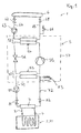
- Fig. 1 illustrates a block diagram of an embodiment of the Invention.
- An apparatus for cooling snow is shown, the is generally designated by the reference number 1.
- the device 1 comprises a cooling mat system 2, which here has only one cooling mat 21, and a unit 5, which acts as a heat pump with a cold side 51 and a Warm side 52 is designed.
- the cold side 51 of the heat pump 5 cools a coolant, which in one Cooling circuit is circulated through the cooling mat 21.
- the cooling circuit includes a flow line 71 in which a coolant pump 91 is provided and which are explained in more detail later on via a shut-off valve 81 Distributor 7 for the coolant leads.
- the distributor 7 is via a feeder 3 and a return 4 connected to the cooling mat system 2.
- a return line 72 leads from the distributor 7 to another Shut-off valve 82 to the cold side 51 of the unit 5, so that the cooling circuit is closed.
- the coolant pump 91 conveys the preferably liquid coolant to the Distributor 7. From there it flows through feed 3 to the cooling mat system 2, which is laid out in the snow, cools the snow and flows through the Return 4 in the distributor 7 and from there back to the cold side 51 of the Unit 5, where heat is extracted from the coolant.
- the coolant is preferably an environmentally friendly liquid Alcohol-based.
- the warm side 52 of the heat pump heats a preferably liquid one Heat transfer medium that is circulated in a heat cycle.
- the Heat circuit comprises a connecting line 65, which via a valve 61 a consumer 6 or a heat reservoir 6 leads. From this leads a second connecting line 64 via a valve 62 to one Circulation pump 63 and from there back to the hot side 52 of the unit 5, so that the heat cycle is closed.
- a ventilation device 66 is also provided in the heat cycle.
- the heat transfer medium is preferably water.
- frost protection that is measures must be taken to prevent accidental freezing of the heat transfer medium, especially when it is at a standstill. This can the heat transfer medium contains an antifreeze in a manner known per se.
- the unit 5 is designed in a manner known per se as a heat pump and comprises on the cold side 51 an evaporator 53 of the coolant removes heat from the cooling circuit by evaporating a liquid.
- the steam is then compressed in a compressor 55 and then fed on the hot side to a condenser 54, in which the steam condenses and gives off heat to the heat transfer medium in the heat cycle.
- the Liquid is then expanded via an expansion valve 56 and again the Evaporator 53 supplied.
- Cooling mat system 2 designed in the snow in the area to be cooled and covered with snow.
- the cooling mat system 2 is preferably on one placed critical point of a ski run explained above.
- the coolant flows through the cooling mat system 2 and thus cools the surrounding Snow, for example down to minus seven degrees Celsius. Thereby the snowpack becomes much more stable and lasts longer because or defrosting is counteracted efficiently. Cooling the cooling mat 21 leads to a layer of hard snow and thus to a longer hold of the Snow.
- the coolant is then in the evaporator 53 on the cold side 51 Heat pump 5 extracted heat.
- Heat pump 5 On the warm side 52 of the heat pump 5, heat is supplied to the heat transfer medium of the heat cycle.
- the energy in the form of useful heat is sent to the consumer or supplied to the heat reservoir 6.
- the consumer 6 can for example, heating a swimming pool, e.g. B in a hotel, that is close to the ski slope.
- the consumer 6 can Be a water heater, a heater or support one other heating system.
- the useful heat dissipated from the heat pump 5 can be used in a variety of ways, including heating of event tents, stables, public buildings etc. Of course you can Useful heat can also be supplied to a heat store.
- the snow cooled by the cooling mat system 2 thus serves as Heat sink of the heat pump 5.
- the unit 5 is preferably arranged in a housing 57 which for is designed for mobile use outdoors, that is, the housing 57 weatherproof and protects the unit 5 against weather and environmental influences.
- the unit 5 can thus be placed anywhere in the terrain be, namely in the vicinity of those areas of a ski run, in where the snow should be cooled and thus made particularly durable.
- the cooling circuit can be an open, i.e. unpressurized system be designed. Then there is usually a reservoir for that Coolant is provided, from which the coolant pump 91 the coolant promotes and into which the coolant is recirculated. But it is also possible the cooling circuit as a closed, pressurized system embody. Then an expansion tank for the coolant be provided. Preferably, the reservoir or Expansion tank arranged in the housing 57 of the unit 5. At the Housing 57 can be provided with a fill level indicator for the coolant.
- 57 are provided on the housing in order to check the horizontal or vertical position of the housing 57, for example an integrated spirit level.
- the unit 5 in a simple manner to the desired location can be transported, for example by means of a Slope preparation device, are preferably on the housing 57, facilities provided, for example lifting eyes on which the unit 5 by means of Dozer blade can be raised.
- the housing 57 fasteners and / or guide means, for example rails or Grooves to be provided in order to secure the unit 5 on the loading area Mount slope grooming equipment.
- the housing 57 can also Have fasteners with which it is on the ground or off-road is fixable.
- Another advantageous measure is to have one in the unit 5 Provide heater 83 with which the coolant in the cooling circuit heat can be supplied. This can usually in the snow frozen cooling mat 21 to be heated before disassembly, so that it is melted freely.
- Collection means are preferably on or in the housing 57 a drip pan, provided to prevent uncontrolled leakage of Avoid coolant in the environment.
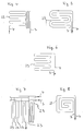
- FIG. 2 shows a top view of an exemplary embodiment of the cooling mat 21.
- Fig. 3 is such a cooling mat 21, inserted in the snow, in section shown.
- the cooling mat 21 comprises a fabric-like carrier material 22, preferably made of a weather-resistant plastic, the one network-like structure with a network width of typically a few, for example, has three to four centimeters.
- a line 23 is arranged, which the feed 3 with the Feedback 4 connects.
- the line 23 is from the coolant flows through. It is fixed to the carrier material 22 by means of fixations 24 attached.
- Plastic straps for example, can be used as fixings 24 be used.
- the line 23 is preferably a flexible pipe made of plastic material.
- the line 23 is in shape of several, arranged essentially parallel to one another Loops passed over the carrier material.
- this is only an example to understand.
- FIG. 4 shows an arrangement in which the Line 23 forms two groups of parallel loops, the Loops of the first group are perpendicular to those of the second group. 5, the line 23 initially runs in several loops and then back parallel to these loops in the opposite direction. In the 8, the line 23 initially runs in a spiral inside and then back outwards parallel to this spiral.
- Fig. 7 shows a variant with several, partially nested Lines 21 each of which on the one hand with the feed 3 and on the other is connected to the return 4. It goes without saying that too other arrangements of the line or lines 23 are possible.
- the cooling mat 21 Due to the described design of the cooling mat 21 with the fabric-like carrier material 22 and the flexible line 23 for the Coolant, the cooling mat 21 can be rolled up. That has the advantage of being is easier to transport and can be stowed away to save space.
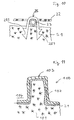
- the cooling mat 21 inserted between two layers of ice or snow S1, S2.
- the cooling mat 21 is arranged so that the carrier material 22 upwards comes to rest, so the line 23 between the floor and the Carrier material 22 lies.
- the ski slope is on layer S2. This The arrangement has the advantage that the carrier material 22 leads the lines 23 protects, for example against snowboard or ski edges.
- the lines 23 and in particular also the carrier material 22 visible, which is why preferably a bright color, e.g. B. red. Then she can Layer S2 can be rebuilt with artificial snow, for example.
- An advantageous measure, especially with regard to environmental protection is to provide a collection system 26 under the cooling mat 21, the comprises a material impermeable to the coolant, so that a uncontrolled leakage of the coolant into the environment is prevented.
- the cooling mat 21 can without further Fasteners or fasteners can be placed in the snow and freezes there when it cools, so that it also slopes downwards Is secured against slipping.
- the cooling mat 21 can also be placed on snow or ice-free ground and with snow be covered.
- Layer S1 in FIG. 3 is then the floor or Underground.
- the cooling mat 21 is preferably by means of Staples 25 fixed in the snow or on the ground (layer S1).
- the staple 25 includes the line 23 and is barbed 251 in anchored to layer S1.
- Fixations to the cooling mat 21 in the snow, ice or underground fix, for example hooks, screws, claws, nails.
- the feed 3 and the return 4 of each cooling mat 21 are with the Distributor 7 (see Fig. 1) connected.
- a cooling mat system 2 which comprises a plurality of cooling mats 21, each of which has one separate feed 3 and a separate return 4 with the distributor 7 connected is.
- a cooling mat system 2 which comprises a plurality of cooling mats 21, each of which has one separate feed 3 and a separate return 4 with the distributor 7 connected is.
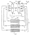
- Such an embodiment is shown in Fig. 9 under Using the reference numerals already introduced illustrated.
- the cooling mat system 2 comprises three Cooling mats 21, each of which has a separate feed 3 and one separate return 4 is connected to the distributor 7.
- the distributor 7 includes a manifold 74 connected to the flow line 71, so that coolant into the manifold as indicated by the arrow can be introduced, and a collector tube 75, which with the Return line 72 is connected so that coolant as indicated by the arrow indicated can be removed from the collector tube 75.
- the separate Feed 3 of each cooling mat 21 is in each case via a shut-off device 31, for example, a ball valve connected to the manifold 74.
- the separate return 4 of each cooling mat 21 is in each case via a shut-off device 41, for example a ball valve, is connected to the collector pipe 75.
- the Shut-off devices 31, 41 are preferably provided on the distributor 7. consequently the flow connection for the coolant can be made through any of the Open or close cooling mats 21 separately.
- Lockable inlet or Outlet openings 76 may be provided through the coolant in the Cooling circuit can be introduced or drained from the cooling circuit can.
- the distributor 7 preferably comprises one to protect the environment Collecting device, for example a collecting basin 77, for the coolant.
- Ventilation device 78 to be provided on the distributor 7 in order to prevent air pockets would deteriorate the heat transfer in the cooling mats 21 to the Dissipate environment.
- an overflow valve 79 may be provided between the Collector pipe 75 and the distributor pipe 74, that is, between the flow and Return.
- the distributor 7 is preferably arranged in a housing that is weatherproof and weatherproof, and is designed so that it both on a solid surface, e.g. B. on a meadow, as well as on snow stands safely. Fastening or anchoring means can be provided his. Furthermore, the housing of the distributor 7 can be locked with a lock secured against unauthorized access.
- the distributor 7 can of course also directly on or in the housing 57 of the Unit 5 may be arranged.
- the cooling mats 21 can be both removable and non-removable Connections to the distributor 7 be connected.
- the distributor 7 can have connections for a pressure test.
- shut-off devices 31 can protect the Environmental automatic valves can be provided in the event of a defect in the corresponding cooling mat 21 or the associated feed 3 / Close return 4 automatically and thus an unwanted escape of Prevent coolant. In the event of such a leakage, a Generates a signal that generates a visual or acoustic warning or possibly leads to the coolant pump 91 being switched off.
- the supply line 71 and the return line 72 can be used as required be laid between the unit 5 and the distributor 7.
- the lines 71, 72 can be rolled up in or on the housing 57 of the Unit 5 may be provided and preferably include in the area of their The end, which is connected to the distributor 7, the shut-off valves 81 and 82nd (Fig. 1).
- the connection between the return line 72 and the Flow line 71 and the distributor 7 or the unit 5 can each as releasable connection, for example with couplings, Screw connections or bayonet locks.
- each distributor 7 is preferably via a separate one Flow line 71 (Fig. 1, Fig. 10) and a separate return line 72 with connected to the unit 5.
- the shut-off device is then on each distributor 73, for example a ball valve, is provided to keep the coolant flow in to enable or prevent the respective distributor 7. This enables a very high variability in use.
- the device according to the invention and the method according to the invention can be used wherever snow or ice needs to be cooled, for example at critical points on slopes and ski slopes, in Halfpipes, on ski jumps.
- the invention can also be used to cool a snow bar.
- a such use is shown in Fig. 11.
- a cover layer 102 of snow is Ice or other material applied, which then the counter 103 of the Snow bar 100 forms.
- a sales area 104 can be accessed through the cooling mat 21 be cooled with.
Landscapes
- Engineering & Computer Science (AREA)
- Physics & Mathematics (AREA)
- Mechanical Engineering (AREA)
- Thermal Sciences (AREA)
- General Engineering & Computer Science (AREA)
- Architecture (AREA)
- Civil Engineering (AREA)
- Structural Engineering (AREA)
- Road Paving Structures (AREA)
Priority Applications (1)
| Application Number | Priority Date | Filing Date | Title |
|---|---|---|---|
| EP02405190A EP1344996A1 (fr) | 2002-03-12 | 2002-03-12 | Dispositif et procédé pour le refroidissement de la neige |
Applications Claiming Priority (1)
| Application Number | Priority Date | Filing Date | Title |
|---|---|---|---|
| EP02405190A EP1344996A1 (fr) | 2002-03-12 | 2002-03-12 | Dispositif et procédé pour le refroidissement de la neige |
Publications (1)
| Publication Number | Publication Date |
|---|---|
| EP1344996A1 true EP1344996A1 (fr) | 2003-09-17 |
Family
ID=27763480
Family Applications (1)
| Application Number | Title | Priority Date | Filing Date |
|---|---|---|---|
| EP02405190A Withdrawn EP1344996A1 (fr) | 2002-03-12 | 2002-03-12 | Dispositif et procédé pour le refroidissement de la neige |
Country Status (1)
| Country | Link |
|---|---|
| EP (1) | EP1344996A1 (fr) |
Cited By (2)
| Publication number | Priority date | Publication date | Assignee | Title |
|---|---|---|---|---|
| US20100314463A1 (en) * | 2009-06-11 | 2010-12-16 | Max Duplan | Heating or cooling equipment including a geothermal heat pump associated with an artificial snow production installation |
| DE102022004555A1 (de) | 2022-12-05 | 2024-06-06 | Truma Gerätetechnik GmbH & Co. KG | Vorrichtung zum Temperieren zweier Medien |
Citations (7)
| Publication number | Priority date | Publication date | Assignee | Title |
|---|---|---|---|---|
| US3485057A (en) * | 1967-12-18 | 1969-12-23 | Frick Co | Ice rink |
| US3893507A (en) * | 1971-12-02 | 1975-07-08 | Calmac Mfg Corp | Apparatus for creating and maintaining an ice slab |
| DE2450311A1 (de) * | 1974-10-16 | 1976-04-29 | Escher Wyss Gmbh | Kaeltemaschinenanlage fuer kunsteisbahn und hallenbad |
| FR2583811A1 (fr) * | 1985-06-21 | 1986-12-26 | Magnani Helmuth | Patinoire artificielle couverte a recuperation d'energie par pompes a chaleur |
| FR2679020A1 (fr) * | 1991-07-12 | 1993-01-15 | Severini Bruno | Dispositif refrigerant transportable et demontable pour etalages de marches forains. |
| US5503502A (en) * | 1994-12-08 | 1996-04-02 | Netlon Limited | Method of forming a temporary vehicle-bearing surface |
| DE19843901A1 (de) | 1998-05-11 | 1999-12-02 | Morent Ralf | Verfahren und Einrichtung zur Haltbarmachung von Schnee |
-
2002
- 2002-03-12 EP EP02405190A patent/EP1344996A1/fr not_active Withdrawn
Patent Citations (7)
| Publication number | Priority date | Publication date | Assignee | Title |
|---|---|---|---|---|
| US3485057A (en) * | 1967-12-18 | 1969-12-23 | Frick Co | Ice rink |
| US3893507A (en) * | 1971-12-02 | 1975-07-08 | Calmac Mfg Corp | Apparatus for creating and maintaining an ice slab |
| DE2450311A1 (de) * | 1974-10-16 | 1976-04-29 | Escher Wyss Gmbh | Kaeltemaschinenanlage fuer kunsteisbahn und hallenbad |
| FR2583811A1 (fr) * | 1985-06-21 | 1986-12-26 | Magnani Helmuth | Patinoire artificielle couverte a recuperation d'energie par pompes a chaleur |
| FR2679020A1 (fr) * | 1991-07-12 | 1993-01-15 | Severini Bruno | Dispositif refrigerant transportable et demontable pour etalages de marches forains. |
| US5503502A (en) * | 1994-12-08 | 1996-04-02 | Netlon Limited | Method of forming a temporary vehicle-bearing surface |
| DE19843901A1 (de) | 1998-05-11 | 1999-12-02 | Morent Ralf | Verfahren und Einrichtung zur Haltbarmachung von Schnee |
Cited By (4)
| Publication number | Priority date | Publication date | Assignee | Title |
|---|---|---|---|---|
| US20100314463A1 (en) * | 2009-06-11 | 2010-12-16 | Max Duplan | Heating or cooling equipment including a geothermal heat pump associated with an artificial snow production installation |
| WO2010142912A1 (fr) | 2009-06-11 | 2010-12-16 | Duplan, Philippe | Équipement de chauffage ou de refroidissement comportant une pompe a chaleur géothermique associée a une installation de production de neige de culture |
| FR2946734A1 (fr) * | 2009-06-11 | 2010-12-17 | Max Duplan | Equipement de chauffage ou de refroidissement comportant une pompe a chaleur geothermique associee a une installation de production de neige de culture |
| DE102022004555A1 (de) | 2022-12-05 | 2024-06-06 | Truma Gerätetechnik GmbH & Co. KG | Vorrichtung zum Temperieren zweier Medien |
Similar Documents
| Publication | Publication Date | Title |
|---|---|---|
| DE2258157A1 (de) | Verfahren und geraet zur erzeugung und aufrechterhaltung einer eisbahn | |
| CH704799A1 (de) | Rasengitter. | |
| DE102004052447A1 (de) | Energiespeicher, Wärmetauscheranordnung für einen Energiespeicher, Verfahren zum Betreiben eines Energiespeichers, Energiespeichersystem sowie Verfahren zum Betreiben eines Energiespeichersystems | |
| DE10118572B4 (de) | Wärmeversorgungssystem | |
| DE19839867C2 (de) | Verfahren zur Eiserzeugung mit einer Wärmepumpe, insbesondere zur Gebäudeklimatisierung und Kühlung von Lebensmitteln | |
| DE202011110227U1 (de) | Kombinierte Photovoltaik- und Solarthermieanlage | |
| DE60200183T2 (de) | Geothermischer Pfahl mit Hohlraum zum Durchfluss eines Fluides | |
| DE102016000176A1 (de) | Wärmetauschervorrichtung | |
| WO2018224465A1 (fr) | Système de régulateur thermique à changement d'état avec un régulateur thermique à changement d'état et procédé pour faire fonctionner un système de régulateur thermique à changement d'état | |
| AT518600A1 (de) | Sportplatzbelag | |
| EP1344996A1 (fr) | Dispositif et procédé pour le refroidissement de la neige | |
| EP1078209B1 (fr) | Procede pour la conservation de la neige | |
| WO2011107114A1 (fr) | Terrain d'équitation ou de sport à drainage et irrigation par infiltration | |
| DE202011100399U1 (de) | Vorrichtung für die Montage von Aufbauten auf einer flachen Ebene oder einer Ebene mit geringer Neigung | |
| DE2217338C3 (de) | Vorrichtung zur Enteisung, Be- und Entwässerung von Sportfeldanlagen | |
| DE19843901C2 (de) | Verfahren zur Haltbarmachung von Schnee und Kühlmatteneinrichtung zur Durchführung des Verfahrens | |
| DE102011008644A1 (de) | Vorrichtung und Verfahren zum gerichteten Gefrieren | |
| AT363962B (de) | Verfahren zum bewahren und gegebenenfalls zum herstellen von schneebedeckten flaechen | |
| DE69915825T2 (de) | Stadion mit einer umlaufenden bahn wie einer eisbahn mit umliegenden zuschauertribünen und kanalelement zum einbau in ein solches stadion | |
| DE19747588B4 (de) | Temperierbarer Flugplatzverkehrsweg und Verfahren zur Nachrüstung eines bestehenden Flugplatzverkehrsweges | |
| WO1982001386A1 (fr) | Procede pour conserver des surfaces exposees libres de glace et de neige ou pour les degeler, systeme de chauffage de surface a tubes pour la mise en oeuvre du procede, et procede de fabrication d'un tel systeme | |
| EP1764446A1 (fr) | Dispositif d'irrigation | |
| DE3813669A1 (de) | Waermepumpenanlage | |
| DE2029004A1 (de) | Einrichtung und Verfahren zur Züchtung und Pflege eines Rasens, insbesondere Sportrasens | |
| EP1318366B1 (fr) | Piste de ski couverte et procédé d'opération de celle-ci |
Legal Events
| Date | Code | Title | Description |
|---|---|---|---|
| PUAI | Public reference made under article 153(3) epc to a published international application that has entered the european phase |
Free format text: ORIGINAL CODE: 0009012 |
|
| AK | Designated contracting states |
Kind code of ref document: A1 Designated state(s): AT BE CH CY DE DK ES FI FR GB GR IE IT LI LU MC NL PT SE TR |
|
| AX | Request for extension of the european patent |
Extension state: AL LT LV MK RO SI |
|
| AKX | Designation fees paid | ||
| REG | Reference to a national code |
Ref country code: DE Ref legal event code: 8566 |
|
| STAA | Information on the status of an ep patent application or granted ep patent |
Free format text: STATUS: THE APPLICATION IS DEEMED TO BE WITHDRAWN |
|
| 18D | Application deemed to be withdrawn |
Effective date: 20040318 |