EP1344972A2 - Halterungsvorrichtung für Bildschirmgeräte - Google Patents
Halterungsvorrichtung für Bildschirmgeräte Download PDFInfo
- Publication number
- EP1344972A2 EP1344972A2 EP03251454A EP03251454A EP1344972A2 EP 1344972 A2 EP1344972 A2 EP 1344972A2 EP 03251454 A EP03251454 A EP 03251454A EP 03251454 A EP03251454 A EP 03251454A EP 1344972 A2 EP1344972 A2 EP 1344972A2
- Authority
- EP
- European Patent Office
- Prior art keywords
- support system
- arched
- coupling
- bracket
- hinge
- Prior art date
- Legal status (The legal status is an assumption and is not a legal conclusion. Google has not performed a legal analysis and makes no representation as to the accuracy of the status listed.)
- Withdrawn
Links
Images



Classifications
-
- F—MECHANICAL ENGINEERING; LIGHTING; HEATING; WEAPONS; BLASTING
- F16—ENGINEERING ELEMENTS AND UNITS; GENERAL MEASURES FOR PRODUCING AND MAINTAINING EFFECTIVE FUNCTIONING OF MACHINES OR INSTALLATIONS; THERMAL INSULATION IN GENERAL
- F16M—FRAMES, CASINGS OR BEDS OF ENGINES, MACHINES OR APPARATUS, NOT SPECIFIC TO ENGINES, MACHINES OR APPARATUS PROVIDED FOR ELSEWHERE; STANDS; SUPPORTS
- F16M11/00—Stands or trestles as supports for apparatus or articles placed thereon ; Stands for scientific apparatus such as gravitational force meters
- F16M11/02—Heads
- F16M11/04—Means for attachment of apparatus; Means allowing adjustment of the apparatus relatively to the stand
- F16M11/06—Means for attachment of apparatus; Means allowing adjustment of the apparatus relatively to the stand allowing pivoting
- F16M11/10—Means for attachment of apparatus; Means allowing adjustment of the apparatus relatively to the stand allowing pivoting around a horizontal axis
-
- F—MECHANICAL ENGINEERING; LIGHTING; HEATING; WEAPONS; BLASTING
- F16—ENGINEERING ELEMENTS AND UNITS; GENERAL MEASURES FOR PRODUCING AND MAINTAINING EFFECTIVE FUNCTIONING OF MACHINES OR INSTALLATIONS; THERMAL INSULATION IN GENERAL
- F16M—FRAMES, CASINGS OR BEDS OF ENGINES, MACHINES OR APPARATUS, NOT SPECIFIC TO ENGINES, MACHINES OR APPARATUS PROVIDED FOR ELSEWHERE; STANDS; SUPPORTS
- F16M11/00—Stands or trestles as supports for apparatus or articles placed thereon ; Stands for scientific apparatus such as gravitational force meters
- F16M11/20—Undercarriages with or without wheels
- F16M11/2007—Undercarriages with or without wheels comprising means allowing pivoting adjustment
- F16M11/2021—Undercarriages with or without wheels comprising means allowing pivoting adjustment around a horizontal axis
-
- G—PHYSICS
- G06—COMPUTING OR CALCULATING; COUNTING
- G06F—ELECTRIC DIGITAL DATA PROCESSING
- G06F1/00—Details not covered by groups G06F3/00 - G06F13/00 and G06F21/00
- G06F1/16—Constructional details or arrangements
- G06F1/1601—Constructional details related to the housing of computer displays, e.g. of CRT monitors, of flat displays
-
- F—MECHANICAL ENGINEERING; LIGHTING; HEATING; WEAPONS; BLASTING
- F16—ENGINEERING ELEMENTS AND UNITS; GENERAL MEASURES FOR PRODUCING AND MAINTAINING EFFECTIVE FUNCTIONING OF MACHINES OR INSTALLATIONS; THERMAL INSULATION IN GENERAL
- F16M—FRAMES, CASINGS OR BEDS OF ENGINES, MACHINES OR APPARATUS, NOT SPECIFIC TO ENGINES, MACHINES OR APPARATUS PROVIDED FOR ELSEWHERE; STANDS; SUPPORTS
- F16M2200/00—Details of stands or supports
- F16M2200/02—Locking means
- F16M2200/021—Locking means for rotational movement
- F16M2200/022—Locking means for rotational movement by friction
-
- F—MECHANICAL ENGINEERING; LIGHTING; HEATING; WEAPONS; BLASTING
- F16—ENGINEERING ELEMENTS AND UNITS; GENERAL MEASURES FOR PRODUCING AND MAINTAINING EFFECTIVE FUNCTIONING OF MACHINES OR INSTALLATIONS; THERMAL INSULATION IN GENERAL
- F16M—FRAMES, CASINGS OR BEDS OF ENGINES, MACHINES OR APPARATUS, NOT SPECIFIC TO ENGINES, MACHINES OR APPARATUS PROVIDED FOR ELSEWHERE; STANDS; SUPPORTS
- F16M2200/00—Details of stands or supports
- F16M2200/04—Balancing means
- F16M2200/041—Balancing means for balancing rotational movement of the head
-
- G—PHYSICS
- G06—COMPUTING OR CALCULATING; COUNTING
- G06F—ELECTRIC DIGITAL DATA PROCESSING
- G06F2200/00—Indexing scheme relating to G06F1/04 - G06F1/32
- G06F2200/16—Indexing scheme relating to G06F1/16 - G06F1/18
- G06F2200/161—Indexing scheme relating to constructional details of the monitor
- G06F2200/1612—Flat panel monitor
Definitions
- the present disclosure relates to the field of information display technology for electronic devices. Particularly, the present disclosure relates to a visual display support device having a large range of flexibility, stability, and/or storage volume.
- Information display technology has provided various forms of visual presentation for viewers.
- Cathode ray tube displays, liquid crystal displays (LCD), and/or flat panel displays are widespread and serve as the mainstay for visually displaying information.
- the decreased weight and size of a flat panel display greatly increases its versatility compared to a cathode ray tube display.
- the desire for a larger LCD viewing area has been satisfied with larger LCD displays.
- the larger LCD display although still lighter and thinner than its cathode ray tube counterpart, has created problems for the support devices used in conjunction with these displays.
- the support devices In order to accommodate the larger LCD, the support devices have become less adaptable and less flexible.
- the support devices have become harder to manipulate, limiting the range of adjustment, and therefore, the flexibility of use for the viewer.
- the support devices have become wider and thicker, occupying a larger volume of workspace proximate to the visual display. As a result, the available workspace becomes diminished. Viewers often resort to storing computer peripherals on top of the display or other awkward unstable space. Additionally, the support devices have become less stable posing a greater safety concern near the workspace.
- What is needed is a support device that has the capacity to support large displays while remaining flexible and easy to manipulate.
- the support device needs to occupy less volume and to provide greater workspace, while remaining stable and safe.
- the present invention is directed towards a support system for a display.
- the support system comprises a pair of arched bases and an arched beam coupled to the pair of arched bases.
- the support system also includes a multi-hinge rotatably coupled to the arched beam and a mounting bracket rotatably coupled with the multi-hinge wherein the mounting bracket conforms with a mounting bracket standard for mounting displays.
- the support system is a high storage volume support system.
- the arched beam of the high storage volume support system includes a first end and a second end. The first end is coupled to the first base of the pair of arched bases; the second end is coupled to the second base of the pair of arched bases.
- the high storage volume support system includes a storage volume formed by the arched beam and the pair of arched bases.
- the support system is a stable support system.
- the first arched base of the pair of arched bases of the stable support system comprises a first arch member and first web disposed between the first arch base.
- the second arched base of the pair of arched bases of the stable support system comprises a second arch member and a second web disposed between the second arch member.
- the first arched base and the second arched base are configured to stabilize the stable support system that can include a display.
- the multi-hinge of the support system comprises a body.
- the body includes a first end and a second end opposite the first end.
- the first end defines a beam axis of rotation and the second end defines a bracket axis of rotation.
- the mounting bracket is rotatably coupled to the second end of the body along the bracket axis of rotation.
- the bracket coupling includes a rotary section rotatably coupled to the second end of the body along the bracket axis and a mounting section disposed coaxially with and rotatably coupled to the rotary section.
- the multi-hinge includes a base rotatably coupled to the first end of the body about (or around) the beam axis of rotation.
- the mulit-hinge also includes a moment arm pivotally coupled to the base (or a beam coupling) at a radial distance from the beam axis and pivotally coupled to the rotary section of the bracket coupling at the radial distance from the bracket axis.
- the multi-hinge further includes a torsional preloading member coupled between the body and the base.
- Support systems are mountable to visual displays for the purpose of providing multiple positions and locations for the display to be viewed while allowing comfortable and safe viewing for the viewer without occupying large volumes of workspace.
- the support system functions utilizing an arching brace having two wide footprints for stability.
- the support system couples a unique flexing member that facilitates generous degrees of freedom and adjustment of the attached display for the viewer.
- the support system provides the flexibility, stability and safety, while minimizing the volume it occupies. With the support system, workspace peripherals can be conveniently stowed without compromising flexibility, stability or safety of the support system 10 at the workspace.
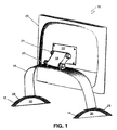
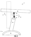
- FIGS. 1 and 2 an exemplary embodiment of a support system 10 is illustrated in a rear perspective view at FIG. 1 and a side view at FIG. 2.
- the support system 10 may be comprised of a pair of feet, or simply, a first base 12 and a second base 14.
- the first base 12 and the second base 14 are mountable to an arched beam 16.
- the first base 12 is mountable to one end of the arched beam 16 and the second base 14 is mountable to the opposite end of the arched beam 16.
- Attached proximate to the crest of the arched beam 16 is a flexing means or simply, a multi-hinge 18.
- the multi-hinge 18 is coupled to the arched beam 16 via a coupling member or simply, a beam coupling 20.
- a mounting bracket 22 is coupled to the multi-hinge 18 with a coupling member or bracket coupling 24.
- a display 26 is mounted to the mounting bracket 22.
- a flat screen display is shown as display 26 in the drawings as an exemplary embodiment.
- first base 12 can be arched base members having an arch profile.
- the arched base 12, 14 includes an arch member 28 and a web 30.
- the arch member 28 can be a rigid, robust member. The rigid and robust qualities of the arch member 28 provide the stability and safety aspects necessary to the support system 10. Also the arch shape of the feet 12, 14 provides great strength for the given material (die cast aluminum in a preferred embodiment).
- the web 30 is rigid and provides greater contact surface area for the support system 10.
- the web 30 can allow for part of the (arched base) foot 12, 14 to be suspended over an edge of a workspace surface, without a loss of stability of the support system 10 and subsequent catastrophic toppling of the display 26.
- the web 30 enhances the safety and stability of the support system 10.
- FIG. 2 further illustrates the arched beam 16 from a side view.
- This view shows that the arched beam 16 is mountable to the arched bases 12, 14 proximate to the crest of the arches, thus maximizing height.
- the height of the arched beam 16 can depend on the size of the display.
- the unique arched beam 16 allows for great strength, while maximizing the capability to store or stow peripherals underneath the support system 10.
- the arched beam 16 can be coupled to the arched bases 12, 14 through multiple coupling techniques such as welding, bonding, threaded fasteners, and the like.
- the arched beam 16 can be contiguous with the arched bases 12, 14.
- the arched beam 16 is also mountable either substantially angled or tilted. The tilt positioning is away from the display 26.
- the arched beam 16 is composed of a rigid material formed into a parabolic cross section having a thicker center and thinner edges.
- Other cross sections can be employed, such as a flat cross section, tear drop, annular, cylindrical, tubular, wedge, twist, and the like.
- the arched beam 16 provides support for the multi-hinge 18.
- the multi-hinge 18 is mountable to the arched beam 16 near the highest point on the arch structure to provide for maximum height, while maintaining maximum stability.
- the multi-hinge 18 includes a set of beam couplings 20 employed to mount the multi-hinge 18 to the arched beam 16.
- a variety of fastening means can be utilized to couple the multi-hinge 18 via the beam coupling 20 to the arched beam 16, such as welding, bonding, dowel and bore, fasteners and the like.
- the arched beam 16 and the beam coupling 20 can be contiguous in some embodiments.
- the multi-hinge 18 is coupled to a mounting bracket 22 via a bracket coupling 24.
- the bracket coupling 24 can be fixed to the mounting bracket 22 through many techniques including bonding, threadable fasteners and the like.
- the mounting bracket 22 can be a plate substantially rectilinear having dimensions that are universally mountable to a wide variety of displays 26. While the rectilinear plate is the acceptable standard, the mounting bracket 22 can be of other shapes and structures depending on the display 26 to be mounted.
- the display 26 shown as a preferred embodiment, is a flat screen display with a height of 390 millimeters and width of 588 millimeters and a depth of 2.83 inches and weighing from about 30 pounds to about 45 pounds.
- the multi-hinge 18 is configured to allow for adjustment of the display 26 relative to the arched beam 16 and arched bases 12, 14.
- the display 26 is adjustable on the multi-hinge 18 in such that a way the display 26 can be substantially horizontal.
- the flexibility of the support system 10 can be attributed in part to the unique multi-hinge 18 having more than one degree of freedom to adjust.
- a first degree of rotation 31 or (tilt) can be defined as the rotation of the display 26 about the bracket coupling 24.
- a second degree of rotation 32 (lift) can be defined as the rotation about the beam coupling 20.
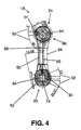
- the multi-hinge 18 includes a hinge frame or hinge body 34.
- the hinge body 34 can comprise a webbing pattern 36 with reinforcement struts 38 forming cavities 40 in order to minimize weight while maintaining strength.
- At least one hard stop 42 (means for preventing rotation) can be disposed in the hinge body 34 to limit the rotation of the couplings 20, 24.
- hard stops 42 can be included with the beam coupling 20, bracket coupling 24 and/or the hinge body 34 to limit the rotation of the couplings 20, 24.
- the hard stops 42 are formed in the hinge body 34 proximate the beam coupling 20 and the bracket coupling 24.
- the hinge body 34 further includes a first end 46 and a second end 48 opposite thereof.
- the hinge body 34 includes at least one bore 50 for rotatably receiving an axis of rotation such as a hinge pin 52.
- the hinge pin 52 is disposed through the bore 50 to provide rotary support to the beam coupling 20 disposed over the hinge pin 52 and the bracket coupling 24 disposed over the hinge pin 52.
- first beam coupling hinge pin 54 there is a first beam coupling hinge pin 54, a second beam coupling hinge pin 56, which are each disposed in separate bores 50.
- first bracket coupling hinge pin 58 and a second bracket coupling hinge pin 60 each disposed through separate bores 50 (shown in FIG. 5).
- the hinge body 34 is operatively coupled with two couplings; the beam coupling 20 and the bracket coupling 24.
- the beam coupling 20 includes two beam coupling members; a first beam coupling member 62 and a second beam coupling member 64.
- First beam coupling member 62 is rotatably coupled to the hinge body 34 proximate to the first end 46 of the hinge body 34.
- the first beam coupling member 62 is disposed over the first beam coupling hinge pin 54.
- the first beam coupling member 62 has two sections; a mounting section 66 and a rotary section 68.
- the mounting section 66 is distal from the hinge body 34 and coupled to the arched beam 16.
- the rotary section 68 is adjacent to the hinge body 34.
- the second beam coupling member 64 is rotatably coupled to the hinge body 34 opposite the first beam coupling member 62 and proximate to the first end 46 of the hinge body 34.
- the second beam coupling member 64 is disposed over the second beam coupling hinge pin 56.
- the second beam coupling member 62 has two sections; a mounting section 70 and a rotary section 72.
- the mounting section 70 is distal from the hinge body 34 and coupled to the arched beam 16.
- the rotary section 72 is adjacent to the hinge body 34.
- the rotary sections 68, 72, and corresponding rotary sections 82, 86 are substantially cylindrical in shape having a substantially circular cross section.
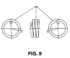
- the beam coupling 20 is at least one biasing member 74.
- the first biasing member 74 is disposed over the first beam coupling hinge pin 54
- a second biasing member 74 is disposed over the second beam coupling hinge pin 56.
- the biasing member 74 is disposed between the mounting section 66, 70 and the rotary section 68, 70 for the beam coupling members 62, 64.
- the bracket coupling 24 includes two bracket coupling members; a first bracket coupling member 76 and a second bracket coupling member 78.
- First bracket coupling member 76 is rotatably coupled to the hinge body 34 proximate to the second end 44 of the hinge body 34.
- the first bracket coupling member 76 is disposed over the first bracket coupling hinge pin 58.
- the first bracket coupling member 76 has two sections; a mounting section 80 disposed over a rotary section 82.
- the mounting section 80 can rotate relative to the rotary section 82. Rotation of the rotary section 82 also rotates the mounting section 80.
- the mounting section 80 is distal from the hinge body 34 and coupled to the mounting bracket 22.
- the rotary section 82 is adjacent the hinge body 34, in such a way that the hinge body 34 is between the mounting section 80 and the rotary section 82.
- the second bracket coupling member 78 is rotatably coupled to the hinge body 34 opposite the first bracket coupling member 76 and proximate to the second end 48 of the hinge body 34.
- the second bracket coupling member 78 is disposed over the second bracket coupling hinge pin 60.
- the second bracket coupling member 78 has two sections: a mounting section 84 disposed over a rotary section 86.
- the mounting section 84 can rotate relative to the rotary section 86. Rotation of the rotary section 86 also rotates the mounting section 84.
- the mounting section 84 is distal from the hinge body 34 and coupled to the mounting bracket 22.
- the rotary section 86 is adjacent the hinge body 34, in such a way that the hinge body 34 is between the mounting section 84 and the rotary section 86.
- bracket coupling 24 is at least one biasing member 74.
- the first biasing member 74 is disposed over the first bracket coupling hinge pin 58
- the second biasing member 74 is disposed over the second bracket coupling hinge pin 60.
- the biasing member 74 is disposed between the mounting section 80, 84 and the hinge body 34 for the bracket coupling members 76, 78.
- At least one moment arm or simply a connecting arm 88 is in cooperative communication between the beam coupling 20 and the bracket coupling 24.
- a connecting arm 88 is coupled between the first beam coupling member 62 and the first bracket coupling member 76.
- a connecting arm 88 is coupled between the second beam coupling member 64 and the second bracket coupling member 78.
- each connecting arm 88 comprises a first connecting arm member 90 and a second connecting arm member 92.
- the connecting arms 88 are coupled from each of the beam coupling member rotary sections 68, 72 to a corresponding one of the bracket coupling member rotary sections 82, 86.
- the connecting arm 88 cooperates between the beam coupling 20 and the bracket coupling 24.
- the first connecting arm member 90 can be pivotally coupled to each of the rotary sections 68, 82 and the second connecting arm member 92 can be pivotally coupled to each of the rotary sections 68, 82 respectively; each via a pivotal coupling 94.
- the pivotal coupling 94 can be a threaded fastener, such as a bolt with an allen head fitting, fastened to the rotary section 68, 82, 72 and 86 through the first connecting arm member 90 and the second connecting arm member 92. It is contemplated that other forms of pivotal coupling 94 can be substituted for the above embodiment.
- the rotary sections of the beam coupling and bracket coupling members 68, 82, 72, and 86 can be configured to receive both the first connecting arm member 90 and the second connecting arm member 92 in a pivotal manner as described above.
- each connecting arm member 90, 92 having two ends opposite each other, can be pivotally coupled to a corresponding rotary section 68, 72, and opposite thereof 82, 86, respectively.
- the pivotal couplings 94 can be arranged on the rotary section spaced apart along a diameter of the rotary section 68, 72, 82, and 86.
- the connecting arm members, 90, 92 can form a moment arm or torque 96 about the coupling hinge pins 54, 56, 58, and 60.
- the torque 96 can create a torsion force that acts between the beam coupling members 62, 64 and the bracket coupling members 76, 78.
- the relationship of the connecting arm 88 or connecting arm members 90, 92 to the torque 96 and the coupling members 62, 64, 76 and 78, are discussed further herein.
- the bracket coupling 24 is independently adjustable. For example, the bracket coupling 24 can be adjusted (tilted) in order to alter the placement of the display relative to a viewer without adjusting (rotating) the beam coupling 20.
- the beam coupling 20 is cooperatively coupled to the bracket coupling 24 by the connecting arm 88.
- the beam coupling 20 can be used to adjust the height of the mounting bracket 22 relative to the arched beam 16 and ultimately to a work surface, desktop, and the like (not shown).
- the adjustment of the beam coupling 20 is cooperatively coupled to the bracket coupling 24 in such a way that adjustment of the beam coupling 20 will not substantially alter the adjustment (tilt) of the display 26.
- the connecting arm 88 applies a torque to the bracket coupling 24 and rotates the bracket coupling 24 in such a way that the tilt of a coupled display 26 is not substantially altered.
- the beam coupling mounting sections 66, 70 are rotated, the beam coupling rotary sections 68, 72 are also rotated. Since the beam coupling rotary sections 68, 72 are cooperatively coupled via the connecting arm 88 to the bracket coupling rotary sections 82, 86, the rotation of the beam coupling rotary sections 68, 72 applies the torque 96 to the bracket coupling rotary sections 82, 86.
- the torque 96 applied to the bracket coupling rotary sections 82, 86 rotates both the bracket coupling rotary sections 82, 86 and the bracket coupling mounting sections 80, 84.
- the cooperative coupling between the beam coupling 20 and the bracket coupling 24 is such that, as the hinge body 34 adjusts relative to the beam coupling mounting sections 66, 70, that are fixed to the arched beam 16, the tilt of the display 26 is maintained. Even though the hinge body orientation is changing relative to the arched beam 16, the tilt of the display is maintained due to the adjustment to the bracket coupling 24 by the beam coupling 20 through rotation of the beam coupling rotary sections 68, 72 applying the torque 96 to the bracket coupling rotary sections 82, 86.
- a display is mounted to the mounting bracket 22 and oriented substantially vertical, (i.e., not tilted), as well as at a height of X relative to a surface, and then beam coupling 20 is adjusted in order to lower the height of the display relative to the surface.
- the adjustment to the beam coupling 20 would not substantially change the display 26 orientation to the viewer other than the height from a work surface and a minimal distance from the viewer. The display will not tilt.
- the relationship of the beam coupling rotary sections 68, 72 to the corresponding bracket coupling rotary sections 82, 86 respectively, is influenced by the first connecting arm 90 and the second connecting arm 92.
- the first beam coupling member 62 being pivotally coupled to a first connecting arm 90 and a corresponding first bracket coupling member 76 having the same first connecting arm 90 pivotally coupled at an opposite end thereof, in such a way that rotation of the first beam coupling member 62 imparts a force along the first connecting arm 90 to the first bracket coupling member 76.
- the force imparted is the torque 96 about the first bracket coupling hinge pin 58.
- the first bracket coupling member 76 is rotated about the first bracket coupling hinge pin 58.
- the rotation of the first bracket coupling member 76 actually maintains the tilt of the display as the first beam coupling member 62 is adjusted.
- This relationship is also mirrored between the first beam coupling member 62 and the first bracket coupling member 76 having the second connecting arm 92 pivotally coupled there between, for the opposite adjustment of the display (i.e., raising the height of the display from the work surface).
- the mirrored relationship exists because of the location of the pivotal coupling 94 on each rotary section being on the same diameter, but opposite thereof, relative to the coupling hinge pin 54, 56, 58, and 60.
- the connecting arm members 90 and 92 are pivotally coupled to the pivotal coupling 94 opposite each other for each rotary section on each coupling member 62, 64, 76, and 78 (see FIG. 4).
- first beam coupling member 62 and the first bracket coupling member 76 are also conceptually true for the cooperative coupling between the second beam coupling member 64 and the second bracket coupling member 78 respectively, as well as the cooperative coupling between the beam coupling 20 and the bracket coupling 24.
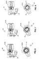
- FIGS. 6, 7 and 8 an exemplary embodiment of the bracket coupling 24 is illustrated as a plan and a side view in various stages of articulation.
- the beam coupling 20 and the bracket coupling 24 can be rotated about their associated beam and bracket coupling hinge pins 54, 56, 58 and 60.
- FIGS. 6, 7, and 8 show more detail as well as a biasing member 74 disposed in the bracket coupling 24.
- a biasing member 74 is also disposed in the beam coupling 20 (not shown). It is contemplated that multiple biasing members 74 can be employed and that the biasing members 74 can have varying degrees of strength (spring constants).
- the biasing member 74 can be preloaded such that the beam coupling 20 can hold the hinge body 34 in a predetermined position (e.g., at a 45 degree angle). Upon placement of a load such as the weight of a display 26, the multi-hinge 18 can support the display in an orientation that is comfortable for a viewer.
- the biasing member 74 can be employed to provide resistance for the tilt adjustment about the bracket coupling 24.
- FIGS. 5, 6 and 7 illustrate the range of rotation of the bracket coupling 24. The about 90 degrees of rotation is shown between FIG. 6 and FIG. 8. This rotation is relative to the hinge body 34.
- Biasing member 74 biases (provides a spring force or any resistive force opposite to the torsional forces created by the weight of components, viewers manual inputs for adjustments, and the like) the beam and bracket couplings 20, 24 in order to allow for rotation of the beam and bracket couplings 20, 24 with resistive control. It is contemplated that biasing members 74 are not the only components that can provide resistance to adjustment as discussed, hard stops and even tight tolerances between moving parts can be employed.
- the biasing member 74 can be known as a beam biasing member and/or a bracket biasing member.
- the biasing member 74 in the embodiment shown is a torsion spring configuration. There can be other configurations of the biasing member as well, such as a torsion element, friction rings, and the like.
- the torsion spring can couple with the hinge body 34 and the coupling members 62, 64, 76, and 78, as well as accommodate the coupling hinge pins 54, 56, 58 and 60 within a minimal area.
- the biasing member 74 can maintain the relationship between the hinge body 34 and the couplings 20, 24 even with a mounted load, such as a display. Additionally, the biasing member 74 in cooperation with the couplings 20, 24 can be manually manipulated lithely to allow for multiple degrees of adjustment between the couplings 20, 24 and the hinge body 34.
- the universal support system 100 includes the arched bases 112 and 114(not shown), coupled to the arched beam 116 that supports the multi-hinge 18 via the beam coupling 120.
- the multi-hinge 118 is coupled to the mounting bracket 122 via the bracket coupling 124.
- the universal support system 100 can provide support for a wide variety of displays.
- the features of the mounting bracket 122 having the length of about 200 millimeters and width of about 100 millimeters that conform to the VESA standards for flat LCD displays.
- the mounting bracket 124 includes a six threaded fastener mounting scheme.
- the multi-hinge 118 can be altered for various weights of displays and thus maintain the display in a fixed position while possessing the capability of adjusting to multiple degrees of motion with very little effort on the part of the viewer.
- the arched beam and the arched bases provide for very stable support and thus safe workspace operation of the universal support system 100.
- the multi-hinge 118 is configured to allow for adjustment of the mounting bracket 122 relative to the arched beam 116 and arched bases 112 and 114(not shown).
- the mounting bracket 122 is adjustable on the multi-hinge 118 such that the mounting bracket 122 can be substantially horizontal.
- the flexibility of the universal support system 100 can be attributed in part to the unique multi-hinge 118 having more than one degree of freedom (rotation) to adjust.
- a first degree of rotation 126 or (tilt) can be defined as the rotation about the bracket coupling 124.
- a second degree of rotation 128 (lift) can be defined as the rotation about the beam coupling 120.
- the unique arched beam 116 includes a first end 132 and a second end 134.
- the first base 112 is coupled to the first end 132, and the second base 114 is coupled to the second end 134.
- the arched beam 116 and the first and second bases 112 and 114 provide a large volume or storage volume 136.
- the storage volume 136 frees up other workspace required for tasks other than visual display activity.
- the storage volume 136 spans from one extremity proximate to the first base 112 to another extremity proximate to the second base 114 and upwards to the limits of the arched beam 116.
- the storage volume 136 can extend well behind the display 126 and underneath the display 126.
- the storage volume 136 is bounded above by the arched beam 116 and in a variable manner by the display 126 as it is adjusted.
- Computer peripherals or, simply, peripherals 138 can be readily stored inside the storage volume 136.
- Peripherals can include, but are not limited, to keyboard, mouse, speakers, pointing device, auxiliary disc drives, and the like.
- the storage volume 136 can be configured to receive a large keyboard extended with an extra UNIX keypad.
- the display 126 can be adjusted on the multi-hinge 118 to cover computer peripherals.
- the high storage volume support system retains the qualities of flexibility, and stability, while capitalizing on maximizing available storage volume (e.g., this support system remains flexible and stable, yet maximizes available storage volume).
- the high storage volume support system occupies a minimal volume of workspace while supporting large displays.
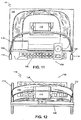
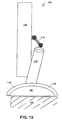
- the stable support system 180 is also configured to remain stable (not topple over) even when both or just one (or when either both or one) of the arched bases 112 and 114(not shown) is located at an edge of a surface 111.
- the stable support system 110 is configured with exceptional balance, such that the multi-hinge 116 and the display 126 can be extended or adjusted up to about 10 degrees of tilt (rotation) relative to the normal of workspace surface 111 and remain stabilized (i.e., not fall over). To put it another way, the stable support system 180 remains stable on the workspace surface 111 even after the multi-hinge 116 and the display 126 of the support system 180 has been extended or adjusted approximately about 10 degrees of tilt relative to the normal of the workspace surface 111.
- the stable support system is capable of providing a wide range of adjustment, as well as ample storage for stowing workspace peripherals, under the weight of a large display while providing stability and safety.
- the enhanced safety of having a support system that will remain standing while being adjusted over a wide range of motion is a great asset in the workplace.
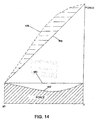
- a force diagram illustrates the features of the support system 10.
- the line represented by numeral 198 is the weight of the display.
- the line represented by numeral 158 is the torsion s/p torque line.
- the line represented by numeral 160 is the friction force for the multi-hinge 18.
- the line represented by numeral 162 is the actual force.
- the multi-hinge 18 allows for adaptable adjustment of the display 26 with very supple manipulation by a viewer. Additionally, the multi-hinge 18 provides a range of motion that allows for a wide variety of use from any type of screen attached to the support system 10.
- the force to manipulate the display 26 mounted to the support system 10 having the multi-hinge 18 can be as follows: a force to move the display 26 rearward can be from about 3.0 to 4.0 kilograms of force; the force to move the display 26 forward can be from about 2.5 to 3.5 kilograms of force.
- a force to move the display 26 rearward can be from about 3.0 to 4.0 kilograms of force
- the force to move the display 26 forward can be from about 2.5 to 3.5 kilograms of force.
- to translate the display 26 about the beam coupling 20 a distance of from about 12 centimeters to about 9.5 centimeters without tilting, about 130 kilograms per centimeter of force to about 75 kilograms per centimeter of force are required at the bracket coupling 24 and/or the beam coupling 20.
- to translate the display 26 about the beam coupling 20 a distance of from about 12 centimeters to about 9.5 centimeters without tilting, about 130 kilograms per centimeter of force are required at the bracket coupling 24 and about 75 kilograms per centimeter of force are required at the beam coupling 20.
- the multi-hinge 18 can be varied by altering tolerances; the biasing member springs constant, as well as the configuration of the multi-hinge 18.
Landscapes
- Engineering & Computer Science (AREA)
- General Engineering & Computer Science (AREA)
- Theoretical Computer Science (AREA)
- Mechanical Engineering (AREA)
- Computer Hardware Design (AREA)
- Human Computer Interaction (AREA)
- Physics & Mathematics (AREA)
- General Physics & Mathematics (AREA)
- Devices For Indicating Variable Information By Combining Individual Elements (AREA)
- Road Signs Or Road Markings (AREA)
Applications Claiming Priority (8)
| Application Number | Priority Date | Filing Date | Title |
|---|---|---|---|
| US97240 | 1987-09-15 | ||
| US96778 | 2002-03-12 | ||
| US10/097,060 US20030173476A1 (en) | 2002-03-12 | 2002-03-12 | Stable support system for displays |
| US97239 | 2002-03-12 | ||
| US97060 | 2002-03-12 | ||
| US10/097,240 US6575419B1 (en) | 2002-03-12 | 2002-03-12 | Universal support system for displays |
| US10/097,239 US6929224B1 (en) | 2002-03-12 | 2002-03-12 | Multi-hinge system for displays |
| US10/096,778 US6561469B1 (en) | 2002-03-12 | 2002-03-12 | High storage volume support for displays |
Publications (2)
| Publication Number | Publication Date |
|---|---|
| EP1344972A2 true EP1344972A2 (de) | 2003-09-17 |
| EP1344972A3 EP1344972A3 (de) | 2004-12-08 |
Family
ID=27767907
Family Applications (1)
| Application Number | Title | Priority Date | Filing Date |
|---|---|---|---|
| EP03251454A Withdrawn EP1344972A3 (de) | 2002-03-12 | 2003-03-11 | Halterungsvorrichtung für Bildschirmgeräte |
Country Status (2)
| Country | Link |
|---|---|
| EP (1) | EP1344972A3 (de) |
| JP (1) | JP2003271066A (de) |
Cited By (10)
| Publication number | Priority date | Publication date | Assignee | Title |
|---|---|---|---|---|
| WO2006095987A1 (en) * | 2005-03-08 | 2006-09-14 | Samsung Electronics Co., Ltd. | Monitor apparatus having links to move a monitor main body with respect to a base |
| EP1731825A3 (de) * | 2005-06-10 | 2007-05-09 | Markus Gerhard | Haltevorrichtung zur Anbringung eines Bildschirmes in räumlicher Zuordnung zu einer Wandesse |
| CN102954328A (zh) * | 2012-11-23 | 2013-03-06 | 苏州胜利精密制造科技股份有限公司 | 镂空式液晶电视底座 |
| US20170311464A1 (en) | 2016-04-26 | 2017-10-26 | Microsoft Technology Licensing, Llc | Structural device cover |
| WO2017213970A3 (en) * | 2016-06-10 | 2018-01-18 | Microsoft Technology Licensing, Llc | Device wiring |
| US10159158B2 (en) | 2016-04-14 | 2018-12-18 | Microsoft Technology Licensing, Llc | Device with a rotatable display |
| US10172248B1 (en) | 2016-04-14 | 2019-01-01 | Microsoft Technology Licensing, Llc | Device with a rotatable display |
| US10345851B2 (en) | 2016-04-14 | 2019-07-09 | Microsoft Technology Licensing, Llc | Device with a rotatable display |
| US10996710B2 (en) | 2016-04-14 | 2021-05-04 | Microsoft Technology Licensing, Llc | Device with a rotatable display |
| USD1119301S1 (en) * | 2024-07-30 | 2026-03-24 | Acer Incorporated | Storage device |
Families Citing this family (2)
| Publication number | Priority date | Publication date | Assignee | Title |
|---|---|---|---|---|
| JP5017467B1 (ja) | 2011-03-01 | 2012-09-05 | 株式会社東芝 | 映像表示装置 |
| JP5275497B2 (ja) * | 2012-06-06 | 2013-08-28 | 株式会社東芝 | 映像表示装置 |
Family Cites Families (5)
| Publication number | Priority date | Publication date | Assignee | Title |
|---|---|---|---|---|
| DE3228965A1 (de) * | 1982-08-03 | 1984-02-09 | Siemens AG, 1000 Berlin und 8000 München | Vorrichtung zum heben, senken und kippen einer standflaeche fuer ein geraet |
| US4560132A (en) * | 1984-10-11 | 1985-12-24 | Wilder Leslie N | Stand for display devices |
| US4989813A (en) * | 1989-11-29 | 1991-02-05 | Samsung Electron Devices Co., Ltd. | Supporting base for controlling height, swivel and inclination of display means |
| US5812368A (en) * | 1997-06-04 | 1998-09-22 | Kuo Feng Corporation | Monitor viewing angle adjusting assembly having monitor mounted on two supporting arm assemblies via turning limit assemblies |
| SE0000467L (sv) * | 2000-02-15 | 2001-05-14 | Goete Bohman | Hållaranordning för bildskärmsförsedda monitorer |
-
2003
- 2003-03-11 EP EP03251454A patent/EP1344972A3/de not_active Withdrawn
- 2003-03-12 JP JP2003066078A patent/JP2003271066A/ja active Pending
Non-Patent Citations (1)
| Title |
|---|
| None |
Cited By (15)
| Publication number | Priority date | Publication date | Assignee | Title |
|---|---|---|---|---|
| US8035957B2 (en) | 2005-03-08 | 2011-10-11 | Samsung Electronics Co., Ltd. | Monitor apparatus having links to move a monitor main body with respect to a base |
| WO2006095987A1 (en) * | 2005-03-08 | 2006-09-14 | Samsung Electronics Co., Ltd. | Monitor apparatus having links to move a monitor main body with respect to a base |
| EP1731825A3 (de) * | 2005-06-10 | 2007-05-09 | Markus Gerhard | Haltevorrichtung zur Anbringung eines Bildschirmes in räumlicher Zuordnung zu einer Wandesse |
| CN102954328A (zh) * | 2012-11-23 | 2013-03-06 | 苏州胜利精密制造科技股份有限公司 | 镂空式液晶电视底座 |
| US10345851B2 (en) | 2016-04-14 | 2019-07-09 | Microsoft Technology Licensing, Llc | Device with a rotatable display |
| US10159158B2 (en) | 2016-04-14 | 2018-12-18 | Microsoft Technology Licensing, Llc | Device with a rotatable display |
| US10172248B1 (en) | 2016-04-14 | 2019-01-01 | Microsoft Technology Licensing, Llc | Device with a rotatable display |
| US10996710B2 (en) | 2016-04-14 | 2021-05-04 | Microsoft Technology Licensing, Llc | Device with a rotatable display |
| US20170311464A1 (en) | 2016-04-26 | 2017-10-26 | Microsoft Technology Licensing, Llc | Structural device cover |
| US10999944B2 (en) | 2016-04-26 | 2021-05-04 | Microsoft Technology Licensing, Llc | Structural device cover |
| US9946309B2 (en) | 2016-06-10 | 2018-04-17 | Microsoft Technology Licensing, Llc | Device wiring |
| CN109313468A (zh) * | 2016-06-10 | 2019-02-05 | 微软技术许可有限责任公司 | 设备接线 |
| WO2017213970A3 (en) * | 2016-06-10 | 2018-01-18 | Microsoft Technology Licensing, Llc | Device wiring |
| CN109313468B (zh) * | 2016-06-10 | 2022-09-06 | 微软技术许可有限责任公司 | 设备接线 |
| USD1119301S1 (en) * | 2024-07-30 | 2026-03-24 | Acer Incorporated | Storage device |
Also Published As
| Publication number | Publication date |
|---|---|
| EP1344972A3 (de) | 2004-12-08 |
| JP2003271066A (ja) | 2003-09-25 |
Similar Documents
| Publication | Publication Date | Title |
|---|---|---|
| US6575419B1 (en) | Universal support system for displays | |
| US6929224B1 (en) | Multi-hinge system for displays | |
| US7487944B2 (en) | Flat screen monitor desktop support | |
| US7567436B2 (en) | Monitor | |
| US8035957B2 (en) | Monitor apparatus having links to move a monitor main body with respect to a base | |
| EP1344972A2 (de) | Halterungsvorrichtung für Bildschirmgeräte | |
| US7748666B2 (en) | Extension arm with moving clevis | |
| EP1237444B1 (de) | Tragarm für ein endgerät mit bildschirmanzeige | |
| US6561469B1 (en) | High storage volume support for displays | |
| US8967560B2 (en) | Cam balance mechanism systems and methods | |
| EP1626222B1 (de) | Tragvorrichtung eines Computermonitors mit flachem Bildschirm | |
| EP1492978B1 (de) | Stabilisierter berührungssensitiver flachbildschirm | |
| US20120031310A1 (en) | Ergonomically designed large display multipurpose workstation | |
| EP1821025B1 (de) | Ständer für eine Anzeigevorrichtung | |
| US10208891B2 (en) | Multi-arm display anti-toppling mechanism | |
| US20160073772A1 (en) | Bifocal display positioning apparatus and method | |
| US20030173476A1 (en) | Stable support system for displays | |
| JP3135891B2 (ja) | 液晶ディスプレイのアームスタンド | |
| US20240143023A1 (en) | Support structure for display | |
| JP2001134200A (ja) | フラットパネルディスプレイ装置 | |
| JP2008507444A (ja) | モニタ用傾き調節装置 | |
| JP3236707B2 (ja) | 自立型ディスプレイ装置 | |
| KR102772253B1 (ko) | 모니터용 듀얼 힌지장치 | |
| US20020003198A1 (en) | Angle of elevation adjusting device for display | |
| US20250251076A1 (en) | Single or dual display mounting apparatus |
Legal Events
| Date | Code | Title | Description |
|---|---|---|---|
| PUAI | Public reference made under article 153(3) epc to a published international application that has entered the european phase |
Free format text: ORIGINAL CODE: 0009012 |
|
| AK | Designated contracting states |
Kind code of ref document: A2 Designated state(s): AT BE BG CH CY CZ DE DK EE ES FI FR GB GR HU IE IT LI LU MC NL PT RO SE SI SK TR |
|
| AX | Request for extension of the european patent |
Extension state: AL LT LV MK |
|
| PUAL | Search report despatched |
Free format text: ORIGINAL CODE: 0009013 |
|
| AK | Designated contracting states |
Kind code of ref document: A3 Designated state(s): AT BE BG CH CY CZ DE DK EE ES FI FR GB GR HU IE IT LI LU MC NL PT RO SE SI SK TR |
|
| AX | Request for extension of the european patent |
Extension state: AL LT LV MK |
|
| AKX | Designation fees paid | ||
| REG | Reference to a national code |
Ref country code: DE Ref legal event code: 8566 |
|
| STAA | Information on the status of an ep patent application or granted ep patent |
Free format text: STATUS: THE APPLICATION IS DEEMED TO BE WITHDRAWN |
|
| 18D | Application deemed to be withdrawn |
Effective date: 20050609 |