EP1343020B1 - Scanning radar - Google Patents
Scanning radar Download PDFInfo
- Publication number
- EP1343020B1 EP1343020B1 EP01270784A EP01270784A EP1343020B1 EP 1343020 B1 EP1343020 B1 EP 1343020B1 EP 01270784 A EP01270784 A EP 01270784A EP 01270784 A EP01270784 A EP 01270784A EP 1343020 B1 EP1343020 B1 EP 1343020B1
- Authority
- EP
- European Patent Office
- Prior art keywords
- target
- lateral position
- correction value
- radar system
- correction
- Prior art date
- Legal status (The legal status is an assumption and is not a legal conclusion. Google has not performed a legal analysis and makes no representation as to the accuracy of the status listed.)
- Expired - Lifetime
Links
- 238000010586 diagram Methods 0.000 description 9
- 238000006073 displacement reaction Methods 0.000 description 4
- 230000000694 effects Effects 0.000 description 4
- 238000000034 method Methods 0.000 description 4
- 230000006870 function Effects 0.000 description 3
- 238000012935 Averaging Methods 0.000 description 1
- 238000004364 calculation method Methods 0.000 description 1
- 238000012886 linear function Methods 0.000 description 1
- 230000007935 neutral effect Effects 0.000 description 1
Images


Classifications
-
- G—PHYSICS
- G01—MEASURING; TESTING
- G01S—RADIO DIRECTION-FINDING; RADIO NAVIGATION; DETERMINING DISTANCE OR VELOCITY BY USE OF RADIO WAVES; LOCATING OR PRESENCE-DETECTING BY USE OF THE REFLECTION OR RERADIATION OF RADIO WAVES; ANALOGOUS ARRANGEMENTS USING OTHER WAVES
- G01S13/00—Systems using the reflection or reradiation of radio waves, e.g. radar systems; Analogous systems using reflection or reradiation of waves whose nature or wavelength is irrelevant or unspecified
- G01S13/02—Systems using reflection of radio waves, e.g. primary radar systems; Analogous systems
- G01S13/06—Systems determining position data of a target
- G01S13/42—Simultaneous measurement of distance and other co-ordinates
- G01S13/426—Scanning radar, e.g. 3D radar
-
- G—PHYSICS
- G01—MEASURING; TESTING
- G01S—RADIO DIRECTION-FINDING; RADIO NAVIGATION; DETERMINING DISTANCE OR VELOCITY BY USE OF RADIO WAVES; LOCATING OR PRESENCE-DETECTING BY USE OF THE REFLECTION OR RERADIATION OF RADIO WAVES; ANALOGOUS ARRANGEMENTS USING OTHER WAVES
- G01S13/00—Systems using the reflection or reradiation of radio waves, e.g. radar systems; Analogous systems using reflection or reradiation of waves whose nature or wavelength is irrelevant or unspecified
- G01S13/02—Systems using reflection of radio waves, e.g. primary radar systems; Analogous systems
- G01S13/06—Systems determining position data of a target
-
- G—PHYSICS
- G01—MEASURING; TESTING
- G01S—RADIO DIRECTION-FINDING; RADIO NAVIGATION; DETERMINING DISTANCE OR VELOCITY BY USE OF RADIO WAVES; LOCATING OR PRESENCE-DETECTING BY USE OF THE REFLECTION OR RERADIATION OF RADIO WAVES; ANALOGOUS ARRANGEMENTS USING OTHER WAVES
- G01S13/00—Systems using the reflection or reradiation of radio waves, e.g. radar systems; Analogous systems using reflection or reradiation of waves whose nature or wavelength is irrelevant or unspecified
- G01S13/88—Radar or analogous systems specially adapted for specific applications
- G01S13/93—Radar or analogous systems specially adapted for specific applications for anti-collision purposes
- G01S13/931—Radar or analogous systems specially adapted for specific applications for anti-collision purposes of land vehicles
-
- B—PERFORMING OPERATIONS; TRANSPORTING
- B60—VEHICLES IN GENERAL
- B60W—CONJOINT CONTROL OF VEHICLE SUB-UNITS OF DIFFERENT TYPE OR DIFFERENT FUNCTION; CONTROL SYSTEMS SPECIALLY ADAPTED FOR HYBRID VEHICLES; ROAD VEHICLE DRIVE CONTROL SYSTEMS FOR PURPOSES NOT RELATED TO THE CONTROL OF A PARTICULAR SUB-UNIT
- B60W2420/00—Indexing codes relating to the type of sensors based on the principle of their operation
- B60W2420/40—Photo, light or radio wave sensitive means, e.g. infrared sensors
- B60W2420/408—Radar; Laser, e.g. lidar
-
- B—PERFORMING OPERATIONS; TRANSPORTING
- B60—VEHICLES IN GENERAL
- B60Y—INDEXING SCHEME RELATING TO ASPECTS CROSS-CUTTING VEHICLE TECHNOLOGY
- B60Y2400/00—Special features of vehicle units
- B60Y2400/30—Sensors
- B60Y2400/301—Sensors for position or displacement
- B60Y2400/3017—Radars
-
- G—PHYSICS
- G01—MEASURING; TESTING
- G01S—RADIO DIRECTION-FINDING; RADIO NAVIGATION; DETERMINING DISTANCE OR VELOCITY BY USE OF RADIO WAVES; LOCATING OR PRESENCE-DETECTING BY USE OF THE REFLECTION OR RERADIATION OF RADIO WAVES; ANALOGOUS ARRANGEMENTS USING OTHER WAVES
- G01S13/00—Systems using the reflection or reradiation of radio waves, e.g. radar systems; Analogous systems using reflection or reradiation of waves whose nature or wavelength is irrelevant or unspecified
- G01S13/88—Radar or analogous systems specially adapted for specific applications
- G01S13/93—Radar or analogous systems specially adapted for specific applications for anti-collision purposes
- G01S13/931—Radar or analogous systems specially adapted for specific applications for anti-collision purposes of land vehicles
- G01S2013/932—Radar or analogous systems specially adapted for specific applications for anti-collision purposes of land vehicles using own vehicle data, e.g. ground speed, steering wheel direction
-
- G—PHYSICS
- G01—MEASURING; TESTING
- G01S—RADIO DIRECTION-FINDING; RADIO NAVIGATION; DETERMINING DISTANCE OR VELOCITY BY USE OF RADIO WAVES; LOCATING OR PRESENCE-DETECTING BY USE OF THE REFLECTION OR RERADIATION OF RADIO WAVES; ANALOGOUS ARRANGEMENTS USING OTHER WAVES
- G01S13/00—Systems using the reflection or reradiation of radio waves, e.g. radar systems; Analogous systems using reflection or reradiation of waves whose nature or wavelength is irrelevant or unspecified
- G01S13/88—Radar or analogous systems specially adapted for specific applications
- G01S13/93—Radar or analogous systems specially adapted for specific applications for anti-collision purposes
- G01S13/931—Radar or analogous systems specially adapted for specific applications for anti-collision purposes of land vehicles
- G01S2013/9325—Radar or analogous systems specially adapted for specific applications for anti-collision purposes of land vehicles for inter-vehicle distance regulation, e.g. navigating in platoons
Definitions
- the present invention relates to a scanning radar system that transmits radio waves while scanning the projection direction thereof, that determines the lateral position of a target based on the strength of a reflected wave returned from the target and, more particularly, to a scanning radar system that measures the lateral position of a target as well as the distance and relative velocity thereof for vehicle-to-vehicle distance control.
- a vehicle equipped with an FM-CW radar can measure the distance and relative velocity of a target located ahead of the vehicle. If the distance, for example, to a vehicle traveling ahead is to be properly controlled based on these measured values, the lateral position of the target located ahead must be determined.
- a scanning radar system transmits a radiowave while scanning the projection direction thereof, and determines the lateral position of a target based on the direction in which the target is located, i.e., the direction in which the strength of the reflected wave from the target is the highest.
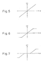
- ⁇ X increases with increasing ⁇ , but it is desirable that an upper bound be placed on the absolute value of ⁇ X as shown in Figure 6 , for reasons such as an actual vehicle width being finite. It is further desirable that a dead zone where ⁇ X is maintained at 0 be provided centered about angle 0 as shown in Figure 7 , because it is not desirable for the lateral position X to vary for small values of ⁇ due to the effect of noise. Further, when the distance to the target is large, the correction amount ⁇ X should become small; therefore, ⁇ X should be reduced in order to avoid the effect of noise.
- a scanning radar system that can accurately determine the lateral position of a target regardless of the heading of the target.
Landscapes
- Engineering & Computer Science (AREA)
- Radar, Positioning & Navigation (AREA)
- Remote Sensing (AREA)
- Physics & Mathematics (AREA)
- Computer Networks & Wireless Communication (AREA)
- General Physics & Mathematics (AREA)
- Electromagnetism (AREA)
- Radar Systems Or Details Thereof (AREA)
- Traffic Control Systems (AREA)
Description
- The present invention relates to a scanning radar system that transmits radio waves while scanning the projection direction thereof, that determines the lateral position of a target based on the strength of a reflected wave returned from the target and, more particularly, to a scanning radar system that measures the lateral position of a target as well as the distance and relative velocity thereof for vehicle-to-vehicle distance control.
- A vehicle equipped with an FM-CW radar can measure the distance and relative velocity of a target located ahead of the vehicle. If the distance, for example, to a vehicle traveling ahead is to be properly controlled based on these measured values, the lateral position of the target located ahead must be determined.
- A scanning radar system, as shown in
Figure 1(b) , transmits a radiowave while scanning the projection direction thereof, and determines the lateral position of a target based on the direction in which the target is located, i.e., the direction in which the strength of the reflected wave from the target is the highest. - According to this method, the lateral position of the target can be determined accurately, provided that there is no displacement between the direction to which the target is located when viewed from the radar-equipped vehicle (the direction to the target) and the direction in which the target is traveling (the heading of the target).
- However, if there is a displacement between the direction to the target and the heading of the target, the lateral position of the target cannot be determined accurately. For example, in the case shown in
Figure 1(a) or 1(c) , as the power of the reflected wave is the highest at one edge of the target, the lateral position of the target cannot be estimated accurately.European Patent EP-A2-0825454 discloses an example of a radar system where this is the case. - Accordingly, it is an object of the present invention to provide a scanning radar system that can accurately determine the lateral position of a target even when the heading of the target is displaced from the direction to the target.
- According to the present invention, there is provided a scanning radar system comprising: lateral position determining means for determining a lateral position X of a target, based on the strength of a reflected wave returned from the target when radio waves are projected while scanning the projection direction thereof; wherein the scanning radar system is characterised by means for determining an angle ψ between a direction to the target and a heading of the target; means for determining a correction value ΔX for the lateral position based on the angle Ψ; and means for correcting the lateral position X by the correction value ΔX, wherein said angle ψ determining means determines said angle ψ, based on a turning radius, a distance to said target, and an angle between the direction to said target and the heading of a vehicle equipped with said radar system, wherein said angle ψ determining means (16) determines said angle ψ by resolving the equation

-
-
Figure 1 is a diagram for explaining a problem in determining the lateral position; -
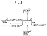
Figure 2 is a block diagram showing the configuration of a vehicle-mounted radar system according to one embodiment of the present invention; -
Figure 3 is a diagram for explaining a method of calculating the angle Ψ; -
Figure 4 is a diagram for explaining a method of calculating the angle Ψ; -
Figure 5 is a diagram for explaining how the correction value ΔX is calculated from the angle Ψ; -
Figure 6 is a diagram showing a second example explaining how the correction value ΔX is calculated from the angle Ψ; -
Figure 7 is a diagram showing a third example explaining how the correction value ΔX is calculated from the angle Ψ; -
Figure 8 is a diagram showing a first example explaining how ΔX is corrected according to the distance d or turning radius R; and -
Figure 9 is a diagram showing a second example explaining how ΔX is corrected according to the distance d or turning radius R. -
Figure 2 shows the configuration of a vehicle-mounted millimeter-wave scanning radar system as one embodiment of a scanning radar system according to the present invention. - In
Figure 2 , an ECU 10 calculates the turning radius R of the radar-equipped vehicle based on a signal from ayaw rate sensor 12 and a signal from avehicle speed sensor 14, and supplies the result to an FM-CW radar 16 together with vehicle speed data. The turning radius R can also be calculated by using data from a steering sensor instead of the data from theyaw rate sensor 12. The FM-CW radar 16 projects radio waves, in the millimeter wave region and frequency modulated by a triangular wave, in the forward direction of the vehicle and calculates the distance and relative velocity of a target located ahead. Further, the FM-CW radar 16 scans the projection direction of the radio waves, as earlier described, and calculates an estimated value X[m] for the lateral position of the target from the power distribution of the reflected wave. It also calculates a correction value ΔX for the lateral position based on the data of the turning radius R, etc. supplied from theECU 10, and supplies the corrected lateral position X to theECU 10 together with the distance and relative velocity data. Based on these data, theECU 10 generates and outputs a control signal for maintaining a constant distance from the vehicle traveling ahead. -
Figures 3 and 4 show the principles of methods for calculating the lateral position X and the correction value ΔX. InFigures 3 and 4 , R is the turning radius of the radar-equippedvehicle 20, d is the distance to thetarget 22, Ψ is the angle between the direction to which thetarget 22 is located when viewed from the vehicle 20 (the direction to the target) and the direction in which thetarget 22 is traveling (the heading of the target), and ϕ is the angle between the heading of thevehicle 20 and the heading of thetarget 22. - As can be seen from
Figure 4 , the angle ϕ can be calculated as
Hence, the angle Ψ is given as
Figure 5 . Based on the thus determined ΔX, the lateral position X is corrected as
These operations are performed using software, for example, by incorporating a CPU in the FM-CW radar. - In the function shown in
Figure 5 , ΔX increases with increasing Ψ, but it is desirable that an upper bound be placed on the absolute value of ΔX as shown inFigure 6 , for reasons such as an actual vehicle width being finite. It is further desirable that a dead zone where ΔX is maintained at 0 be provided centered about angle 0 as shown inFigure 7 , because it is not desirable for the lateral position X to vary for small values of Ψ due to the effect of noise. Further, when the distance to the target is large, the correction amount ΔX should become small; therefore, ΔX should be reduced in order to avoid the effect of noise. In this case, ΔX is multiplied by a correction coefficient that becomes smaller than 1.0 when the distance d increases, as shown by the function ofFigure 8 or 9 , and the result is taken as ΔX. Likewise, when the turning radius R is large, the correction coefficient is reduced in order to avoid the effect of noise. - Since the thus calculated ΔX contains noise, it is desirable to reduce the effect of noise by correcting X by using, for example, ΔXn calculated as

- The calculation of the correction value ΔX has been described above, but it will be understood that, depending on the target, it is desirable not to correct the lateral position if it is found for some other reason that correction of the lateral position is not necessary, even when the calculated ΔX value is not 0.
- More specifically, for a target that matches any one of the following conditions, no correction is applied because the correction is considered unnecessary even if the calculated ΔX value is not 0.
- (1) A target that is judged, from the uncorrected lateral position X, to be traveling in the same lane as the radar-equipped vehicle.
- (2) A target from which the power (peak strength) is smaller than a predetermined fixed reference value or a reference value that varies as a function of the distance. The reason is that, in the case of a small target such as a bicycle, the reflected wave (peak) is less likely to be distributed in the angular direction.
- (3) A target from which the reflected wave (peak) is not distributed in the angular direction but exhibits a peak in only one direction.
- (4) A target that has been judged to be an object, such as a large truck, physically having a plurality of reflecting points, and for which processing has been performed to take the average over a plurality of reflected waves (peaks) giving similar distances, angles, and relative velocities. The reason is that the angle is already corrected by the averaging operation and, if a further correction were applied, an overcorrection would result.
- For any target for which a correction has ever been made by determining that it does not match any one of the above conditions (1) to (4), it is desirable to always treat such a target as a target that causes an angular displacement and apply a correction, even if the target is thereafter judged to match any one of the conditions (1) to 4).
- As described above, according to the present invention, there is provided a scanning radar system that can accurately determine the lateral position of a target regardless of the heading of the target.
Claims (12)
- A scanning radar system comprising:lateral position determining means (16) for determining a lateral position X of a target (22), based on the strength of a reflected wave returned from said target when a radiowave was projected while scanning the projection direction thereofwherein the scanning radar system is characterised by:means (16) for determining an angles ψ between a direction to said target (22) and a heading of said target;means (16) for determining a correction value ΔX for said lateral position based on said angle ψ; andmeans (16) for correcting said lateral position X by said correction value ΔX, wherein said angle ψ determining means (16) determines said angle ψ, based on a turning radius (R), a distance (d) to said target (22), and an angle (θ) between the direction to said target and the heading of a vehicle (20) equipped with said radar system, wherein said angle Ψ determining means (16) determines said angle ψ by resolving the equation

- A scanning radar system according to claim 1, wherein said correction value determining means (16) determines said correction value ΔX in such a manner that an upper bound value and a lower bound value are provided for said correction value ΔX.
- A scanning radar system according to claim 1 or claim 2, wherein said correction value determining means (16) determines said correction value ΔX in such a manner that said correction value ΔX has a dead zone where said correction value ΔX does not change even if said Ψ changes within a range including 0.
- A scanning radar system according to any one of claims 1 to 3 wherein, when the distance d to said target (22) is large, said correction value determining means (16) takes a smaller value as said correction value ΔX than when the distance to said target is small.
- A scanning radar system according to any one of claims 1 to 4 wherein, when said turning radius R is large, said correction value determining means (16) takes a smaller value as said correction value ΔX than when said turning radius is small.
- A scanning radar system according to any one of claims 1 to 5 wherein, when said target (22) is judged to be traveling in the same lane as the radar-equipped vehicle (20), said correction value determining means (16) takes a smaller value as said correction value ΔX than said determined value of ΔX.
- A scanning radar system according to any one of claims 1 to 6 wherein, when the amount of change of said turning radius R within a unit time is greater than a predetermined value, said correction value determining means (16) sets said correction value ΔX to 0.
- A scanning radar system according to any one of claims 1 to 7, further comprising target discriminating means (16) for determining, for each individual target (22), whether correction of said lateral position is necessary or not, and wherein,
for any target for which said target discriminating means has determined that correction of said lateral position is not necessary, said lateral position correcting means does not correct said lateral position regardless of said determined correction value ΔX. - A scanning radar system according to claim 8 wherein, for any target (22) that has ever been determined as needing a correction to said lateral position, said lateral position correcting means (16) always correct said lateral position.
- A scanning radar system according to claim 8 or 9 wherein, for a target (22) that is judged, from the uncorrected lateral position X, to be traveling in the same lane as the radar-equipped vehicle (20), said target discriminating means (16) determines that correction of said lateral position is not necessary.
- A scanning radar system according to claim 8 to 10 wherein, for a target (22) that is judged to substantially not spread in an angular direction, said target discriminating means (16) determines that correction of said lateral position is not necessary.
- A scanning radar system according to claim 8 to 11 wherein, for a target (22) for which an average angle has been taken over a plurality of reflections, said target discriminating means (16) determines that correction of said lateral position is not necessary.
Applications Claiming Priority (5)
| Application Number | Priority Date | Filing Date | Title |
|---|---|---|---|
| JP2000377841 | 2000-12-12 | ||
| JP2000377841 | 2000-12-12 | ||
| JP2001347750 | 2001-11-13 | ||
| JP2001347750A JP3844429B2 (en) | 2000-12-12 | 2001-11-13 | Scanning radar equipment |
| PCT/JP2001/010918 WO2002048736A1 (en) | 2000-12-12 | 2001-12-12 | Scanning radar |
Publications (3)
| Publication Number | Publication Date |
|---|---|
| EP1343020A1 EP1343020A1 (en) | 2003-09-10 |
| EP1343020A4 EP1343020A4 (en) | 2005-06-29 |
| EP1343020B1 true EP1343020B1 (en) | 2008-03-12 |
Family
ID=26605689
Family Applications (1)
| Application Number | Title | Priority Date | Filing Date |
|---|---|---|---|
| EP01270784A Expired - Lifetime EP1343020B1 (en) | 2000-12-12 | 2001-12-12 | Scanning radar |
Country Status (6)
| Country | Link |
|---|---|
| US (1) | US6670911B2 (en) |
| EP (1) | EP1343020B1 (en) |
| JP (1) | JP3844429B2 (en) |
| KR (1) | KR100597344B1 (en) |
| DE (1) | DE60133216T2 (en) |
| WO (1) | WO2002048736A1 (en) |
Families Citing this family (10)
| Publication number | Priority date | Publication date | Assignee | Title |
|---|---|---|---|---|
| JP4476681B2 (en) * | 2004-04-21 | 2010-06-09 | 富士通テン株式会社 | Target identification device, target identification method, and target identification program |
| JP4265803B2 (en) * | 2005-11-22 | 2009-05-20 | 三菱電機株式会社 | Radar system |
| US7456693B2 (en) * | 2006-06-30 | 2008-11-25 | Infineon Technologies Ag | Regulation of an amplification apparatus |
| JP4769684B2 (en) * | 2006-10-12 | 2011-09-07 | 株式会社デンソーアイティーラボラトリ | Electronic scanning radar equipment |
| CN102548821B (en) * | 2010-04-07 | 2016-01-20 | 丰田自动车株式会社 | Vehicle travel support device |
| JP6056442B2 (en) * | 2012-12-11 | 2017-01-11 | 三菱電機株式会社 | Tracking antenna device |
| KR101405212B1 (en) * | 2012-12-21 | 2014-06-27 | 현대자동차 주식회사 | Calibration Target Apparatus of Radar Sensor |
| US9643735B2 (en) * | 2015-05-27 | 2017-05-09 | Honeywell International Inc. | Integration of braking action information with flight deck runway functions |
| US9412280B1 (en) * | 2015-11-05 | 2016-08-09 | Daniel Ian Zwillinger | Cooperative system and method for precise autonomous delivery |
| RU2735744C1 (en) * | 2020-03-27 | 2020-11-06 | Федеральное государственное унитарное предприятие "Ростовский-на-Дону научно-исследовательский институт радиосвязи" (ФГУП "РНИИРС") | Method for survey of single-position trilateration incoherent radar ranging of aerial targets |
Family Cites Families (6)
| Publication number | Priority date | Publication date | Assignee | Title |
|---|---|---|---|---|
| US5023617A (en) | 1990-02-20 | 1991-06-11 | General Motors Corporation | Vehicle forward sensor antenna steering system |
| SE516317C2 (en) | 1994-06-07 | 2001-12-17 | Saabtech Electronics Ab | Procedure for determining the lane of a vehicle ahead |
| JP3257410B2 (en) * | 1995-11-24 | 2002-02-18 | トヨタ自動車株式会社 | In-vehicle scanning radar |
| JP3487054B2 (en) * | 1995-12-26 | 2004-01-13 | 株式会社デンソー | Obstacle warning device for vehicles |
| JP3314623B2 (en) | 1996-08-12 | 2002-08-12 | トヨタ自動車株式会社 | In-vehicle scanning radar |
| US6269307B1 (en) * | 1998-08-06 | 2001-07-31 | Honda Giken Kogyo Kabushiki Kaisha | Travel safety system for vehicle |
-
2001
- 2001-11-13 JP JP2001347750A patent/JP3844429B2/en not_active Expired - Fee Related
- 2001-12-12 WO PCT/JP2001/010918 patent/WO2002048736A1/en active IP Right Grant
- 2001-12-12 DE DE60133216T patent/DE60133216T2/en not_active Expired - Lifetime
- 2001-12-12 KR KR1020027010269A patent/KR100597344B1/en not_active IP Right Cessation
- 2001-12-12 EP EP01270784A patent/EP1343020B1/en not_active Expired - Lifetime
- 2001-12-12 US US10/203,361 patent/US6670911B2/en not_active Expired - Lifetime
Also Published As
| Publication number | Publication date |
|---|---|
| KR100597344B1 (en) | 2006-07-10 |
| DE60133216T2 (en) | 2009-03-19 |
| KR20020076294A (en) | 2002-10-09 |
| US6670911B2 (en) | 2003-12-30 |
| JP3844429B2 (en) | 2006-11-15 |
| DE60133216D1 (en) | 2008-04-24 |
| EP1343020A4 (en) | 2005-06-29 |
| EP1343020A1 (en) | 2003-09-10 |
| WO2002048736A1 (en) | 2002-06-20 |
| JP2002243846A (en) | 2002-08-28 |
| US20030011508A1 (en) | 2003-01-16 |
Similar Documents
| Publication | Publication Date | Title |
|---|---|---|
| US6750811B2 (en) | Detection of occurrence of horizontal displacement of radar axis, determination of amount of axis displacement, and correction of axis displacement | |
| US5745070A (en) | Vehicle accurately detect an object in a lane of the radar equipped vehicle moving in a curve | |
| US6202027B1 (en) | Automatic curve sensor calibration method for an automotive CW/ICC system | |
| EP1369705B1 (en) | Signal processing method for scanning radar | |
| US8112223B2 (en) | Method for measuring lateral movements in a driver assistance system | |
| US5986601A (en) | Object detecting system for vehicle | |
| US8115669B2 (en) | Vehicular radar device | |
| US6246949B1 (en) | Apparatus for calculating deflection of central axis of an obstacle detecting apparatus mounted on a vehicle and apparatus for correcting the deflection of central axis, and system for controlling distance to a preceding vehicle traveling ahead | |
| US6768446B2 (en) | Vehicle-mounted radar apparatus providing improved accuracy of detection of lateral position of preceding vehicle | |
| US6812883B2 (en) | In-vehicle radar system | |
| US6661370B2 (en) | Radar data processing apparatus and data processing method | |
| US6643588B1 (en) | Geometric based path prediction method using moving and stop objects | |
| EP1318415B1 (en) | Mispairing determination method for FM-CW radar | |
| US20070143004A1 (en) | Road configuration recognizing system for vehicle | |
| JP2002228749A (en) | On-vehicle millimeter wave radar device | |
| EP1343020B1 (en) | Scanning radar | |
| US20200057157A1 (en) | Parking assistance device | |
| EP2100164B1 (en) | Surroundings monitoring apparatus for a motor vehicle | |
| JP2002175599A (en) | Lane position estimating device for precedent vehicle or target | |
| JPH08219799A (en) | Traveling route estimating apparatus for vehicle | |
| KR100469773B1 (en) | Method and apparatus for correcting a curve radius | |
| JPH11144198A (en) | Object identifying device for vehicle | |
| JP6480101B2 (en) | Vehicle control device | |
| JPH11125532A (en) | Advancing route estimating device for vehicle | |
| JPH06144076A (en) | Traveling controller of vehicle |
Legal Events
| Date | Code | Title | Description |
|---|---|---|---|
| PUAI | Public reference made under article 153(3) epc to a published international application that has entered the european phase |
Free format text: ORIGINAL CODE: 0009012 |
|
| 17P | Request for examination filed |
Effective date: 20020917 |
|
| AK | Designated contracting states |
Kind code of ref document: A1 Designated state(s): AT BE CH CY DE DK ES FI FR GB GR IE IT LI LU MC NL PT SE TR |
|
| RBV | Designated contracting states (corrected) |
Designated state(s): DE FR GB |
|
| A4 | Supplementary search report drawn up and despatched |
Effective date: 20050512 |
|
| GRAP | Despatch of communication of intention to grant a patent |
Free format text: ORIGINAL CODE: EPIDOSNIGR1 |
|
| GRAS | Grant fee paid |
Free format text: ORIGINAL CODE: EPIDOSNIGR3 |
|
| GRAA | (expected) grant |
Free format text: ORIGINAL CODE: 0009210 |
|
| AK | Designated contracting states |
Kind code of ref document: B1 Designated state(s): DE FR GB |
|
| REG | Reference to a national code |
Ref country code: GB Ref legal event code: FG4D |
|
| REF | Corresponds to: |
Ref document number: 60133216 Country of ref document: DE Date of ref document: 20080424 Kind code of ref document: P |
|
| ET | Fr: translation filed | ||
| PLBE | No opposition filed within time limit |
Free format text: ORIGINAL CODE: 0009261 |
|
| STAA | Information on the status of an ep patent application or granted ep patent |
Free format text: STATUS: NO OPPOSITION FILED WITHIN TIME LIMIT |
|
| 26N | No opposition filed |
Effective date: 20081215 |
|
| PGFP | Annual fee paid to national office [announced via postgrant information from national office to epo] |
Ref country code: GB Payment date: 20141210 Year of fee payment: 14 Ref country code: DE Payment date: 20141209 Year of fee payment: 14 |
|
| PGFP | Annual fee paid to national office [announced via postgrant information from national office to epo] |
Ref country code: FR Payment date: 20141208 Year of fee payment: 14 |
|
| REG | Reference to a national code |
Ref country code: DE Ref legal event code: R119 Ref document number: 60133216 Country of ref document: DE |
|
| GBPC | Gb: european patent ceased through non-payment of renewal fee |
Effective date: 20151212 |
|
| REG | Reference to a national code |
Ref country code: FR Ref legal event code: ST Effective date: 20160831 |
|
| PG25 | Lapsed in a contracting state [announced via postgrant information from national office to epo] |
Ref country code: GB Free format text: LAPSE BECAUSE OF NON-PAYMENT OF DUE FEES Effective date: 20151212 Ref country code: DE Free format text: LAPSE BECAUSE OF NON-PAYMENT OF DUE FEES Effective date: 20160701 |
|
| PG25 | Lapsed in a contracting state [announced via postgrant information from national office to epo] |
Ref country code: FR Free format text: LAPSE BECAUSE OF NON-PAYMENT OF DUE FEES Effective date: 20151231 |