EP1342978A2 - Fluggerät zur Flugzieldarstellung - Google Patents
Fluggerät zur Flugzieldarstellung Download PDFInfo
- Publication number
- EP1342978A2 EP1342978A2 EP02027813A EP02027813A EP1342978A2 EP 1342978 A2 EP1342978 A2 EP 1342978A2 EP 02027813 A EP02027813 A EP 02027813A EP 02027813 A EP02027813 A EP 02027813A EP 1342978 A2 EP1342978 A2 EP 1342978A2
- Authority
- EP
- European Patent Office
- Prior art keywords
- aircraft
- infrared radiator
- exhaust gas
- radiator
- aircraft according
- Prior art date
- Legal status (The legal status is an assumption and is not a legal conclusion. Google has not performed a legal analysis and makes no representation as to the accuracy of the status listed.)
- Granted
Links
Images

Classifications
-
- F—MECHANICAL ENGINEERING; LIGHTING; HEATING; WEAPONS; BLASTING
- F41—WEAPONS
- F41J—TARGETS; TARGET RANGES; BULLET CATCHERS
- F41J9/00—Moving targets, i.e. moving when fired at
- F41J9/08—Airborne targets, e.g. drones, kites, balloons
-
- F—MECHANICAL ENGINEERING; LIGHTING; HEATING; WEAPONS; BLASTING
- F41—WEAPONS
- F41J—TARGETS; TARGET RANGES; BULLET CATCHERS
- F41J2/00—Reflecting targets, e.g. radar-reflector targets; Active targets transmitting electromagnetic or acoustic waves
- F41J2/02—Active targets transmitting infrared radiation
Definitions
- the invention relates to an aircraft for displaying IR flight targets with at least one infrared radiator.
- Unmanned aerial vehicles are used as flight targets for the purpose of the exercise for ground / air or air / air weapon systems with infrared (IR) guidance. These aircraft can be towed missiles or drones. As far as possible, they should not only simulate the kinetic properties of real targets (e.g. combat aircraft), but also have the same infrared (IR) radiation.
- IR infrared
- Tug missiles and target drones which generate the desired IR radiation with so-called tracking flares. These have the disadvantage that they are visible in the visual and pull a smoke trail behind them. In addition, the spectral characteristics of these flares are not adapted to the radiation of the real targets. In addition, irregularities in the burning of the flares cause undesirable track problems in the IR seeker.
- a target drone is known from EP 0 876 579 B1 which generates an IR radiation by heating a burner built into the nose of the drone from the inside.
- the heated nose serves as an infrared heater.
- the disadvantage here is that the nose is strongly cooled by the wind from the outside, so that very high heating outputs are necessary to achieve sufficient IR radiation.
- an IR target missile in which the IR radiation is generated in that hot gas from the drive unit is guided with a line into the nose of the aircraft and / or the leading edge of the wing and / or in the outer pods of the aircraft is, whereby these parts are heated from the inside and thereby become an infrared heater.
- the parts which are heated from the inside are cooled by the wind from the outside, so that overall only low IR emissions can be achieved.
- the object of the invention is to provide a generic aircraft for IR flight target display which is simple and inexpensive in construction and which has a high efficiency for the IR radiation with regard to the heating power to be used.
- the aircraft according to the invention is characterized in that the infrared radiator is arranged within the exhaust gas jet of a heat-generating unit carried along, in such a way that the exhaust gas stream completely surrounds the surface of the infrared radiator exposed to the air flow.
- the aircraft can be a towed or a self-propelled aircraft.
- An advantage of the aircraft according to the invention is that the exhaust gas flow prevents the infrared radiator from cooling due to the cooling air stream. This is achieved in particular in that, according to the invention, the surface of the infrared radiator, which would otherwise be flown by the wind (air flow) during flight and would be cooled, is surrounded by the exhaust gas stream.
- the exhaust gas flow thus not only fulfills the task of heating the infrared radiator, that is to say the components which are intended to serve as infrared radiators, but the exhaust gas flow also acts as a kind of protective shield around the hot infrared radiator.
- Another advantage of the aircraft according to the invention is that by means of the infrared radiators arranged according to the invention, an IR radiation in almost any desired Direction is possible. For example, it is possible, when viewed in the direction of flight, to implement IR radiation towards the front, back and to the side.
- the heat-generating unit can advantageously be a drive unit of the aircraft or an additional burner, in particular a gas burner.
- the drive unit is expediently an aircraft gas turbine or a drive internal combustion engine.
- the IR radiator is a component that extends along the direction of propagation of the exhaust gas stream and has a cross-shaped or star-shaped cross section.
- the infrared radiator is a conical component, the axis of which extends along the direction of propagation of the exhaust gas flow.
- the infrared heater also consists of several components, e.g. several plates, in particular thin sheets, which are suitably connected to one another.
- the infrared heater advantageously consists of a temperature-resistant material, e.g. Stainless steel or ceramic. These materials can be heated to temperatures that are far above the usual expected exhaust gas temperatures of the heat-generating units.
- the exhaust gas temperatures are 400 - 800 ° C depending on the performance class (some 10 N to 100 N thrust).
- the exhaust gas from an aircraft gas turbine or an internal combustion engine is hot at the specified temperatures, but is unsuitable as an infrared radiator in the middle IR range of 3-5 ⁇ m. In this wavelength range, the exhaust gas is almost transparent, at least transversely to the beam direction, and thus hardly emits.
- the heat of the exhaust gas can therefore only be used indirectly by heating a solid which then delivers the desired IR radiation in accordance with its temperature.
- the components used as IR emitters advantageously have a surface with a high emissivity in the infrared spectral range. As a result, the radiation behavior of the components with respect to the emitted infrared wavelength range can be set. This is advantageously achieved in that the surface of the components is coated with an electrically insulating material.
- the heat transport within the material and thus the temperature distribution on the surface can be influenced in the sense of a higher IR radiation, so overall higher IR total emissions can be expected from a material with low thermal conductivity.
- the temperature of the infrared radiators and thus the IR radiation can be influenced by changing the exhaust gas temperature.
- This can e.g. when using an aircraft gas turbine as a heat-generating unit can be achieved by means of an internal control, which causes an increase in the exhaust gas temperature by changing the cross-sectional area of the outlet nozzle of the turbine.
- the IR radiation of the infrared radiators can of course also be influenced by the geometric size of the components placed in the exhaust gas stream.
- the IR radiation of the components can also be influenced by exhaust gas routing of the drive units which is matched to the components.
- the heat-generating units with the IR radiators arranged in their exhaust gas flow are fastened in front of the bow on the longitudinal axis of the aircraft and / or at the rear and / or on the wings and / or on the fuselage of the aircraft.
- the IR radiator is expediently conical or almost conical, so that there is a relatively low flow resistance.
- the bow itself is conical or approximately conical and is designed as an IR radiator.
- the IR radiator is expediently a suitable component which extends along the direction of propagation of the exhaust gas flow and a cross or has a star-shaped cross section.
- the component thus has a low flow resistance, which reduces the thrust only slightly when using a drive unit as a heat-generating unit.
- the drive units can advantageously be oriented at a predeterminable angle to the longitudinal axis of the aircraft, but in such a way that the total impulse of these drive units is directed along the longitudinal axis of the aircraft. In addition to an IR radiation component to the side, this also results in an IR radiation component to the front and to the rear (in each case seen in the flight direction of the aircraft).
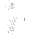
- a heat-generating unit for example an aircraft gas turbine 1, with an IR radiator 2 located in the exhaust gas stream (not shown) is shown schematically in a perspective side view.
- the IR radiator 2 is connected to the nozzle 3 of the turbine 1.
- the IR radiator 2 is designed as a so-called cross plate, i.e. thin sheets with thin walls, e.g. 0.2 - 1 mm, are connected to each other in a suitable manner, e.g. welded or inserted into each other, that the cross section of the IR radiator, as shown in the right illustration in Fig. 1, is cruciform.
- the right-hand illustration in FIG. 1 also shows that the IR radiator 2 aerodynamically fits into the exhaust gas flow from the turbine 1 and thus insignificantly reduces the thrust of the turbine.
- the IR radiator 2 is within the exhaust gas flow. The hot exhaust gas flow thus completely flows around the IR radiator 2 and heats it up. With this IR radiator 2, IR radiation in the direction of flight of the aircraft is ensured in the lateral direction as well as up and down.
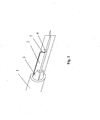
- Fig. 2 shows schematically the arrangement of Fig. 1 with a further advantageous embodiment.
- a flame holder 4 is attached to the IR radiator 2.
- the flame holder 4 it is possible to generate a flame (not shown) which heats the IR radiator 2 locally.
- the flame holder 4 can be arranged on the IR radiator 2 at a predeterminable distance from the turbine 1.
- the supply of the flame holder 4 can e.g. by means of temperature-resistant supply lines 5, which lead into the interior of the aircraft.
- To generate the flame in the flame holder 4 e.g. liquid fuel or a fuel gas can be used.
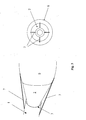
- FIG. 3 shows, in the left representation, schematically in a perspective side view a second embodiment of the arrangement of an IR radiator 2 in the exhaust gas stream of a heat-generating unit 1, for example an aircraft gas turbine.
- the turbine 1 and the IR radiator 2 are positioned axially at a predeterminable distance in front of the bow of the aircraft 6.
- the turbine 1 is connected to the fuselage of the aircraft 6 by means of support rods 7.
- the support rods 7 can in particular be designed aerodynamically, so that they form only a small flow resistance during the flight of the aircraft.
- a nozzle e.g. an annular nozzle arranged at the outlet of the turbine 1 there is usually a nozzle 3, e.g. an annular nozzle arranged at the outlet of the turbine 1 there is usually a nozzle 3, e.g. an annular nozzle arranged.
- the conical IR radiator 2 is expediently attached to the nozzle 3.
- the exhaust gas from the turbine 1 thus flows out of the ring nozzle 3 and is deflected laterally by the conical IR radiator 2, depending on the opening angle of the cone, such that a resulting thrust remains for the aircraft 6.
- the conical IR radiator 2 is heated by the exhaust gas.
- the exhaust gas thus flows over the entire cone of the IR radiator 2 and thus prevents the IR radiator from cooling down during the flight operation by the wind.
- the IR radiator 2 is a conical component which is attached to the bow of the aircraft 6.
- the bow of the aircraft 6 it is also possible for the bow of the aircraft 6 to be conical and to form the IR radiator 2. In both cases, the IR radiator 2 has only a low flow resistance.
- the right representation in FIG. 3 shows a schematic front view of the left representation. From this it can be seen that with this arrangement an IR radiation to the front, that is to say in the flight direction of the aircraft 6, is possible. The IR radiation is only slightly reduced by the turbine 1 and the support rods 7. In addition, depending on the opening angle of the cone, IR radiation to the side is also possible.
- FIG. 4 shows a side view of an aircraft according to the invention, which has, for example, an IR emitter 2a on the bow and an IR emitter 2b on the stern.
Landscapes
- Engineering & Computer Science (AREA)
- General Engineering & Computer Science (AREA)
- Remote Sensing (AREA)
- Physics & Mathematics (AREA)
- Electromagnetism (AREA)
- Radar, Positioning & Navigation (AREA)
- Aviation & Aerospace Engineering (AREA)
- Aerodynamic Tests, Hydrodynamic Tests, Wind Tunnels, And Water Tanks (AREA)
- Optical Radar Systems And Details Thereof (AREA)
- Photometry And Measurement Of Optical Pulse Characteristics (AREA)
- Resistance Heating (AREA)
- Geophysics And Detection Of Objects (AREA)
- Traffic Control Systems (AREA)
- Investigating Or Analysing Materials By Optical Means (AREA)
Abstract
Description
- Die Erfindung betrifft ein Fluggerät zur IR-Flugzieldarstellung mit mindestens einem Infrarotstrahler.
- Zum Zwecke der Übung für Boden/Luft- oder Luft/Luft-Waffensysteme mit Infrarot(IR)-Lenkung werden unbemannte Fluggeräte als Flugziele verwendet. Diese Fluggeräte können Schleppflugkörper oder Drohnen sein. Sie sollen möglichst nicht nur die kinetischen Eigenschaften der echten Ziele (z. B. Kampfflugzeuge) simulieren, sondern auch die gleiche Infrarot-(IR)-Abstrahlung aufweisen.
- Bekannt sind Schleppflugkörper und Zieldrohnen, die die gewünschte IR-Abstrahlung mit sogenannten Tracking-Flares erzeugen. Diese haben den Nachteil, dass sie im Visuellen sichtbar sind und eine Rauchfahne hinter sich her ziehen. Darüber hinaus ist die spektrale Charakteristik dieser Flares nicht an die Strahlung der echten Ziele angepaßt. Außerdem sorgen Ungleichmäßigkeiten im Abbrand der Flares für unerwünschte Track-Probleme im IR-Suchkopf.
- Aus EP 0 876 579 B1 ist eine Zieldrohne bekannt, die eine IR-Abstrahlung dadurch erzeugt, dass ein in der Nase der Drohne eingebauter Brenner die Nase von innen aufheizt. Die aufgeheizte Nase dient dabei als Infrarotstrahler. Nachteilig ist hier neben dem aufwendigen Brenneraufbau und der komplizierten Zuluft- und Abgasführung zur Sicherstellung einer stabilen Verbrennung, dass die Nase vom Fahrtwind von außen stark gekühlt wird, so dass zur Erzielung einer ausreichenden IR-Abstrahlung sehr hohe Heizleistungen notwendig sind.
- Weiterhin ist aus WO 00/29804 ein IR-Zielflugkörper bekannt, bei dem die IR-Abstrahlung dadurch erzeugt wird, dass heißes Gas aus der Antriebseinheit mit einer Leitung in die Nase des Fluggerätes und/oder die Flügelvorderkante und/oder in Außenpods des Fluggerätes geführt wird, wodurch diese Teile von innen erhitzt und dadurch zum Infrarotstrahler werden. Neben dem komplexen Aufbau ist auch hier nachteilig, dass die von innen beheizten Teile vom Fahrtwind von außen gekühlt werden, so dass insgesamt nur geringe IR-Abstrahlungen erzielbar sind.
- Aufgabe der Erfindung ist es, ein gattungsgemäßes Fluggerät zur IR-Flugzieldarstellung zu schaffen, das im Aufbau einfach und kostengünstig ist und das hinsichtlich der aufzuwendenden Heizleistung einen hohen Wirkungsgrad für die IR-Abstrahlung aufweist.
- Diese Aufgabe wird mit dem Fluggerät gemäß Anspruch 1 gelöst. Vorteilhafte Ausführungen der Erfindung sind Gegenstand von Unteransprüchen.
- Das erfindungsgemäße Fluggerät zeichnet sich dadurch aus, dass der Infrarotstrahler innerhalb des Abgasstrahls einer mitgeführten wärmeerzeugenden Einheit angeordnet ist, derart, dass der Abgasstrom die der Luftströmung ausgesetzte Oberfläche des Infrarotstrahlers vollständig umgibt. Bei dem Fluggerät kann es sich um ein geschlepptes oder ein selbstangetriebenes Fluggerät handeln.
- Ein Vorteil des erfindungsgemäßen Fluggeräts ist, dass durch den Abgasstrom eine Abkühlung des Infrarotstrahlers durch den kühlenden Fahrtwind verhindert wird. Dies wird insbesondere dadurch erreicht, dass gerade die Oberfläche des Infrarotstrahlers, die im Flugbetrieb sonst von dem Fahrtwind (Luftströmung) angeströmt wird und somit ausgekühlt werden würde, erfindungsgemäß von dem Abgasstrom umgeben wird. Der Abgasstrom erfüllt somit nicht nur die Aufgabe den Infrarotstrahler also die Bauteile, die als Infrarotstrahler dienen sollen, aufzuheizen, sondern der Abgasstrom wirkt auch als eine Art abschirmende Schutzhülle um den heißen Infrarotstrahler.
- Ein weiterer Vorteil des erfindungsgemäßen Fluggeräts ist, dass mittels der erfindungsgemäß angeordneten Infrarotstrahler eine IR-Abstrahlung in nahezu beliebiger Richtung möglich ist. So ist es z.B. möglich, jeweils in Flugrichtung gesehen, eine IR-Abstrahlung nach vorne, nach hinten und zur Seite zu realisieren.
- Die wärmeerzeugende Einheit kann vorteilhaft eine Antriebseinheit des Fluggeräts oder ein zusätzlicher Brenner, insbesondere ein Gasbrenner sein. Bei der Antriebseinheit handelt es sich zweckmäßig um eine Fluggasturbine oder um einen Antriebsverbrennungsmotor.
- In einer vorteilhaften Ausführung des erfindungsgemäßen Fluggeräts ist der IR-Strahler ein Bauteil, das sich entlang der Ausbreitungsrichtung des Abgasstroms erstreckt und einen kreuz- oder sternförmigen Querschnitt aufweist. Es ist aber auch möglich, dass in einer weiteren vorteilhaften Ausführung des erfindungsgemäßen Fluggeräts der Infrarotstrahler ein kegelförmiges Bauteil ist, dessen Achse sich entlang der Ausbreitungsrichtung des Abgasstroms erstreckt. Selbstverständlich ist es möglich, dass der Infrarotstrahler auch aus mehreren Bauteilen besteht, z.B. mehrere Platten, insbesondere dünne Bleche, die geeignet miteinander verbunden sind.
- Der Infrarotstrahler besteht vorteilhaft aus einem temperaturbeständigen Material, z.B. Edelstahl oder Keramik. Diese Materialien können auf Temperaturen aufgeheizt werden, die weit oberhalb der üblich zu erwartenden Abgastemperaturen der wärmeerzeugenden Einheiten liegen. Bei der Verwendung von z.B. Fluggasturbinen als Antriebseinheit und somit als wärmeerzeugende Einheit zur Aufheizung eines Infrarotstrahlers liegen die Abgastemperaturen je nach Leistungsklasse (einige 10 N bis 100 N Schub) bei 400 - 800 °C. Es sei hier erwähnt, dass das Abgas einer Fluggasturbine oder eines Verbrennungsmotors zwar mit den angegebenen Temperaturen heiß ist, allerdings als Infrarotstrahler im mittleren IR-Bereich von 3 - 5 um ungeeignet ist. In diesem Wellenlängenbereich ist das Abgas zumindest quer zur Strahlrichtung gesehen fast transparent und emittiert somit kaum. Die Wärme des Abgases kann also nur indirekt verwendet werden, indem ein Festkörper aufgeheizt wird, der dann entsprechend seiner Temperatur die gewünschte IR-Abstrahlung liefert.
- Die als IR-Strahler verwendeten Bauteile weisen vorteilhaft eine Oberfläche mit einem hohen Emissionsvermögen im infraroten Spektralbereich auf. Dadurch kann das Abstrahlverhalten der Bauteile hinsichtlich des abgestrahlten infraroten Wellenlängenbereichs eingestellt werden. Dies wird vorteilhaft dadurch erreicht, dass die Oberfläche der Bauteile mit einem elektrisch isolierenden Material beschichtet wird.
- Durch Änderung der Materialstärke der als IR-Strahler verwendeten Bauteile kann der Wärmetransport innerhalb des Materials und damit die Temperaturverteilung an der Oberfläche im Sinne einer höheren IR-Abstrahlung beeinflußt werden, so können von einem Material mit geringer Wärmeleitfähigkeit insgesamt höhere IR-Gesamtabstrahlungen erwartet werden.
- Außerdem kann durch Veränderung der Abgastemperatur die Temperatur der Infrarotstrahler und somit IR-Abstrahlung beeinflußt werden. Dies kann z.B. bei Verwendung einer Fluggasturbine als wärmeerzeugende Einheit mittels einer internen Steuerung erreicht werden, welche durch Änderung der Querschnittsfläche der Austrittsdüse der Turbine eine Erhöhung der Abgastemperatur bewirkt.
- Die IR-Abstrahlung der Infrarotstrahler kann selbstverständlich auch durch die geometrische Größe der in dem Abgasstrom plazierten Bauteile beeinflußt werden. Darüber hinaus kann bei Verwendung von Antriebseinheiten als wärmeerzeugende Einheiten die IR-Abstrahlung der Bauteile auch durch eine auf die Bauteile abgestimmte Abgasführung der Antriebseinheiten beeinflußt werden.
- In einer vorteilhaften Ausführung des erfindungsgemäßen Fluggeräts sind die wärmeerzeugenden Einheiten mit den in ihrem Abgasstrom angeordneten IR-Strahler vor dem Bug auf der Längsachse des Fluggeräts und/oder am Heck und/oder an den Tragflächen und/oder am Rumpf des Fluggeräts befestigt.
- Ist die wärmeerzeugende Einheit mit dem IR-Strahler vor dem Bug auf der Längsachse des Fluggeräts befestigt, so ist der IR-Strahler zweckmäßig kegelförmig oder nahezu kegelförmig ausgebildet, so dass sich ein relativ geringer Strömungswiderstand ergibt. In einer vorteilhaften Ausführung des Fluggeräts ist der Bug selbst kegelförmig oder annähernd kegelförmig und als IR-Strahler ausgebildet. Mit dieser Anordnung ist eine IR-Abstrahlung in Flugrichtung des Fluggeräts und je nach Öffnungswinkel des kegelförmigen IR-Strahlers auch in seitliche Richtung möglich.
- Ist die wärmeerzeugende Einheit mit dem IR-Strahler am Heck und/oder an den Tragflächen und/oder am Rumpf des Fluggeräts befestigt, so ist der IR-Strahler zweckmäßig ein geeignetes Bauteil, welches sich entlang der Ausbreitungsrichtung des Abgasstroms erstreckt und einen kreuz- oder sternförmigen Querschnitt aufweist. Das Bauteil weist so einen geringen Strömungswiderstand auf, was bei der Verwendung einer Antriebseinheit als wärmeerzeugende Einheit den Schub nur geringfügig verringert. Mit dieser Anordnung ist eine IR-Abstrahlung seitlich zur Flugrichtung des Fluggeräts möglich.
- Bei Verwendung von mindestens zwei Antriebseinheiten als wärmeerzeugende Einheiten, können die Antriebseinheiten vorteilhaft unter einem vorgebbaren Winkel zur Längsachse des Fluggeräts ausgerichtet sein, allerdings derart dass, der Gesamtimpuls dieser Antriebseinheiten entlang der Längsachse des Fluggeräts gerichtet ist. Dadurch ergibt sich neben einem IR-Strahlungsanteil zur Seite auch ein IR-Strahlungsanteil nach vorne und hinten (jeweils in Flugrichtung des Fluggeräts gesehen).
- Selbstverständlich ist es auch möglich, eine Antriebseinheit mit IR-Strahler vor den Bug des Fluggeräts und weitere Antriebseinheiten am oder im Rumpf des Fluggeräts vorzusehen.
- Die Erfindung sowie vorteilhafte Ausführungen der Erfindung werden anhand von Zeichnungen näher erläutert. Es zeigen:
- Fig. 1
- in perspektivischer Seitenansicht in einer ersten Ausführungsform die Anordnung eines IR-Strahlers im Abgasstrom einer wärmeerzeugenden Einheit,
- Fig. 2
- den IR-Strahler aus Fig. 1 mit einem zusätzlichen Flammhalter,
- Fig. 3
- in perspektivischer Seitenansicht in einer zweiten Ausführungsform die Anordnung eines IR-Strahlers im Abgasstrom einer wärmeerzeugenden Einheit,
- Fig. 4
- in Seitenansicht ein erfindungsgemäßes Fluggerät mit einem vor dem Bug und am Heck befindlichen IR-Strahler.
- In Fig. 1 ist in der linken Darstellung schematisch in perspektivischer Seitenansicht eine wärmeerzeugende Einheit, beispielhaft eine Fluggasturbine 1, mit einem sich im Abgasstrom (nicht dargestellt) befindlichen IR-Strahler 2 gezeigt. Der IR-Strahler 2 ist mit der Düse 3 der Turbine 1 verbunden. Selbstverständlich ist es auch möglich, unter Berücksichtigung von aerodynamischen Aspekten, den IR-Strahler 2 auf andere Art und Weise im Abgasstrahl der Turbine 1 zu positionieren, z.B. mittels Haltestangen.
- Der IR-Strahler 2 ist als sogenanntes Kreuzblech ausgeführt, d.h. dünne Bleche mit geringer Wandstärke, z.B. 0,2 - 1 mm, sind auf geeignete Weise derart miteinander verbunden, z.B. verschweißt oder auch ineinander gesteckt, dass der Querschnitt des IR-Strahlers, wie in der rechten Darstellung in Fig. 1 dargestellt, kreuzförmig ist. Die rechte Darstellung in Fig. 1 zeigt zudem, dass der IR-Strahler 2 sich aerodynamisch in den Abgasstrom der Turbine 1 einfügt und so den Schub der Turbine unwesentlich verringert. Darüber hinaus ist in beiden Darstellungen der Fig. 1 zu erkennen, dass sich der IR-Strahler 2 innerhalb des Abgasstroms befindet. Somit wird der IR-Strahler 2 vollständig von dem heißen Abgasstrom umströmt und aufgeheizt. Mit diesem IR-Strahler 2 wird in Flugrichtung des Fluggeräts gesehen eine IR-Abstrahlung in seitliche Richtung als auch nach oben und unten gewährleistet.
- Fig. 2 zeigt schematisch die Anordnung der Fig. 1 mit einer weiteren vorteilhaften Ausführung. Hierbei ist an dem IR-Strahler 2 ein Flammhalter 4 befestigt. Mittels des Flammhalters 4 ist es möglich, eine Flamme (nicht dargestellt) zu erzeugen, welche den IR-Strahler 2 lokal erwärmt. Dadurch kann die Temperatur des IR-Strahlers 2 und somit die IR-Abstrahlung individuell beeinflußt werden. Der Flammhalter 4 kann dabei am IR-Strahler 2 in einem vorgebbaren Abstand von der Turbine 1 angeordnet werden. Die Versorgung des Flammhalters 4 kann z.B. mittels temperaturbeständiger Versorgungsleitungen 5 erfolgen, die in das Innere des Fluggeräts führen. Zur Erzeugung der Flamme im Flammhalter 4 kann z.B. flüssiger Kraftstoff oder ein Brenngas verwendet werden.
- Fig. 3 zeigt in der linken Darstellung schematisch in perspektivischer Seitenansicht eine zweite Ausführungsform der Anordnung eines IR-Strahlers 2 im Abgasstrom einer wärmeerzeugenden Einheit 1, beispielhaft eine Fluggasturbine. Die Turbine 1 und der IR-Strahler 2 sind axial in einem vorgebbaren Abstand vor dem Bug des Fluggeräts 6 positioniert. Die Turbine 1 ist mittels Haltestangen 7 mit dem Rumpf des Fluggeräts 6 verbunden. Die Haltestangen 7 können insbesondere aerodynamisch ausgestaltet sein, so dass sie während des Fluges des Fluggeräts nur einen geringen Strömungswiderstand bilden.
- Am Auslass der Turbine 1 ist üblicherweise eine Düse 3, z.B. ein Ringdüse angeordnet. Der kegelförmige IR-Strahler 2 ist zweckmäßig an der Düse 3 befestigt. Das Abgas der Turbine 1 strömt somit aus der Ringdüse 3 heraus und wird von dem kegelförmigen IR-Strahler 2 je nach öffnungswinkel des Kegels seitlich derart abgelenkt, dass für das Fluggerät 6 noch ein resultierender Schub verbleibt. Gleichzeitig wird der kegelförmige IR-Strahler 2 durch das Abgas erhitzt. Das Abgas überströmt so den gesamten Kegel des IR-Strahlers 2 und verhindert so während des Flugbetriebs eine Auskühlung des IR-Strahlers durch den Fahrtwind.
- Der IR-Strahler 2 ist in dieser Darstellung ein kegelförmiges Bauteil, das auf den Bug des Fluggeräts 6 befestigt ist. Es ist aber auch möglich, dass der Bug des Fluggeräts 6 kegelförmig ausgebildet ist und den IR-Strahler 2 bildet. In beiden Fällen hat der IR-Strahler 2 nur einen geringen Strömungswiderstand.
- Die rechte Darstellung in Fig. 3 zeigt eine schematische Frontansicht der linken Darstellung. Hieraus ist zu erkennen, dass mit dieser Anordnung eine IR-Abstrahlung nach vorne, also in Flugrichtung des Fluggeräts 6 möglich ist. Die IR-Abstrahlung wird durch die Turbine 1 und die Haltestangen 7 nur unwesentlich vermindert. Darüber hinaus ist je nach Öffnungswinkel des Kegels auch eine IR-Abstrahlung zur Seite hin möglich.
- Fig. 4 zeigt in Seitenansicht ein erfindungsgemäßes Fluggerät, welches beispielhaft einen IR-Strahler 2a am Bug und einen IR-Strahler 2b am Heck aufweist.
Claims (12)
- Fluggerät zur IR-Flugzieldarstellung mit mindestens einem Infrarotstrahler (2), dadurch gekennzeichnet, dass ein Infrarotstrahler (2) innerhalb des Abgasstroms einer mitgeführten wärmeerzeugenden Einheit (1) angeordnet ist, derart, dass der Abgasstrom die, der Luftströmung ausgesetzte Oberfläche des Infrarotstrahlers (2) vollständig umgibt.
- Fluggerät nach einem der vorangehenden Ansprüche, dadurch gekennzeichnet, dass der Infrarotstrahler (2) ein Bauteil ist, das sich entlang der Ausbreitungsrichtung des Abgasstroms erstreckt und einen kreuz- oder sternförmigen Querschnitt aufweist.
- Fluggerät nach Anspruch 2, dadurch gekennzeichnet, dass an dem Infrarotstrahler (2) ein Flammhalter (4) zur lokalen Aufheizung des Infrarotstrahlers (2) vorhanden ist.
- Fluggerät nach Anspruch 1, dadurch gekennzeichnet, dass der Infrarotstrahler (2) ein kegelförmiges Bauteil ist, das sich entlang der Ausbreitungsrichtung des Abgasstroms erstreckt.
- Fluggerät nach einem der vorangehenden Ansprüche, dadurch gekennzeichnet, dass der Infrarotstrahler (2) aus einem oder mehreren temperaturbeständigen Materialien besteht.
- Fluggerät nach einem der vorangehenden Ansprüche, dadurch gekennzeichnet, dass die Oberfläche des Infrarotstrahlers (2) ein hohes Emissionsvermögen im infraroten Spektralbereich aufweist.
- Fluggerät nach Anspruch 6, dadurch gekennzeichnet, dass die Oberfläche des Infrarotstrahlers (2) mit elektrisch isolierenden Materialien beschichtet ist.
- Fluggerät nach einem der vorangehenden Ansprüche, dadurch gekennzeichnet, dass eine wärmeerzeugende Einheit (1) mit einem in ihren Abgasstrom angeordneten Infrarotstrahler (2) axial vor dem Bug und/oder am Heck und/oder an den Tragflächen des Fluggeräts und/oder am Rumpf des Fluggeräts (6) befestigt ist.
- Fluggerät nach Anspruch 8, dadurch gekennzeichnet, dass der Bug des Fluggeräts (6) kegelförmig oder annähernd kegelförmig ausgebildet ist und somit als Infrarotstrahler (2) dient.
- Fluggerät nach Anspruch 8 oder 9, dadurch gekennzeichnet, dass die sich vor dem Bug des Fluggeräts (6) befindliche wärmeerzeugende Einheit (1) mittels Haltestangen (7) an dem Rumpf des Fluggeräts (6) befestigt ist.
- Fluggerät nach einem der vorangehenden Ansprüche, dadurch gekennzeichnet, dass die wärmeerzeugende Einheit (1) eine Antriebseinheit, insbesondere eine Fluggasturbine oder ein Verbrennungsmotor ist oder ein Gasbrenner ist.
- Fluggerät nach Anspruch 11, dadurch gekennzeichnet, dass mindestens zwei Antriebseinheiten (1) vorhanden sind, die derart zueinander ausgerichtet sind, dass der Gesamtimpuls der Antriebseinheiten in Längsrichtung des Fluggeräts (6) wirkt.
Applications Claiming Priority (2)
| Application Number | Priority Date | Filing Date | Title |
|---|---|---|---|
| DE10210433A DE10210433C1 (de) | 2002-03-09 | 2002-03-09 | Fluggerät zur IR-Flugzieldarstellung |
| DE10210433 | 2002-03-09 |
Publications (3)
| Publication Number | Publication Date |
|---|---|
| EP1342978A2 true EP1342978A2 (de) | 2003-09-10 |
| EP1342978A3 EP1342978A3 (de) | 2003-11-12 |
| EP1342978B1 EP1342978B1 (de) | 2007-08-29 |
Family
ID=27588593
Family Applications (1)
| Application Number | Title | Priority Date | Filing Date |
|---|---|---|---|
| EP02027813A Expired - Lifetime EP1342978B1 (de) | 2002-03-09 | 2002-12-12 | Fluggerät zur Flugzieldarstellung |
Country Status (7)
| Country | Link |
|---|---|
| US (1) | US7048276B2 (de) |
| EP (1) | EP1342978B1 (de) |
| AT (1) | ATE371847T1 (de) |
| CA (1) | CA2421312C (de) |
| DE (2) | DE10210433C1 (de) |
| ES (1) | ES2292681T3 (de) |
| PL (1) | PL201248B1 (de) |
Cited By (1)
| Publication number | Priority date | Publication date | Assignee | Title |
|---|---|---|---|---|
| CN104297116A (zh) * | 2011-10-11 | 2015-01-21 | 波音公司 | 探测嵌入水汽云中的火山灰的系统和方法 |
Families Citing this family (4)
| Publication number | Priority date | Publication date | Assignee | Title |
|---|---|---|---|---|
| DE102006028596A1 (de) * | 2006-06-22 | 2007-12-27 | Eads Deutschland Gmbh | Flugziel |
| CN105486177B (zh) * | 2016-01-13 | 2017-03-01 | 北京金朋达航空科技有限公司 | 一种能实现大机动的靶机 |
| EP3754291B1 (de) * | 2018-11-26 | 2026-01-07 | GFA Aviation Technology Beijing Co., Ltd. | Infrarotverstärker mit steuerbarer strahlungsleistung |
| CN117441087B (zh) * | 2021-06-07 | 2026-06-30 | Tusas-土耳其航空航天工业公司 | 热轨迹增强器系统 |
Citations (2)
| Publication number | Priority date | Publication date | Assignee | Title |
|---|---|---|---|---|
| WO2000029804A1 (fr) | 1998-11-13 | 2000-05-25 | Pascal Doe | Cible a rayonnements infrarouges autopropulsee par reaction |
| EP0876579B1 (de) | 1996-01-22 | 2000-11-15 | Meggitt Defence Systems Limited | In der luft fliegendes ziel |
Family Cites Families (16)
| Publication number | Priority date | Publication date | Assignee | Title |
|---|---|---|---|---|
| US1293869A (en) * | 1918-01-21 | 1919-02-11 | Joseph B Murray | Means for guiding projectile during flight. |
| US2828603A (en) * | 1948-04-09 | 1958-04-01 | Westinghouse Electric Corp | Afterburner for turbo jet engines and the like |
| US2933317A (en) * | 1958-03-24 | 1960-04-19 | Cooper Dev Corp | Source for ray emission |
| US4044683A (en) * | 1959-08-20 | 1977-08-30 | Mcdonnell Douglas Corporation | Heat generator |
| US3001739A (en) * | 1959-10-16 | 1961-09-26 | Maxime A Faget | Aerial capsule emergency separation device |
| US3410559A (en) * | 1966-04-26 | 1968-11-12 | Hayes Internat Corp | Airborne target with infrared source |
| US3774871A (en) * | 1970-04-30 | 1973-11-27 | Us Air Force | External slurry injection for infrared enhancement of exhaust plume |
| US6140658A (en) * | 1973-02-16 | 2000-10-31 | Lockheed Martin Corporation | Combustion heated honeycomb mantle infrared radiation |
| US4063685A (en) * | 1976-07-30 | 1977-12-20 | The United States Of America As Represented By The Secretary Of The Army | Thrust vector control by circulation control over aerodynamic surfaces in a supersonic nozzle |
| US4410150A (en) * | 1980-03-03 | 1983-10-18 | General Electric Company | Drag-reducing nacelle |
| US4607849A (en) * | 1985-03-07 | 1986-08-26 | Southwest Aerospace Corporation | Jet exhaust simulator |
| US5317163A (en) * | 1990-02-26 | 1994-05-31 | Dornier Gmbh | Flying decoy |
| DE4024263C1 (en) * | 1990-07-31 | 1991-08-22 | Messerschmitt-Boelkow-Blohm Gmbh, 8012 Ottobrunn, De | IR heat radiator for location of self-propelled projectile - is positioned on tail of missile and has rotationally mounted shutter or shield in front of thermal radiator |
| FR2690411B1 (fr) * | 1992-04-27 | 1997-08-01 | Lacroix E Tous Artifices | Traceur pyrophorique et drone comportant un tel traceur. |
| US5511745A (en) * | 1994-12-30 | 1996-04-30 | Thiokol Corporation | Vectorable nozzle having jet vanes |
| US5806791A (en) * | 1995-05-26 | 1998-09-15 | Raytheon Company | Missile jet vane control system and method |
-
2002
- 2002-03-09 DE DE10210433A patent/DE10210433C1/de not_active Expired - Fee Related
- 2002-12-12 EP EP02027813A patent/EP1342978B1/de not_active Expired - Lifetime
- 2002-12-12 AT AT02027813T patent/ATE371847T1/de not_active IP Right Cessation
- 2002-12-12 ES ES02027813T patent/ES2292681T3/es not_active Expired - Lifetime
- 2002-12-12 DE DE50210806T patent/DE50210806D1/de not_active Expired - Lifetime
-
2003
- 2003-03-07 US US10/383,000 patent/US7048276B2/en not_active Expired - Lifetime
- 2003-03-07 CA CA002421312A patent/CA2421312C/en not_active Expired - Lifetime
- 2003-03-07 PL PL359054A patent/PL201248B1/pl unknown
Patent Citations (2)
| Publication number | Priority date | Publication date | Assignee | Title |
|---|---|---|---|---|
| EP0876579B1 (de) | 1996-01-22 | 2000-11-15 | Meggitt Defence Systems Limited | In der luft fliegendes ziel |
| WO2000029804A1 (fr) | 1998-11-13 | 2000-05-25 | Pascal Doe | Cible a rayonnements infrarouges autopropulsee par reaction |
Cited By (2)
| Publication number | Priority date | Publication date | Assignee | Title |
|---|---|---|---|---|
| CN104297116A (zh) * | 2011-10-11 | 2015-01-21 | 波音公司 | 探测嵌入水汽云中的火山灰的系统和方法 |
| CN104297116B (zh) * | 2011-10-11 | 2016-09-28 | 波音公司 | 探测嵌入水汽云中的火山灰的系统和方法 |
Also Published As
| Publication number | Publication date |
|---|---|
| US7048276B2 (en) | 2006-05-23 |
| PL359054A1 (en) | 2003-09-22 |
| US20030197332A1 (en) | 2003-10-23 |
| CA2421312A1 (en) | 2003-09-09 |
| ATE371847T1 (de) | 2007-09-15 |
| ES2292681T3 (es) | 2008-03-16 |
| EP1342978A3 (de) | 2003-11-12 |
| EP1342978B1 (de) | 2007-08-29 |
| DE10210433C1 (de) | 2003-08-14 |
| CA2421312C (en) | 2009-06-23 |
| DE50210806D1 (de) | 2007-10-11 |
| PL201248B1 (pl) | 2009-03-31 |
Similar Documents
| Publication | Publication Date | Title |
|---|---|---|
| DE3618185C2 (de) | Abgasvorrichtung für ein Gasturbinentriebwerk | |
| DE69703532T2 (de) | In der luft fliegendes ziel | |
| DE69719376T2 (de) | Flammenhalter für nachbrenner von gasturbinen | |
| DE69906055T2 (de) | Infrarotstrahlungsabschirmung | |
| DE887286C (de) | Nachbrennvorrichtung fuer Strahltriebwerke | |
| DE3129305C2 (de) | ||
| EP1342978B1 (de) | Fluggerät zur Flugzieldarstellung | |
| EP2928774A2 (de) | Einlauf für ein triebwerk eines luftfahrzeugs | |
| EP0238724B1 (de) | Flugkörper | |
| DE102015114648A1 (de) | Garofen mit vorrichtung zur verteilung von wasser für die erzeugung von dampf im inneren der garkammer des ofens | |
| EP0278068B1 (de) | Schubvektorsteuerung für Luftfahrzeuge | |
| DE102016101560A1 (de) | Querschubeinrichtung zur aktiven Bahn- und Lagesteuerung von Flugkörpern | |
| DE69822586T2 (de) | Luftziel | |
| DE102010024329B4 (de) | Scramjet Triebwerk mit einem dem Triebwerkseinlauf vorgeschalteten Treibstoffzufuhrmittel | |
| DE1506569C3 (de) | Kurz- oder senkrechtstartfähiges strahlgetriebenes Flugzeug | |
| DE69502921T2 (de) | Verbesserung an, mit einer Strahlmisch- und -Umlenkvorrichtung für Verbrennungsabgase ausgerüstete, Hubschrauber | |
| DE844380C (de) | Brennkammer fuer Gasturbinen | |
| DE10061772C1 (de) | Stabilisierungseinheit für einen Schleppkörper | |
| DE934996C (de) | Vortriebseinrichtung fuer Raketengeschosse | |
| EP1870663B1 (de) | Flugziel | |
| DE10347761A1 (de) | Steuerung eines Geschosses durch Plasmaentladung | |
| DE4102072A1 (de) | Verfahren und duese zum zufuehren von sekundaerluft | |
| DE878584C (de) | Thermodynamische Vortriebsduese | |
| DE2052910C3 (de) | Flugbahn-Markierungsvorrichtung | |
| DE19635851C2 (de) | Zielverfolgender Lenkflugkörper |
Legal Events
| Date | Code | Title | Description |
|---|---|---|---|
| PUAI | Public reference made under article 153(3) epc to a published international application that has entered the european phase |
Free format text: ORIGINAL CODE: 0009012 |
|
| AK | Designated contracting states |
Kind code of ref document: A2 Designated state(s): AT BE BG CH CY CZ DE DK EE ES FI FR GB GR IE IT LI LU MC NL PT SE SI SK TR |
|
| AX | Request for extension of the european patent |
Extension state: AL LT LV MK RO |
|
| PUAL | Search report despatched |
Free format text: ORIGINAL CODE: 0009013 |
|
| AK | Designated contracting states |
Kind code of ref document: A3 Designated state(s): AT BE BG CH CY CZ DE DK EE ES FI FR GB GR IE IT LI LU MC NL PT SE SI SK TR |
|
| AX | Request for extension of the european patent |
Extension state: AL LT LV MK RO |
|
| 17P | Request for examination filed |
Effective date: 20031127 |
|
| AKX | Designation fees paid |
Designated state(s): AT BE BG CH CY CZ DE DK EE ES FI FR GB GR IE IT LI LU MC NL PT SE SI SK TR |
|
| RAP1 | Party data changed (applicant data changed or rights of an application transferred) |
Owner name: EADS DEUTSCHLAND GMBH |
|
| 17Q | First examination report despatched |
Effective date: 20060710 |
|
| GRAP | Despatch of communication of intention to grant a patent |
Free format text: ORIGINAL CODE: EPIDOSNIGR1 |
|
| GRAS | Grant fee paid |
Free format text: ORIGINAL CODE: EPIDOSNIGR3 |
|
| GRAA | (expected) grant |
Free format text: ORIGINAL CODE: 0009210 |
|
| AK | Designated contracting states |
Kind code of ref document: B1 Designated state(s): AT BE BG CH CY CZ DE DK EE ES FI FR GB GR IE IT LI LU MC NL PT SE SI SK TR |
|
| REG | Reference to a national code |
Ref country code: GB Ref legal event code: FG4D Free format text: NOT ENGLISH |
|
| REG | Reference to a national code |
Ref country code: CH Ref legal event code: EP |
|
| REG | Reference to a national code |
Ref country code: IE Ref legal event code: FG4D Free format text: LANGUAGE OF EP DOCUMENT: GERMAN |
|
| REF | Corresponds to: |
Ref document number: 50210806 Country of ref document: DE Date of ref document: 20071011 Kind code of ref document: P |
|
| GBT | Gb: translation of ep patent filed (gb section 77(6)(a)/1977) |
Effective date: 20071010 |
|
| ET | Fr: translation filed | ||
| REG | Reference to a national code |
Ref country code: GR Ref legal event code: EP Ref document number: 20070403612 Country of ref document: GR |
|
| PG25 | Lapsed in a contracting state [announced via postgrant information from national office to epo] |
Ref country code: FI Free format text: LAPSE BECAUSE OF FAILURE TO SUBMIT A TRANSLATION OF THE DESCRIPTION OR TO PAY THE FEE WITHIN THE PRESCRIBED TIME-LIMIT Effective date: 20070829 Ref country code: NL Free format text: LAPSE BECAUSE OF FAILURE TO SUBMIT A TRANSLATION OF THE DESCRIPTION OR TO PAY THE FEE WITHIN THE PRESCRIBED TIME-LIMIT Effective date: 20070829 |
|
| NLV1 | Nl: lapsed or annulled due to failure to fulfill the requirements of art. 29p and 29m of the patents act | ||
| REG | Reference to a national code |
Ref country code: ES Ref legal event code: FG2A Ref document number: 2292681 Country of ref document: ES Kind code of ref document: T3 |
|
| REG | Reference to a national code |
Ref country code: IE Ref legal event code: FD4D |
|
| PG25 | Lapsed in a contracting state [announced via postgrant information from national office to epo] |
Ref country code: DK Free format text: LAPSE BECAUSE OF FAILURE TO SUBMIT A TRANSLATION OF THE DESCRIPTION OR TO PAY THE FEE WITHIN THE PRESCRIBED TIME-LIMIT Effective date: 20070829 |
|
| PG25 | Lapsed in a contracting state [announced via postgrant information from national office to epo] |
Ref country code: SK Free format text: LAPSE BECAUSE OF FAILURE TO SUBMIT A TRANSLATION OF THE DESCRIPTION OR TO PAY THE FEE WITHIN THE PRESCRIBED TIME-LIMIT Effective date: 20070829 Ref country code: PT Free format text: LAPSE BECAUSE OF FAILURE TO SUBMIT A TRANSLATION OF THE DESCRIPTION OR TO PAY THE FEE WITHIN THE PRESCRIBED TIME-LIMIT Effective date: 20080129 Ref country code: IE Free format text: LAPSE BECAUSE OF FAILURE TO SUBMIT A TRANSLATION OF THE DESCRIPTION OR TO PAY THE FEE WITHIN THE PRESCRIBED TIME-LIMIT Effective date: 20070829 Ref country code: CZ Free format text: LAPSE BECAUSE OF FAILURE TO SUBMIT A TRANSLATION OF THE DESCRIPTION OR TO PAY THE FEE WITHIN THE PRESCRIBED TIME-LIMIT Effective date: 20070829 |
|
| BERE | Be: lapsed |
Owner name: EADS DEUTSCHLAND G.M.B.H. Effective date: 20071231 |
|
| PG25 | Lapsed in a contracting state [announced via postgrant information from national office to epo] |
Ref country code: SE Free format text: LAPSE BECAUSE OF FAILURE TO SUBMIT A TRANSLATION OF THE DESCRIPTION OR TO PAY THE FEE WITHIN THE PRESCRIBED TIME-LIMIT Effective date: 20071129 |
|
| PLBE | No opposition filed within time limit |
Free format text: ORIGINAL CODE: 0009261 |
|
| STAA | Information on the status of an ep patent application or granted ep patent |
Free format text: STATUS: NO OPPOSITION FILED WITHIN TIME LIMIT |
|
| PG25 | Lapsed in a contracting state [announced via postgrant information from national office to epo] |
Ref country code: MC Free format text: LAPSE BECAUSE OF NON-PAYMENT OF DUE FEES Effective date: 20071231 |
|
| REG | Reference to a national code |
Ref country code: CH Ref legal event code: PL |
|
| 26N | No opposition filed |
Effective date: 20080530 |
|
| PG25 | Lapsed in a contracting state [announced via postgrant information from national office to epo] |
Ref country code: BE Free format text: LAPSE BECAUSE OF NON-PAYMENT OF DUE FEES Effective date: 20071231 |
|
| PG25 | Lapsed in a contracting state [announced via postgrant information from national office to epo] |
Ref country code: CH Free format text: LAPSE BECAUSE OF NON-PAYMENT OF DUE FEES Effective date: 20071231 Ref country code: LI Free format text: LAPSE BECAUSE OF NON-PAYMENT OF DUE FEES Effective date: 20071231 |
|
| PG25 | Lapsed in a contracting state [announced via postgrant information from national office to epo] |
Ref country code: EE Free format text: LAPSE BECAUSE OF FAILURE TO SUBMIT A TRANSLATION OF THE DESCRIPTION OR TO PAY THE FEE WITHIN THE PRESCRIBED TIME-LIMIT Effective date: 20070829 |
|
| PG25 | Lapsed in a contracting state [announced via postgrant information from national office to epo] |
Ref country code: AT Free format text: LAPSE BECAUSE OF NON-PAYMENT OF DUE FEES Effective date: 20071212 |
|
| PG25 | Lapsed in a contracting state [announced via postgrant information from national office to epo] |
Ref country code: SI Free format text: LAPSE BECAUSE OF FAILURE TO SUBMIT A TRANSLATION OF THE DESCRIPTION OR TO PAY THE FEE WITHIN THE PRESCRIBED TIME-LIMIT Effective date: 20070829 |
|
| PG25 | Lapsed in a contracting state [announced via postgrant information from national office to epo] |
Ref country code: CY Free format text: LAPSE BECAUSE OF FAILURE TO SUBMIT A TRANSLATION OF THE DESCRIPTION OR TO PAY THE FEE WITHIN THE PRESCRIBED TIME-LIMIT Effective date: 20070829 |
|
| PG25 | Lapsed in a contracting state [announced via postgrant information from national office to epo] |
Ref country code: BG Free format text: LAPSE BECAUSE OF FAILURE TO SUBMIT A TRANSLATION OF THE DESCRIPTION OR TO PAY THE FEE WITHIN THE PRESCRIBED TIME-LIMIT Effective date: 20071129 Ref country code: LU Free format text: LAPSE BECAUSE OF NON-PAYMENT OF DUE FEES Effective date: 20071212 |
|
| PG25 | Lapsed in a contracting state [announced via postgrant information from national office to epo] |
Ref country code: TR Free format text: LAPSE BECAUSE OF FAILURE TO SUBMIT A TRANSLATION OF THE DESCRIPTION OR TO PAY THE FEE WITHIN THE PRESCRIBED TIME-LIMIT Effective date: 20070829 |
|
| PG25 | Lapsed in a contracting state [announced via postgrant information from national office to epo] |
Ref country code: IT Free format text: LAPSE BECAUSE OF NON-PAYMENT OF DUE FEES Effective date: 20071231 |
|
| REG | Reference to a national code |
Ref country code: DE Ref legal event code: R081 Ref document number: 50210806 Country of ref document: DE Owner name: AIRBUS DEFENCE AND SPACE GMBH, DE Free format text: FORMER OWNER: EADS DEUTSCHLAND GMBH, 85521 OTTOBRUNN, DE Effective date: 20140916 |
|
| REG | Reference to a national code |
Ref country code: FR Ref legal event code: PLFP Year of fee payment: 14 |
|
| REG | Reference to a national code |
Ref country code: FR Ref legal event code: PLFP Year of fee payment: 15 |
|
| REG | Reference to a national code |
Ref country code: FR Ref legal event code: PLFP Year of fee payment: 16 |
|
| REG | Reference to a national code |
Ref country code: ES Ref legal event code: PC2A Owner name: AIRBUS DEFENCE AND SPACE GMBH Effective date: 20180528 Ref country code: ES Ref legal event code: PC2A Effective date: 20180528 |
|
| REG | Reference to a national code |
Ref country code: FR Ref legal event code: CA Effective date: 20180605 Ref country code: FR Ref legal event code: CD Owner name: EADS DEUTSCHLAND GMBH, DE Effective date: 20180605 |
|
| PGFP | Annual fee paid to national office [announced via postgrant information from national office to epo] |
Ref country code: GB Payment date: 20211221 Year of fee payment: 20 Ref country code: FR Payment date: 20211224 Year of fee payment: 20 Ref country code: DE Payment date: 20211210 Year of fee payment: 20 |
|
| PGFP | Annual fee paid to national office [announced via postgrant information from national office to epo] |
Ref country code: GR Payment date: 20211214 Year of fee payment: 20 |
|
| PGFP | Annual fee paid to national office [announced via postgrant information from national office to epo] |
Ref country code: ES Payment date: 20220218 Year of fee payment: 20 |
|
| REG | Reference to a national code |
Ref country code: DE Ref legal event code: R071 Ref document number: 50210806 Country of ref document: DE |
|
| REG | Reference to a national code |
Ref country code: GB Ref legal event code: PE20 Expiry date: 20221211 |
|
| PG25 | Lapsed in a contracting state [announced via postgrant information from national office to epo] |
Ref country code: GB Free format text: LAPSE BECAUSE OF EXPIRATION OF PROTECTION Effective date: 20221211 |
|
| REG | Reference to a national code |
Ref country code: ES Ref legal event code: FD2A Effective date: 20230426 |
|
| PG25 | Lapsed in a contracting state [announced via postgrant information from national office to epo] |
Ref country code: ES Free format text: LAPSE BECAUSE OF EXPIRATION OF PROTECTION Effective date: 20221213 |