EP1342892B1 - Kreislauf zur Kühlung von Ladeluft und Verfahren zum Betreiben eines derartigen Kreislaufs - Google Patents
Kreislauf zur Kühlung von Ladeluft und Verfahren zum Betreiben eines derartigen Kreislaufs Download PDFInfo
- Publication number
- EP1342892B1 EP1342892B1 EP03003992A EP03003992A EP1342892B1 EP 1342892 B1 EP1342892 B1 EP 1342892B1 EP 03003992 A EP03003992 A EP 03003992A EP 03003992 A EP03003992 A EP 03003992A EP 1342892 B1 EP1342892 B1 EP 1342892B1
- Authority
- EP
- European Patent Office
- Prior art keywords
- circuit
- coolant
- refrigerant
- charge air
- cooling
- Prior art date
- Legal status (The legal status is an assumption and is not a legal conclusion. Google has not performed a legal analysis and makes no representation as to the accuracy of the status listed.)
- Expired - Lifetime
Links
Images

Classifications
-
- F—MECHANICAL ENGINEERING; LIGHTING; HEATING; WEAPONS; BLASTING
- F02—COMBUSTION ENGINES; HOT-GAS OR COMBUSTION-PRODUCT ENGINE PLANTS
- F02B—INTERNAL-COMBUSTION PISTON ENGINES; COMBUSTION ENGINES IN GENERAL
- F02B37/00—Engines characterised by provision of pumps driven at least for part of the time by exhaust
-
- F—MECHANICAL ENGINEERING; LIGHTING; HEATING; WEAPONS; BLASTING
- F02—COMBUSTION ENGINES; HOT-GAS OR COMBUSTION-PRODUCT ENGINE PLANTS
- F02B—INTERNAL-COMBUSTION PISTON ENGINES; COMBUSTION ENGINES IN GENERAL
- F02B29/00—Engines characterised by provision for charging or scavenging not provided for in groups F02B25/00, F02B27/00 or F02B33/00 - F02B39/00; Details thereof
- F02B29/04—Cooling of air intake supply
-
- F—MECHANICAL ENGINEERING; LIGHTING; HEATING; WEAPONS; BLASTING
- F02—COMBUSTION ENGINES; HOT-GAS OR COMBUSTION-PRODUCT ENGINE PLANTS
- F02B—INTERNAL-COMBUSTION PISTON ENGINES; COMBUSTION ENGINES IN GENERAL
- F02B29/00—Engines characterised by provision for charging or scavenging not provided for in groups F02B25/00, F02B27/00 or F02B33/00 - F02B39/00; Details thereof
- F02B29/04—Cooling of air intake supply
- F02B29/0406—Layout of the intake air cooling or coolant circuit
- F02B29/0412—Multiple heat exchangers arranged in parallel or in series
-
- F—MECHANICAL ENGINEERING; LIGHTING; HEATING; WEAPONS; BLASTING
- F02—COMBUSTION ENGINES; HOT-GAS OR COMBUSTION-PRODUCT ENGINE PLANTS
- F02B—INTERNAL-COMBUSTION PISTON ENGINES; COMBUSTION ENGINES IN GENERAL
- F02B29/00—Engines characterised by provision for charging or scavenging not provided for in groups F02B25/00, F02B27/00 or F02B33/00 - F02B39/00; Details thereof
- F02B29/04—Cooling of air intake supply
- F02B29/0406—Layout of the intake air cooling or coolant circuit
- F02B29/0418—Layout of the intake air cooling or coolant circuit the intake air cooler having a bypass or multiple flow paths within the heat exchanger to vary the effective heat transfer surface
-
- F—MECHANICAL ENGINEERING; LIGHTING; HEATING; WEAPONS; BLASTING
- F02—COMBUSTION ENGINES; HOT-GAS OR COMBUSTION-PRODUCT ENGINE PLANTS
- F02B—INTERNAL-COMBUSTION PISTON ENGINES; COMBUSTION ENGINES IN GENERAL
- F02B29/00—Engines characterised by provision for charging or scavenging not provided for in groups F02B25/00, F02B27/00 or F02B33/00 - F02B39/00; Details thereof
- F02B29/04—Cooling of air intake supply
- F02B29/0406—Layout of the intake air cooling or coolant circuit
- F02B29/0425—Air cooled heat exchangers
-
- F—MECHANICAL ENGINEERING; LIGHTING; HEATING; WEAPONS; BLASTING
- F02—COMBUSTION ENGINES; HOT-GAS OR COMBUSTION-PRODUCT ENGINE PLANTS
- F02B—INTERNAL-COMBUSTION PISTON ENGINES; COMBUSTION ENGINES IN GENERAL
- F02B29/00—Engines characterised by provision for charging or scavenging not provided for in groups F02B25/00, F02B27/00 or F02B33/00 - F02B39/00; Details thereof
- F02B29/04—Cooling of air intake supply
- F02B29/0406—Layout of the intake air cooling or coolant circuit
- F02B29/0437—Liquid cooled heat exchangers
- F02B29/0443—Layout of the coolant or refrigerant circuit
-
- F—MECHANICAL ENGINEERING; LIGHTING; HEATING; WEAPONS; BLASTING
- F02—COMBUSTION ENGINES; HOT-GAS OR COMBUSTION-PRODUCT ENGINE PLANTS
- F02B—INTERNAL-COMBUSTION PISTON ENGINES; COMBUSTION ENGINES IN GENERAL
- F02B29/00—Engines characterised by provision for charging or scavenging not provided for in groups F02B25/00, F02B27/00 or F02B33/00 - F02B39/00; Details thereof
- F02B29/04—Cooling of air intake supply
- F02B29/045—Constructional details of the heat exchangers, e.g. pipes, plates, ribs, insulation, materials, or manufacturing and assembly
- F02B29/0456—Air cooled heat exchangers
-
- F—MECHANICAL ENGINEERING; LIGHTING; HEATING; WEAPONS; BLASTING
- F02—COMBUSTION ENGINES; HOT-GAS OR COMBUSTION-PRODUCT ENGINE PLANTS
- F02B—INTERNAL-COMBUSTION PISTON ENGINES; COMBUSTION ENGINES IN GENERAL
- F02B29/00—Engines characterised by provision for charging or scavenging not provided for in groups F02B25/00, F02B27/00 or F02B33/00 - F02B39/00; Details thereof
- F02B29/04—Cooling of air intake supply
- F02B29/045—Constructional details of the heat exchangers, e.g. pipes, plates, ribs, insulation, materials, or manufacturing and assembly
- F02B29/0462—Liquid cooled heat exchangers
-
- F—MECHANICAL ENGINEERING; LIGHTING; HEATING; WEAPONS; BLASTING
- F02—COMBUSTION ENGINES; HOT-GAS OR COMBUSTION-PRODUCT ENGINE PLANTS
- F02B—INTERNAL-COMBUSTION PISTON ENGINES; COMBUSTION ENGINES IN GENERAL
- F02B29/00—Engines characterised by provision for charging or scavenging not provided for in groups F02B25/00, F02B27/00 or F02B33/00 - F02B39/00; Details thereof
- F02B29/04—Cooling of air intake supply
- F02B29/0493—Controlling the air charge temperature
-
- F—MECHANICAL ENGINEERING; LIGHTING; HEATING; WEAPONS; BLASTING
- F01—MACHINES OR ENGINES IN GENERAL; ENGINE PLANTS IN GENERAL; STEAM ENGINES
- F01P—COOLING OF MACHINES OR ENGINES IN GENERAL; COOLING OF INTERNAL-COMBUSTION ENGINES
- F01P2060/00—Cooling circuits using auxiliaries
- F01P2060/02—Intercooler
-
- F—MECHANICAL ENGINEERING; LIGHTING; HEATING; WEAPONS; BLASTING
- F01—MACHINES OR ENGINES IN GENERAL; ENGINE PLANTS IN GENERAL; STEAM ENGINES
- F01P—COOLING OF MACHINES OR ENGINES IN GENERAL; COOLING OF INTERNAL-COMBUSTION ENGINES
- F01P9/00—Cooling having pertinent characteristics not provided for in, or of interest apart from, groups F01P1/00 - F01P7/00
- F01P9/06—Cooling having pertinent characteristics not provided for in, or of interest apart from, groups F01P1/00 - F01P7/00 by use of refrigerating apparatus, e.g. of compressor or absorber type
-
- F—MECHANICAL ENGINEERING; LIGHTING; HEATING; WEAPONS; BLASTING
- F28—HEAT EXCHANGE IN GENERAL
- F28D—HEAT-EXCHANGE APPARATUS, NOT PROVIDED FOR IN ANOTHER SUBCLASS, IN WHICH THE HEAT-EXCHANGE MEDIA DO NOT COME INTO DIRECT CONTACT
- F28D1/00—Heat-exchange apparatus having stationary conduit assemblies for one heat-exchange medium only, the media being in contact with different sides of the conduit wall, in which the other heat-exchange medium is a large body of fluid, e.g. domestic or motor car radiators
- F28D1/02—Heat-exchange apparatus having stationary conduit assemblies for one heat-exchange medium only, the media being in contact with different sides of the conduit wall, in which the other heat-exchange medium is a large body of fluid, e.g. domestic or motor car radiators with heat-exchange conduits immersed in the body of fluid
- F28D1/04—Heat-exchange apparatus having stationary conduit assemblies for one heat-exchange medium only, the media being in contact with different sides of the conduit wall, in which the other heat-exchange medium is a large body of fluid, e.g. domestic or motor car radiators with heat-exchange conduits immersed in the body of fluid with tubular conduits
- F28D1/0408—Multi-circuit heat exchangers, e.g. integrating different heat exchange sections in the same unit or heat exchangers for more than two fluids
- F28D1/0426—Multi-circuit heat exchangers, e.g. integrating different heat exchange sections in the same unit or heat exchangers for more than two fluids with units having particular arrangement relative to the large body of fluid, e.g. with interleaved units or with adjacent heat exchange units in common air flow or with units extending at an angle to each other or with units arranged around a central element
- F28D1/0435—Combination of units extending one behind the other
-
- Y—GENERAL TAGGING OF NEW TECHNOLOGICAL DEVELOPMENTS; GENERAL TAGGING OF CROSS-SECTIONAL TECHNOLOGIES SPANNING OVER SEVERAL SECTIONS OF THE IPC; TECHNICAL SUBJECTS COVERED BY FORMER USPC CROSS-REFERENCE ART COLLECTIONS [XRACs] AND DIGESTS
- Y02—TECHNOLOGIES OR APPLICATIONS FOR MITIGATION OR ADAPTATION AGAINST CLIMATE CHANGE
- Y02T—CLIMATE CHANGE MITIGATION TECHNOLOGIES RELATED TO TRANSPORTATION
- Y02T10/00—Road transport of goods or passengers
- Y02T10/10—Internal combustion engine [ICE] based vehicles
- Y02T10/12—Improving ICE efficiencies
Definitions
- the invention relates to a circuit for cooling charge air in a motor vehicle with a turbocharger according to the preamble of claim 1.
- turbochargers are used to compress the air to increase the performance of engines.
- charge air there is a heating of the air, hereinafter referred to as charge air, as a result of the compression in the turbocharger to temperatures above 150 ° C.
- air coolers are used, which are arranged in front of the cooling module and serve to cool the charge air.
- the charge air flows through a heat exchanger, which is flowed through by ambient air and thus cooled. This makes it possible to cool the charge air to a temperature which is approximately 40-80 K above the ambient air temperature.
- the cooling of the charge air takes place via a coolant circuit.
- the charge air flows close to the engine through a coolant-loaded air cooler, in which the heat is transferred to the coolant.
- the coolant is pumped through an air / coolant radiator located in the front cooling module of the vehicle. There will be the Heat is released into the ambient air, whereby the coolant-cooled charge air cooling has a higher efficiency than the air-cooled charge air cooling.
- a second cooling stage in a cycle, i. a coolant and / or refrigerant circuit, provided for cooling charge air in a motor vehicle with a turbocharger, a second cooling stage.
- a second cooling stage By such a second cooling stage, a more effective cooling of the charge air is possible.
- the charge air which is cooled to a greater extent in this way leads to an increase in engine output, since the air conditioning capacity of the air conditioning system for the interior is not fully utilized at high speeds.
- Lowering the charge air temperature to a temperature below the ambient air temperature results in reduced NOx formation since the combustion temperature can be lowered, thus also providing environmental benefits.
- the heat of the charge air for example, can be used to heat the vehicle interior.
- a coolant circuit is provided with a cooler for cooling charge air in which the coolant circuit has an evaporator, which is part of a refrigerant circuit.
- the refrigerant circuit is part of an air conditioner.
- the coolant is brought to a low temperature level via the refrigerant circuit.
- the additional evaporator can be installed in existing circuits in a relatively simple manner.
- a cooler in front of the evaporator is a cooler in which coolant is (pre) cooled by the ambient air, and after the evaporator, the cooler for the charge air.
- the evaporator is arranged at a bypass of the refrigerant circuit, which is arranged parallel to the evaporator of the air conditioner.
- the bypass preferably has an expansion valve, as well as the parallel part of the main line.
- a storage container is arranged in the coolant circuit, in which cooled coolant can be stored in order to compensate for transient braking and acceleration processes, since the refrigerant compressor is coupled to the engine speed.
- Fig. 1 shows a first embodiment in which a coolant circuit 1 is provided with a coolant having a coolant pump 2 driving the coolant in the coolant circuit 1, a radiator 3, a coolant / refrigerant evaporator 4 and a coolant / charge air cooler 5, wherein the coolant flows through the individual stations in the above-mentioned order.
- the coolant in the cooler 3 is cooled by the ambient air before it is further cooled in the coolant / refrigerant evaporator 4, preferably between 5 and 25 ° C, in the coolant / charge air cooler 5 of the charge air compressed by means of a compressor K. Extract heat before it is supplied to the motor M.
- a refrigerant circuit 11 which in turn has a refrigerant compressor 12 driving the refrigerant in the refrigerant circuit 11, a condenser 13 which cooperates with the radiator 3 of the refrigerant circuit 1, an expansion valve 14 and an air-conditioner evaporator 15.
- a bypass 16 is provided, which has a second expansion valve 17 and leads through the coolant / refrigerant evaporator 4 back to the refrigerant compressor 12. The regulation of the refrigerant by means of a arranged at the junction of the bypass 16 valve 18.
- controllable valves can be provided to one of the two parallel evaporators connected or disconnected or to be able to throttle.
- the refrigerant flows from the refrigerant compressor 12 to the condenser 13 where the refrigerant is cooled by means of the ambient air. Subsequently, the refrigerant reaches the valve 18 from which it passes to the first expansion valve 14 and the air-conditioner evaporator 15 or, depending on the position of the valve 18, via the bypass 16, ie the second expansion valve 17 and the refrigerant / refrigerant evaporator 4 and the bypass 16 is returned to the main line.
- the two evaporators 4 and 5 are arranged parallel to each other and can be individually switched on or off. Furthermore, the injected amount of refrigerant in the refrigerant circuit 11 can be regulated via the expansion valves 14 and 17. Instead of expansion valves, for example, orifice tubes (orifice tubes) can be used.
- expansion valves for example, orifice tubes (orifice tubes) can be used.
- the condenser 13 and the radiator 3 are flowed through by a fan 19 of air.
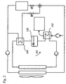
- FIG. 2 illustrated second embodiment is substantially consistent with the first embodiment, so that the same or equivalent elements are provided by 100 higher reference numerals.
- a storage container 120 is provided which serves to store cold coolant.
Landscapes
- Engineering & Computer Science (AREA)
- Chemical & Material Sciences (AREA)
- Combustion & Propulsion (AREA)
- Mechanical Engineering (AREA)
- General Engineering & Computer Science (AREA)
- Physics & Mathematics (AREA)
- Thermal Sciences (AREA)
- Air-Conditioning For Vehicles (AREA)
- Supercharger (AREA)
- Elimination Of Static Electricity (AREA)
- Control Of Electric Motors In General (AREA)
Description
- Die Erfindung betrifft einen Kreislauf zur Kühlung von Ladeluft bei einem Kraftfahrzeug mit einem Turbolader gemäß dem Oberbegriff des Anspruchs 1.
- Gemäß dem Stand der Technik werden zur Leistungssteigerung von Motoren Turbolader zur Verdichtung der Luft verwendet. Hierbei erfolgt jedoch eine Erwärmung der Luft, im Folgenden als Ladeluft bezeichnet, in Folge der Kompression im Turbolader auf Temperaturen von über 150°C. Um eine derartige Lufterwärmung zu vermindern, werden Luftkühler verwendet, die vorne im Kühlmodul angeordnet sind und zur Kühlung der Ladeluft dienen. Die Ladeluft strömt dabei durch einen Wärmeübertrager, der von Umgebungsluft durchströmt und damit gekühlt wird. Dadurch ist eine Abkühlung der Ladeluft auf eine Temperatur möglich, die etwa 40-80 K über der Temperatur der Umgebungsluft liegt.
- Ferner ist bekannt, dass die Kühlung der Ladeluft über einen Kühlmittelkreislauf erfolgt. Hierbei strömt die Ladeluft motornah durch einen kühlmittelbeaufschlagten Luftkühler, in dem die Wärme an das Kühlmittel übertragen wird. Das Kühlmittel wird durch einen Luft-/Kühlmittelkühler gepumpt, der im vorderen Kühlmodul des Fahrzeuges angeordnet ist. Dort wird die Wärme an die Umgebungsluft abgegeben, wodurch die kühlmittelgekühlte Ladeluft-Kühlung einen höheren Wirkungsgrad als die luftgekühlte Ladeluft-Kühlung aufweist.
- Es ist Aufgabe der Erfindung, einen Kreislauf der eingangs genannten Art zu verbessern.
- Diese Aufgabe wird gelöst durch einen Kreislauf mit den Merkmalen des Anspruchs 1.
- Erfindungsgemäß wird bei einem Kreislauf, d.h. einem Kühlmittel- und/oder Kältemittelkreislauf, zur Kühlung von Ladeluft bei einem Kraftfahrzeug mit einem Turbolader eine zweite Kühlstufe vorgesehen. Durch eine derartige zweite Kühlstufe ist eine effektivere Kühlung der Ladeluft möglich. Die auf diese Weise stärker abgekühlte Ladeluft führt zu einer Leistungssteigerung des Motors, da bei hohen Drehzahlen die Klimatisierungsleistung der Klimaanlage für den Innenraum nicht im vollen Umfang benötigt wird. Die Absenkung der Ladelufttemperatur auf eine Temperatur unter der Umgebungslufttemperatur führt zu einer verringerten NOx-Bildung, da die Verbrennungstemperatur abgesenkt werden kann, so dass sich auch Vorteile in Hinblick auf die Umwelt ergeben. Als Nebeneffekt kann die Wärme der Ladeluft bspw. zur Beheizung des Fahrzeuginnenraumes verwendet werden.
- Dabei wird ein Kühlmittelkreislauf mit einem Kühler zur Kühlung von Ladeluft vorgesehen bei dem der Kühlmittelkreislauf einen Verdampfer aufweist, welcher Teil eines Kältemittelkreislaufs ist. Vorzugsweise ist der Kältemittelkreislauf Teil einer Klimaanlage. Dabei wird das Kühlmittel über den Kältemittelkreislauf auf ein niedriges Temperaturniveau gebracht. Der zusätzliche Verdampfer kann auf relativ einfache Weise in bestehende Kreisläufe eingebaut werden.
- Vorzugsweise ist vor dem Verdampfer ein Kühler, worin Kühlmittel von der Umgebungsluft (vor-)gekühlt wird, und nach dem Verdampfer der Kühler für die Ladeluft angeordnet.
- Vorzugsweise ist der Verdampfer an einem Bypass des Kältemittelkreislaufs angeordnet, welcher parallel zum Verdampfer der Klimaanlage angeordnet ist. Der Bypass weist vorzugsweise ein Expansionsventil auf, ebenso wie der hierzu parallele Teil der Hauptleitung.
- Gemäß einer bevorzugten Ausführungsform ist im Kühlmittelkreislauf ein Bevorratungsbehälter angeordnet, in dem abgekühltes Kühlmittel gespeichert werden kann, um instationäre Brems- und Beschleunigungsvorgänge auszugleichen, da der Kältemittel-Kompressor mit der Motordrehzahl gekoppelt ist.
- Im folgenden wird die Erfindung anhand einiger Ausführungsbeispiele unter Bezugnahme auf die Zeichnung im Einzelnen erläutert. In der Zeichnung zeigen:
- Fig. 1
- einen Kreislauf zur Ladeluftkühlung gemäß dem ersten Ausführungsbeispiel, und
- Fig. 2
- einen Kreislauf zur Ladeluftkühlung gemäß dem zweiten Ausführungsbeispiel.
-
Fig. 1 zeigt ein erstes Ausführungsbeispiel, bei dem ein Kühlmittelkreislauf 1 mit einem Kühlmittel vorgesehen ist, welcher eine das Kühlmittel im Kühlmittelkreislauf 1 antreibende Kühlmittel-Pumpe 2, einen Kühler 3, einen Kühlmittel/Kältemittel-Verdampfer 4 und einen Kühlmittel/Ladeluft-Kühler 5 aufweist, wobei das Kühlmittel die einzelnen Stationen in der oben genannten Reihenfolge durchströmt. Hierbei wird das Kühlmittel im Kühler 3 von der Umgebungsluft gekühlt, bevor es im Kühlmittel/Kältemittel-Verdampfer 4 noch weiter abgekühlt wird, vorzugsweise zwischen 5 und 25°C, um im Kühlmittel/Ladeluft-Kühler 5 der mit Hilfe eines Kompressors K komprimierten Ladeluft Wärme zu entziehen, bevor diese dem Motor M zugeführt wird. - Ferner ist ein Kältemittelkreislauf 11 vorgesehen, welcher seinerseits einen das Kältemittel im Kältemittelkreislauf 11 antreibenden Kältemittel-Kompressor 12, einen Kondensator 13, welcher mit dem Kühler 3 des Kühlmittelkreislaufs 1 zusammenwirkt, einem Expansionsventil 14 und einem Klima-Verdampfer 15 aufweist. Ferner ist ein Bypass 16 vorgesehen, welcher ein zweites Expansionsventil 17 aufweist und durch den Kühlmittel/Kältemittel-Verdampfer 4 zurück zum Kältemittel-Kompressor 12 führt. Die Regelung des durch Kältemittels erfolgt mittels eines an der Abzweigung des Bypasses 16 angeordneten Ventils 18. Alternativ können auch vor oder nach den beiden Expansionsventilen 14, 17 ansteuerbare Ventile vorgesehen sein, um einen der beiden parallel geschalteten Verdampfer zu- oder abschalten bzw. drosseln zu können. Gemäß dem vorliegenden Ausführungsbeispiel strömt das Kältemittel ausgehend von dem Kältemittel-Kompressor 12 zum Kondensator 13, wo das Kältemittel mit Hilfe der Umgebungsluft abgekühlt wird. Anschließend gelangt das Kältemittel zum Ventil 18 von dem es aus zum ersten Expansionsventil 14 und zum Klima-Verdampfer 15 oder, je nach Stellung des Ventils 18, über den Bypass 16, d.h. das zweite Expansionsventil 17 und den Kühlmittel/Kältemittel-Verdampfer 4, gelangt und der Bypass 16 wieder der Hauptleitung zugeführt wird.
- Die beiden Verdampfer 4 und 5 sind parallel zueinander angeordnet und lassen sich einzeln zu- oder abschalten. Ferner lässt sich die eingespritzte Kältemittelmenge im Kältemittelkreislauf 11 über die Expansionsventile 14 und 17 regeln. Anstelle von Expansionsventilen können bspw. auch Festdrosseln (orifice tubes) eingesetzt werden. Der Kondensator 13 und der Kühler 3 werden über einen Lüfter 19 von Luft durchströmt.
- Das in
Fig. 2 dargestellte zweite Ausführungsbeispiel stimmt im wesentlichen mit dem ersten Ausführungsbeispiel überein, so dass gleiche oder gleichwirkende Elemente mit um 100 höheren Bezugszeichen versehen sind. - Gemäß dem zweiten Ausführungsbeispiel ist - als einziger Unterschied zum ersten Ausführungsbeispiel - im Kühlmittelkreislauf 101 nach dem Kühlmittel/Kältemittel-Verdampfer 104 und vor dem Kühlmittel/Ladeluft-Kühler 105 ein Bevorratungsbehälter 120 vorgesehen, welcher zur Speicherung von kaltem Kühlmittel dient.
Claims (6)
- Kreislauf zur Kühlung von Ladeluft bei einem Kraftfahrzeug mit einem Turbolader, wobei der Kreislauf einen Kühlmittelkreislauf (1; 101) und einen Kältemittelkreislauf (11) aufweist, wobei im Kühmittelkreislauf (1:101) eine erste Kühlstufe (3) in Form eines Kühlmittel/Luft- Kühlers (3) welcher das Kühlmittel Kühlt sowie eine zweite Kühlstufein Form eines Kühlmittel/Kältemittel-Verdampfers (4; 104; 204; 304) welcher gleichzeitig Teil des Kältemittel Kreislaufs (11) ist, vorgeshen ist und wobei das Kühlmittel zweist inder ersten Kühlstüfe gekühlt wird und danach in der zweiten Kühlstüfe gekühlt wird, und wobei Kühlmittelkreislauf (1; 101) ein Ladeluft Kühler (5), welcher die Ladeluft kühlt, nach dem Verdampfer (4; 104) angeordnet ist.
- Kreislauf nach einem der vorhergehenden Ansprüche, dadurch gekennzeichnet, dass vor dem Verdampfer (4; 104) ein Kühler (3; ) angeordnet ist.
- Kreislauf , nach einem der vorhergehenden Ansprüche, dadurch gekennzeichnet, dass der Verdampfer (4; 104) an einem Bypass (16) des Kältemittelkreislaufs (11) angeordnet ist.
- Kreislauf nach Anspruch 3, dadurch gekennzeichnet, dass der Bypass (16) ein Expansionsventil (17) aufweist.
- Kreislauf nach einem der vorhergehenden Ansprüche, dadurch Kreislauf, dass im Kühlmittelkreislauf (101;) ein Bevorratungsbehälter (120) angeordnet ist.
- Kreislauf nach einem der vorergehenden Ansprüche, dadurch gekennzeichnet, dass der Kühlmittelkreislauf einen Wärmetauscher durchströmt, der Teil eines Kreislauf zur Kühlung eines Motors (M) ist.
Applications Claiming Priority (2)
| Application Number | Priority Date | Filing Date | Title |
|---|---|---|---|
| DE10210132 | 2002-03-08 | ||
| DE10210132A DE10210132A1 (de) | 2002-03-08 | 2002-03-08 | Kreislauf zur Kühlung von Ladeluft und Verfahren zum Betreiben eines derartigen Kreislaufs |
Publications (3)
| Publication Number | Publication Date |
|---|---|
| EP1342892A2 EP1342892A2 (de) | 2003-09-10 |
| EP1342892A3 EP1342892A3 (de) | 2005-07-06 |
| EP1342892B1 true EP1342892B1 (de) | 2010-09-01 |
Family
ID=27740689
Family Applications (1)
| Application Number | Title | Priority Date | Filing Date |
|---|---|---|---|
| EP03003992A Expired - Lifetime EP1342892B1 (de) | 2002-03-08 | 2003-02-24 | Kreislauf zur Kühlung von Ladeluft und Verfahren zum Betreiben eines derartigen Kreislaufs |
Country Status (3)
| Country | Link |
|---|---|
| EP (1) | EP1342892B1 (de) |
| AT (1) | ATE479830T1 (de) |
| DE (2) | DE10210132A1 (de) |
Families Citing this family (21)
| Publication number | Priority date | Publication date | Assignee | Title |
|---|---|---|---|---|
| DE10254016A1 (de) * | 2002-11-19 | 2004-06-03 | Behr Gmbh & Co. Kg | Vorrichtung zur Kühlung von Ladeluft und Verfahren zum Betreiben einer derartigen Vorrichtung |
| DE102004024289A1 (de) * | 2004-05-15 | 2005-12-15 | Deere & Company, Moline | Kühlsystem für ein Fahrzeug |
| FR2876417A1 (fr) * | 2004-10-11 | 2006-04-14 | Renault Sas | Systeme de recirculation des gaz brules provenant d'un moteur a combustion interne d'un vehicule |
| DE102008028290B4 (de) | 2008-06-16 | 2019-05-16 | Mahle International Gmbh | Einrichtung zur Kühlung eines Kühlmittels, Kreislauf zur Aufladung einer Brennkraftmaschine und Verfahren zum Kühlen eines zur Aufladung einer Brennkraftmaschine vorgesehenen im Wesentlichen gasförmigen Ladefluids |
| DE102008038627A1 (de) * | 2008-08-12 | 2010-02-18 | Behr Gmbh & Co. Kg | Vorrichtung zur Temperierung der Ansaugluft eines Verbrennungsmotors |
| US8826893B2 (en) | 2011-01-14 | 2014-09-09 | General Electric Company | Thermal management systems and methods |
| JP6135256B2 (ja) | 2012-05-23 | 2017-05-31 | 株式会社デンソー | 車両用熱管理システム |
| DE102013203099A1 (de) | 2013-02-26 | 2014-08-28 | Mahle International Gmbh | Frischluftanlage |
| DE102013215608A1 (de) | 2013-08-07 | 2015-02-12 | Behr Gmbh & Co. Kg | Kühlsystem und zugehöriges Betriebsverfahren |
| DE102013021259A1 (de) | 2013-12-14 | 2015-06-18 | Daimler Ag | Aufladeeinrichtung für eine Verbrennungskraftmaschine eines Kraftwagens sowie Verfahren zum Betreiben einer solchen Aufladeeinrichtung |
| DE102014219952A1 (de) * | 2014-10-01 | 2016-04-07 | Mahle International Gmbh | Aufgeladene Brennkraftmaschine sowie Fahrzeug |
| DE102014219950A1 (de) * | 2014-10-01 | 2016-04-07 | Mahle International Gmbh | Verfahren zum Betreiben einer aufgeladenen Brennkraftmaschine und aufgeladene Brennkraftmaschine |
| DE102014220097A1 (de) * | 2014-10-02 | 2016-04-07 | Mahle International Gmbh | Kühlsystem und zugehöriges Betriebsverfahren |
| BR102014031677A2 (pt) * | 2014-12-17 | 2016-06-21 | Mahle Int Gmbh | sistema de admissão de um motor a combustão interna |
| FR3036744B1 (fr) * | 2015-05-29 | 2018-11-30 | Valeo Systemes Thermiques | Systeme de gestion thermique d'air d'admission d'un moteur thermique suralimente |
| DE102015212554A1 (de) * | 2015-07-06 | 2017-01-12 | Bayerische Motoren Werke Aktiengesellschaft | Kraftfahrzeug mit wenigstens einem Kühlmittelkreislauf |
| WO2017207038A1 (fr) * | 2016-05-31 | 2017-12-07 | Valeo Systemes Thermiques | Système de gestion thermique d'air d'admission d'un moteur thermique suralimenté |
| DE102018102258A1 (de) * | 2018-02-01 | 2019-08-01 | Man Truck & Bus Ag | Kühlvorrichtung mit mindestens zwei Kühlkreisläufen und einer gekühlten Füllleitung |
| FR3081034B1 (fr) * | 2018-05-14 | 2020-05-29 | Valeo Systemes Thermiques | Systeme de refroidissement d’un air d’admission de moteur a combustion interne |
| CN114763762B (zh) * | 2021-06-02 | 2023-06-23 | 长城汽车股份有限公司 | 一种车辆中冷系统控制方法和系统 |
| CN115341990A (zh) * | 2022-08-19 | 2022-11-15 | 奇瑞汽车股份有限公司 | 发动机进气冷却装置及车辆 |
Citations (1)
| Publication number | Priority date | Publication date | Assignee | Title |
|---|---|---|---|---|
| US5394854A (en) * | 1991-05-06 | 1995-03-07 | Mtu Motoren- Und Turbinen-Union Friedrichshafen Gmbh | Cooling system for a supercharged internal-combustion engine |
Family Cites Families (10)
| Publication number | Priority date | Publication date | Assignee | Title |
|---|---|---|---|---|
| DE2245257B2 (de) * | 1972-09-15 | 1974-06-27 | Motoren- Und Turbinen-Union Friedrichshafen Gmbh, 7990 Friedrichshafen | Kühleinrichtung für eine aufgeladene Brennkraftmaschine |
| DE2655017C2 (de) * | 1976-12-04 | 1986-09-18 | Klöckner-Humboldt-Deutz AG, 5000 Köln | Brennkraftmaschine mit Hochaufladung |
| FR2490724B1 (fr) * | 1980-09-19 | 1985-10-25 | Melchior Jean | Perfectionnements aux moteurs a combustion interne fortement suralimentes et equipes d'un systeme de refroidissement par air et aux systemes de refroidissement pour de tels moteurs |
| IT1153323B (it) * | 1982-10-29 | 1987-01-14 | Alfa Romeo Auto Spa | Impianto di sovralimentazione per un motore a c.i. |
| US5269143A (en) * | 1992-12-07 | 1993-12-14 | Ford Motor Company | Diesel engine turbo-expander |
| DE19834135A1 (de) * | 1998-07-29 | 2000-02-03 | Daimler Chrysler Ag | Aufladbare Brennkraftmaschine |
| US6006540A (en) * | 1998-08-03 | 1999-12-28 | Ford Global Technologies, Inc. | Charge air management system for automotive engine |
| DE19859129A1 (de) * | 1998-12-21 | 2000-06-29 | Audi Ag | Einrichtung zur Kühlung der Ladeluft einer Brennkraftmaschine |
| JP2000186549A (ja) * | 1998-12-24 | 2000-07-04 | Shinko Engineering Co Ltd | エンジン冷却システム |
| JP2001050055A (ja) * | 1999-08-05 | 2001-02-23 | Osaka Gas Co Ltd | エンジンシステム及びエンジンの給気冷却方法 |
-
2002
- 2002-03-08 DE DE10210132A patent/DE10210132A1/de not_active Withdrawn
-
2003
- 2003-02-24 DE DE50313026T patent/DE50313026D1/de not_active Expired - Lifetime
- 2003-02-24 AT AT03003992T patent/ATE479830T1/de active
- 2003-02-24 EP EP03003992A patent/EP1342892B1/de not_active Expired - Lifetime
Patent Citations (1)
| Publication number | Priority date | Publication date | Assignee | Title |
|---|---|---|---|---|
| US5394854A (en) * | 1991-05-06 | 1995-03-07 | Mtu Motoren- Und Turbinen-Union Friedrichshafen Gmbh | Cooling system for a supercharged internal-combustion engine |
Also Published As
| Publication number | Publication date |
|---|---|
| DE50313026D1 (de) | 2010-10-14 |
| ATE479830T1 (de) | 2010-09-15 |
| EP1342892A2 (de) | 2003-09-10 |
| DE10210132A1 (de) | 2003-09-18 |
| EP1342892A3 (de) | 2005-07-06 |
Similar Documents
| Publication | Publication Date | Title |
|---|---|---|
| EP1342893B1 (de) | Vorrichtung zur Kühlung von Ladeluft und Verfahren zum Betreiben einer derartigen Vorrichtung | |
| DE102012209893B4 (de) | Aufgeladene Brennkraftmaschine mit Ladeluftkühlung und Verfahren zum Betreiben einer derartigen Brennkraftmaschine | |
| EP2835514B1 (de) | Kühlsystem und zugehöriges Betriebsverfahren | |
| DE1576718C3 (de) | Flüssigkeitskühlanlage für aufgeladene Brennkraftmaschinen, insbesondere zum Antrieb von Lokomotiven | |
| EP1342892A2 (de) | Kreislauf zur Kühlung von Ladeluft und Verfahren zum Betreiben eines derartigen Kreislaufs | |
| EP1651846B1 (de) | Kreislaufanordnung zur kühlung von ladeluft und verfahren zum betreiben einer derartigen kreislaufanordnung | |
| DE112018003581B4 (de) | Kühlanordnung für ein Hybridfahrzeug mit einer elektrischen Antriebseinheit, einem Verbrennungsmotor und einem Abwärmerückgewinnungssystem | |
| EP1623101B1 (de) | Kreislauf zur k hlung von ladeluft und verfahren zum betreib en eines derartigen kreislaufs | |
| DE102008056362A1 (de) | Motorkühlsystem mit zwei Kühlkreisläufen | |
| DE102012113059A1 (de) | Kühlsystem für Fahrzeug | |
| DE10254016A1 (de) | Vorrichtung zur Kühlung von Ladeluft und Verfahren zum Betreiben einer derartigen Vorrichtung | |
| DE102012223069A1 (de) | Kühlmittelkreislauf für eine Brennkraftmaschine | |
| EP2978948B1 (de) | Saugmodul für eine aufgeladene brennkraftmaschine | |
| EP2423482B1 (de) | Kühlsystem für ein Fahrzeug | |
| EP3530899A1 (de) | Kühlsystem und brennkraftmaschine | |
| DE102013021259A1 (de) | Aufladeeinrichtung für eine Verbrennungskraftmaschine eines Kraftwagens sowie Verfahren zum Betreiben einer solchen Aufladeeinrichtung | |
| EP2020316A1 (de) | Speicher zum Kühlen eines zur Motoraufladung vorgesehenen im wesentlichen gasförmigen Fluids | |
| DE102010015331A1 (de) | Kühleranordnung für ein Fahrzeug und Verfahen zum Betreiben einer Kühleranordnung | |
| EP2562380A2 (de) | Wärmetauschersystem und Verfahren zum Betreiben eines Wärmetauschersystems für ein Fahrzeug | |
| DE102019105893A1 (de) | Wärmemanagementsystem und -verfahren für ein Fahrzeugantriebssystem | |
| WO2013124022A1 (de) | Fahrzeug mit einem hochtemperaturkreislauf, einem niedertemperaturkreislauf, einem klimaanlagenkühlkreislauf und/oder einem abwärmerückgewinnungskreislauf | |
| DE102014220097A1 (de) | Kühlsystem und zugehöriges Betriebsverfahren | |
| DE102011113242A1 (de) | Kreislaufanordnung zur Kühlung eines Kraftfahrzeugs mit einer Klimaanlage und Wärmetauscher für eine solche Kreislaufanordnung | |
| DE102011056616B4 (de) | Brennkraftmaschine mit Ladeluftkühler | |
| DE102015016394A1 (de) | Kühlanordnung für einen Ladeluftkühler und Verfahren zu deren Betrieb |
Legal Events
| Date | Code | Title | Description |
|---|---|---|---|
| PUAI | Public reference made under article 153(3) epc to a published international application that has entered the european phase |
Free format text: ORIGINAL CODE: 0009012 |
|
| AK | Designated contracting states |
Kind code of ref document: A2 Designated state(s): AT BE BG CH CY CZ DE DK EE ES FI FR GB GR HU IE IT LI LU MC NL PT SE SI SK TR |
|
| AX | Request for extension of the european patent |
Extension state: AL LT LV MK RO |
|
| RAP1 | Party data changed (applicant data changed or rights of an application transferred) |
Owner name: BEHR GMBH & CO. KG |
|
| PUAL | Search report despatched |
Free format text: ORIGINAL CODE: 0009013 |
|
| AK | Designated contracting states |
Kind code of ref document: A3 Designated state(s): AT BE BG CH CY CZ DE DK EE ES FI FR GB GR HU IE IT LI LU MC NL PT SE SI SK TR |
|
| AX | Request for extension of the european patent |
Extension state: AL LT LV MK RO |
|
| RIC1 | Information provided on ipc code assigned before grant |
Ipc: 7F 01P 9/06 B Ipc: 7F 02B 29/04 A Ipc: 7F 02B 37/00 B |
|
| 17P | Request for examination filed |
Effective date: 20060109 |
|
| AKX | Designation fees paid |
Designated state(s): AT BE BG CH CY CZ DE DK EE ES FI FR GB GR HU IE IT LI LU MC NL PT SE SI SK TR |
|
| AXX | Extension fees paid |
Extension state: AL Payment date: 20060109 Extension state: RO Payment date: 20060109 Extension state: LT Payment date: 20060109 Extension state: MK Payment date: 20060109 Extension state: LV Payment date: 20060109 |
|
| GRAP | Despatch of communication of intention to grant a patent |
Free format text: ORIGINAL CODE: EPIDOSNIGR1 |
|
| GRAS | Grant fee paid |
Free format text: ORIGINAL CODE: EPIDOSNIGR3 |
|
| GRAA | (expected) grant |
Free format text: ORIGINAL CODE: 0009210 |
|
| AK | Designated contracting states |
Kind code of ref document: B1 Designated state(s): AT BE BG CH CY CZ DE DK EE ES FI FR GB GR HU IE IT LI LU MC NL PT SE SI SK TR |
|
| AX | Request for extension of the european patent |
Extension state: AL LT LV MK RO |
|
| REG | Reference to a national code |
Ref country code: GB Ref legal event code: FG4D Free format text: NOT ENGLISH |
|
| REG | Reference to a national code |
Ref country code: CH Ref legal event code: EP |
|
| REG | Reference to a national code |
Ref country code: IE Ref legal event code: FG4D Free format text: LANGUAGE OF EP DOCUMENT: GERMAN |
|
| REF | Corresponds to: |
Ref document number: 50313026 Country of ref document: DE Date of ref document: 20101014 Kind code of ref document: P |
|
| REG | Reference to a national code |
Ref country code: SE Ref legal event code: TRGR |
|
| REG | Reference to a national code |
Ref country code: NL Ref legal event code: VDEP Effective date: 20100901 |
|
| PG25 | Lapsed in a contracting state [announced via postgrant information from national office to epo] |
Ref country code: FI Free format text: LAPSE BECAUSE OF FAILURE TO SUBMIT A TRANSLATION OF THE DESCRIPTION OR TO PAY THE FEE WITHIN THE PRESCRIBED TIME-LIMIT Effective date: 20100901 |
|
| LTIE | Lt: invalidation of european patent or patent extension |
Effective date: 20100901 |
|
| PG25 | Lapsed in a contracting state [announced via postgrant information from national office to epo] |
Ref country code: CY Free format text: LAPSE BECAUSE OF FAILURE TO SUBMIT A TRANSLATION OF THE DESCRIPTION OR TO PAY THE FEE WITHIN THE PRESCRIBED TIME-LIMIT Effective date: 20100901 Ref country code: SI Free format text: LAPSE BECAUSE OF FAILURE TO SUBMIT A TRANSLATION OF THE DESCRIPTION OR TO PAY THE FEE WITHIN THE PRESCRIBED TIME-LIMIT Effective date: 20100901 |
|
| REG | Reference to a national code |
Ref country code: IE Ref legal event code: FD4D |
|
| PG25 | Lapsed in a contracting state [announced via postgrant information from national office to epo] |
Ref country code: NL Free format text: LAPSE BECAUSE OF FAILURE TO SUBMIT A TRANSLATION OF THE DESCRIPTION OR TO PAY THE FEE WITHIN THE PRESCRIBED TIME-LIMIT Effective date: 20100901 Ref country code: GR Free format text: LAPSE BECAUSE OF FAILURE TO SUBMIT A TRANSLATION OF THE DESCRIPTION OR TO PAY THE FEE WITHIN THE PRESCRIBED TIME-LIMIT Effective date: 20101202 |
|
| PG25 | Lapsed in a contracting state [announced via postgrant information from national office to epo] |
Ref country code: IE Free format text: LAPSE BECAUSE OF FAILURE TO SUBMIT A TRANSLATION OF THE DESCRIPTION OR TO PAY THE FEE WITHIN THE PRESCRIBED TIME-LIMIT Effective date: 20100901 |
|
| PG25 | Lapsed in a contracting state [announced via postgrant information from national office to epo] |
Ref country code: SK Free format text: LAPSE BECAUSE OF FAILURE TO SUBMIT A TRANSLATION OF THE DESCRIPTION OR TO PAY THE FEE WITHIN THE PRESCRIBED TIME-LIMIT Effective date: 20100901 Ref country code: EE Free format text: LAPSE BECAUSE OF FAILURE TO SUBMIT A TRANSLATION OF THE DESCRIPTION OR TO PAY THE FEE WITHIN THE PRESCRIBED TIME-LIMIT Effective date: 20100901 Ref country code: PT Free format text: LAPSE BECAUSE OF FAILURE TO SUBMIT A TRANSLATION OF THE DESCRIPTION OR TO PAY THE FEE WITHIN THE PRESCRIBED TIME-LIMIT Effective date: 20110103 |
|
| PG25 | Lapsed in a contracting state [announced via postgrant information from national office to epo] |
Ref country code: ES Free format text: LAPSE BECAUSE OF FAILURE TO SUBMIT A TRANSLATION OF THE DESCRIPTION OR TO PAY THE FEE WITHIN THE PRESCRIBED TIME-LIMIT Effective date: 20101212 |
|
| PLBE | No opposition filed within time limit |
Free format text: ORIGINAL CODE: 0009261 |
|
| STAA | Information on the status of an ep patent application or granted ep patent |
Free format text: STATUS: NO OPPOSITION FILED WITHIN TIME LIMIT |
|
| 26N | No opposition filed |
Effective date: 20110606 |
|
| BERE | Be: lapsed |
Owner name: BEHR G.M.B.H. & CO. KG Effective date: 20110228 |
|
| PG25 | Lapsed in a contracting state [announced via postgrant information from national office to epo] |
Ref country code: DK Free format text: LAPSE BECAUSE OF FAILURE TO SUBMIT A TRANSLATION OF THE DESCRIPTION OR TO PAY THE FEE WITHIN THE PRESCRIBED TIME-LIMIT Effective date: 20100901 |
|
| PG25 | Lapsed in a contracting state [announced via postgrant information from national office to epo] |
Ref country code: MC Free format text: LAPSE BECAUSE OF NON-PAYMENT OF DUE FEES Effective date: 20110228 |
|
| REG | Reference to a national code |
Ref country code: CH Ref legal event code: PL |
|
| REG | Reference to a national code |
Ref country code: SE Ref legal event code: EUG |
|
| REG | Reference to a national code |
Ref country code: DE Ref legal event code: R097 Ref document number: 50313026 Country of ref document: DE Effective date: 20110606 |
|
| GBPC | Gb: european patent ceased through non-payment of renewal fee |
Effective date: 20110224 |
|
| PG25 | Lapsed in a contracting state [announced via postgrant information from national office to epo] |
Ref country code: LI Free format text: LAPSE BECAUSE OF NON-PAYMENT OF DUE FEES Effective date: 20110228 Ref country code: CH Free format text: LAPSE BECAUSE OF NON-PAYMENT OF DUE FEES Effective date: 20110228 |
|
| PG25 | Lapsed in a contracting state [announced via postgrant information from national office to epo] |
Ref country code: BE Free format text: LAPSE BECAUSE OF NON-PAYMENT OF DUE FEES Effective date: 20110228 |
|
| PG25 | Lapsed in a contracting state [announced via postgrant information from national office to epo] |
Ref country code: GB Free format text: LAPSE BECAUSE OF NON-PAYMENT OF DUE FEES Effective date: 20110224 |
|
| REG | Reference to a national code |
Ref country code: AT Ref legal event code: MM01 Ref document number: 479830 Country of ref document: AT Kind code of ref document: T Effective date: 20110224 |
|
| PG25 | Lapsed in a contracting state [announced via postgrant information from national office to epo] |
Ref country code: AT Free format text: LAPSE BECAUSE OF NON-PAYMENT OF DUE FEES Effective date: 20110224 |
|
| PG25 | Lapsed in a contracting state [announced via postgrant information from national office to epo] |
Ref country code: SE Free format text: LAPSE BECAUSE OF NON-PAYMENT OF DUE FEES Effective date: 20110225 |
|
| PG25 | Lapsed in a contracting state [announced via postgrant information from national office to epo] |
Ref country code: LU Free format text: LAPSE BECAUSE OF NON-PAYMENT OF DUE FEES Effective date: 20110224 |
|
| PG25 | Lapsed in a contracting state [announced via postgrant information from national office to epo] |
Ref country code: BG Free format text: LAPSE BECAUSE OF FAILURE TO SUBMIT A TRANSLATION OF THE DESCRIPTION OR TO PAY THE FEE WITHIN THE PRESCRIBED TIME-LIMIT Effective date: 20101201 Ref country code: TR Free format text: LAPSE BECAUSE OF FAILURE TO SUBMIT A TRANSLATION OF THE DESCRIPTION OR TO PAY THE FEE WITHIN THE PRESCRIBED TIME-LIMIT Effective date: 20100901 |
|
| PG25 | Lapsed in a contracting state [announced via postgrant information from national office to epo] |
Ref country code: HU Free format text: LAPSE BECAUSE OF FAILURE TO SUBMIT A TRANSLATION OF THE DESCRIPTION OR TO PAY THE FEE WITHIN THE PRESCRIBED TIME-LIMIT Effective date: 20100901 |
|
| REG | Reference to a national code |
Ref country code: DE Ref legal event code: R082 Ref document number: 50313026 Country of ref document: DE Representative=s name: GRAUEL, ANDREAS, DIPL.-PHYS. DR. RER. NAT., DE |
|
| REG | Reference to a national code |
Ref country code: DE Ref legal event code: R082 Ref document number: 50313026 Country of ref document: DE Representative=s name: GRAUEL, ANDREAS, DIPL.-PHYS. DR. RER. NAT., DE Effective date: 20150302 Ref country code: DE Ref legal event code: R081 Ref document number: 50313026 Country of ref document: DE Owner name: MAHLE INTERNATIONAL GMBH, DE Free format text: FORMER OWNER: BEHR GMBH & CO. KG, 70469 STUTTGART, DE Effective date: 20150302 |
|
| REG | Reference to a national code |
Ref country code: FR Ref legal event code: PLFP Year of fee payment: 14 |
|
| REG | Reference to a national code |
Ref country code: FR Ref legal event code: PLFP Year of fee payment: 15 |
|
| REG | Reference to a national code |
Ref country code: FR Ref legal event code: PLFP Year of fee payment: 16 |
|
| PGFP | Annual fee paid to national office [announced via postgrant information from national office to epo] |
Ref country code: CZ Payment date: 20180119 Year of fee payment: 16 |
|
| PGFP | Annual fee paid to national office [announced via postgrant information from national office to epo] |
Ref country code: IT Payment date: 20180228 Year of fee payment: 16 |
|
| PG25 | Lapsed in a contracting state [announced via postgrant information from national office to epo] |
Ref country code: CZ Free format text: LAPSE BECAUSE OF NON-PAYMENT OF DUE FEES Effective date: 20190224 |
|
| PG25 | Lapsed in a contracting state [announced via postgrant information from national office to epo] |
Ref country code: IT Free format text: LAPSE BECAUSE OF NON-PAYMENT OF DUE FEES Effective date: 20190224 |
|
| PGFP | Annual fee paid to national office [announced via postgrant information from national office to epo] |
Ref country code: FR Payment date: 20200219 Year of fee payment: 18 |
|
| PGFP | Annual fee paid to national office [announced via postgrant information from national office to epo] |
Ref country code: DE Payment date: 20200421 Year of fee payment: 18 |
|
| REG | Reference to a national code |
Ref country code: DE Ref legal event code: R119 Ref document number: 50313026 Country of ref document: DE |
|
| PG25 | Lapsed in a contracting state [announced via postgrant information from national office to epo] |
Ref country code: FR Free format text: LAPSE BECAUSE OF NON-PAYMENT OF DUE FEES Effective date: 20210228 Ref country code: DE Free format text: LAPSE BECAUSE OF NON-PAYMENT OF DUE FEES Effective date: 20210901 |