EP1342626A2 - Befestigungseinrichtung an einem Kunststoff-Anbauteil für Kraftfahrzeuge - Google Patents
Befestigungseinrichtung an einem Kunststoff-Anbauteil für Kraftfahrzeuge Download PDFInfo
- Publication number
- EP1342626A2 EP1342626A2 EP03004760A EP03004760A EP1342626A2 EP 1342626 A2 EP1342626 A2 EP 1342626A2 EP 03004760 A EP03004760 A EP 03004760A EP 03004760 A EP03004760 A EP 03004760A EP 1342626 A2 EP1342626 A2 EP 1342626A2
- Authority
- EP
- European Patent Office
- Prior art keywords
- plug
- webs
- receptacle
- snap connection
- add
- Prior art date
- Legal status (The legal status is an assumption and is not a legal conclusion. Google has not performed a legal analysis and makes no representation as to the accuracy of the status listed.)
- Granted
Links
- 210000002105 tongue Anatomy 0.000 claims description 3
- 230000037431 insertion Effects 0.000 claims 2
- 238000003780 insertion Methods 0.000 claims 2
- 238000004519 manufacturing process Methods 0.000 description 2
- 230000003247 decreasing effect Effects 0.000 description 1
- 230000001419 dependent effect Effects 0.000 description 1
- 239000000463 material Substances 0.000 description 1
- 238000000465 moulding Methods 0.000 description 1
- 229920000642 polymer Polymers 0.000 description 1
Images

Classifications
-
- B—PERFORMING OPERATIONS; TRANSPORTING
- B60—VEHICLES IN GENERAL
- B60R—VEHICLES, VEHICLE FITTINGS, OR VEHICLE PARTS, NOT OTHERWISE PROVIDED FOR
- B60R19/00—Wheel guards; Radiator guards, e.g. grilles; Obstruction removers; Fittings damping bouncing force in collisions
- B60R19/02—Bumpers, i.e. impact receiving or absorbing members for protecting vehicles or fending off blows from other vehicles or objects
- B60R19/48—Bumpers, i.e. impact receiving or absorbing members for protecting vehicles or fending off blows from other vehicles or objects combined with, or convertible into, other devices or objects, e.g. bumpers combined with road brushes, bumpers convertible into beds
-
- B—PERFORMING OPERATIONS; TRANSPORTING
- B29—WORKING OF PLASTICS; WORKING OF SUBSTANCES IN A PLASTIC STATE IN GENERAL
- B29C—SHAPING OR JOINING OF PLASTICS; SHAPING OF MATERIAL IN A PLASTIC STATE, NOT OTHERWISE PROVIDED FOR; AFTER-TREATMENT OF THE SHAPED PRODUCTS, e.g. REPAIRING
- B29C65/00—Joining or sealing of preformed parts, e.g. welding of plastics materials; Apparatus therefor
- B29C65/56—Joining or sealing of preformed parts, e.g. welding of plastics materials; Apparatus therefor using mechanical means or mechanical connections, e.g. form-fits
- B29C65/58—Snap connection
-
- B—PERFORMING OPERATIONS; TRANSPORTING
- B29—WORKING OF PLASTICS; WORKING OF SUBSTANCES IN A PLASTIC STATE IN GENERAL
- B29C—SHAPING OR JOINING OF PLASTICS; SHAPING OF MATERIAL IN A PLASTIC STATE, NOT OTHERWISE PROVIDED FOR; AFTER-TREATMENT OF THE SHAPED PRODUCTS, e.g. REPAIRING
- B29C66/00—General aspects of processes or apparatus for joining preformed parts
- B29C66/40—General aspects of joining substantially flat articles, e.g. plates, sheets or web-like materials; Making flat seams in tubular or hollow articles; Joining single elements to substantially flat surfaces
- B29C66/47—Joining single elements to sheets, plates or other substantially flat surfaces
-
- B—PERFORMING OPERATIONS; TRANSPORTING
- B29—WORKING OF PLASTICS; WORKING OF SUBSTANCES IN A PLASTIC STATE IN GENERAL
- B29L—INDEXING SCHEME ASSOCIATED WITH SUBCLASS B29C, RELATING TO PARTICULAR ARTICLES
- B29L2031/00—Other particular articles
- B29L2031/30—Vehicles, e.g. ships or aircraft, or body parts thereof
- B29L2031/3044—Bumpers
-
- B—PERFORMING OPERATIONS; TRANSPORTING
- B60—VEHICLES IN GENERAL
- B60R—VEHICLES, VEHICLE FITTINGS, OR VEHICLE PARTS, NOT OTHERWISE PROVIDED FOR
- B60R19/00—Wheel guards; Radiator guards, e.g. grilles; Obstruction removers; Fittings damping bouncing force in collisions
- B60R19/02—Bumpers, i.e. impact receiving or absorbing members for protecting vehicles or fending off blows from other vehicles or objects
- B60R19/48—Bumpers, i.e. impact receiving or absorbing members for protecting vehicles or fending off blows from other vehicles or objects combined with, or convertible into, other devices or objects, e.g. bumpers combined with road brushes, bumpers convertible into beds
- B60R19/483—Bumpers, i.e. impact receiving or absorbing members for protecting vehicles or fending off blows from other vehicles or objects combined with, or convertible into, other devices or objects, e.g. bumpers combined with road brushes, bumpers convertible into beds with obstacle sensors of electric or electronic type
-
- Y—GENERAL TAGGING OF NEW TECHNOLOGICAL DEVELOPMENTS; GENERAL TAGGING OF CROSS-SECTIONAL TECHNOLOGIES SPANNING OVER SEVERAL SECTIONS OF THE IPC; TECHNICAL SUBJECTS COVERED BY FORMER USPC CROSS-REFERENCE ART COLLECTIONS [XRACs] AND DIGESTS
- Y10—TECHNICAL SUBJECTS COVERED BY FORMER USPC
- Y10T—TECHNICAL SUBJECTS COVERED BY FORMER US CLASSIFICATION
- Y10T24/00—Buckles, buttons, clasps, etc.
- Y10T24/30—Trim molding fastener
- Y10T24/301—Trim molding fastener having externally threaded attaching means
- Y10T24/302—Trim molding fastener having externally threaded attaching means and laterally extending biasing appendage
-
- Y—GENERAL TAGGING OF NEW TECHNOLOGICAL DEVELOPMENTS; GENERAL TAGGING OF CROSS-SECTIONAL TECHNOLOGIES SPANNING OVER SEVERAL SECTIONS OF THE IPC; TECHNICAL SUBJECTS COVERED BY FORMER USPC CROSS-REFERENCE ART COLLECTIONS [XRACs] AND DIGESTS
- Y10—TECHNICAL SUBJECTS COVERED BY FORMER USPC
- Y10T—TECHNICAL SUBJECTS COVERED BY FORMER US CLASSIFICATION
- Y10T24/00—Buckles, buttons, clasps, etc.
- Y10T24/30—Trim molding fastener
- Y10T24/303—Trim molding fastener having laterally extending biasing appendage
-
- Y—GENERAL TAGGING OF NEW TECHNOLOGICAL DEVELOPMENTS; GENERAL TAGGING OF CROSS-SECTIONAL TECHNOLOGIES SPANNING OVER SEVERAL SECTIONS OF THE IPC; TECHNICAL SUBJECTS COVERED BY FORMER USPC CROSS-REFERENCE ART COLLECTIONS [XRACs] AND DIGESTS
- Y10—TECHNICAL SUBJECTS COVERED BY FORMER USPC
- Y10T—TECHNICAL SUBJECTS COVERED BY FORMER US CLASSIFICATION
- Y10T24/00—Buckles, buttons, clasps, etc.
- Y10T24/30—Trim molding fastener
- Y10T24/309—Plastic type
-
- Y—GENERAL TAGGING OF NEW TECHNOLOGICAL DEVELOPMENTS; GENERAL TAGGING OF CROSS-SECTIONAL TECHNOLOGIES SPANNING OVER SEVERAL SECTIONS OF THE IPC; TECHNICAL SUBJECTS COVERED BY FORMER USPC CROSS-REFERENCE ART COLLECTIONS [XRACs] AND DIGESTS
- Y10—TECHNICAL SUBJECTS COVERED BY FORMER USPC
- Y10T—TECHNICAL SUBJECTS COVERED BY FORMER US CLASSIFICATION
- Y10T24/00—Buckles, buttons, clasps, etc.
- Y10T24/44—Clasp, clip, support-clamp, or required component thereof
- Y10T24/44017—Clasp, clip, support-clamp, or required component thereof with specific mounting means for attaching to rigid or semirigid supporting structure or structure-to-be-secured
- Y10T24/44026—Clasp, clip, support-clamp, or required component thereof with specific mounting means for attaching to rigid or semirigid supporting structure or structure-to-be-secured for cooperating with aperture in supporting structure or structure-to-be-secured
Definitions
- the invention relates to a fastening device according to the preamble of patent claim 1.
- the receptacle formed on the add-on part, to which the plug-on element is connected via a snap connection is designed as a circumferential ring collar. If such a ring collar lies in an adjacent surface of the add-on part that is concave over the circumference of this ring, such a plastic component is extremely difficult to produce, since the tools required for the production cannot be efficiently removed from the mold without a complicated division.
- the solution according to the invention is based on the general idea of circumferentially reducing the circumferentially closed ring collar as a receptacle of the attachment to opposite webs and connecting them by fastening means with the plug-on element in such a way that, despite the individual webs of the receptacle, which are less rigid than a ring collar an all-round stable, resilient connection is guaranteed.
- the Circumferential clearances between the webs allow the production tools to be easily removed from the mold.
- an attachment part 1 is an outer area of a bumper of a motor vehicle made of plastic.
- the plastic is not suitable in terms of material in order to be able to form an elastically deformable snap closure element from it.
- the fastening device is located in the attachment 1 at an opening 2, into which a parking sensor, not shown, can be inserted as a part to be fastened.
- a receptacle is formed on the inner surface of the bumper facing away from the visible side of the add-on part 1 serving as a bumper in a surface area that is approximately concave on all sides around the opening 2.
- This recording consists of two diametrically opposed webs 3. Each these two webs 3 run on the lateral surface of a cone entering the opening 2, the cone diameter decreasing in the direction of the opening 2. The webs 3 thus run at an obtuse angle from this opening in relation to the plane of the opening 2.
- an opening 4 is provided, which has the shape of an elongated rectangle.
- the webs 3 each have sections 5 that protrude in the longitudinal direction in their circumferential center.
- a push-on element 6 is held between the webs 3 via a snap connection.
- the snap connection is produced via two tongues 7, which are provided on the plug-on element 6 and are designed to be radially resilient, and which engage in the openings 4 of the webs 3 in a resilient manner via radially projecting barbs 8 provided at their ends.
- the push-on element 6 receives the parking sensor as a part to be fastened, also via a snap lock.
- pockets 9 are provided on the plug-in element, into which the free ends of the webs 3 engage with their regions adjoining the respective finger-like section 5 to fix the position on all sides.
- These pockets 9 are each formed by a pair of L-shaped angle webs molded onto the plug-on element 6.
- the middle sections 5 on the webs 3 provide a fixation between the push-on element 6 and the webs 3 in the circumferential direction.
- the axial fixation between the plug-on element 6 and the webs 3 of the receptacle takes place at one axial end through the respective barb 8 on the tongues 7 of the plug-on element 6 and an associated contact surface and at the other end within the pockets 9.
- the webs 3 protrude in the longitudinal direction of the attachment 1 serving as the outer region of a bumper.
Landscapes
- Engineering & Computer Science (AREA)
- Mechanical Engineering (AREA)
- Connection Of Plates (AREA)
- Snaps, Bayonet Connections, Set Pins, And Snap Rings (AREA)
- Insertion Pins And Rivets (AREA)
Abstract
Description
- Die Erfindung betrifft eine Befestigungseinrichtung nach dem Oberbegriff des Patentanspruchs 1.
- Eine solche Einrichtung ist aus DE 198 19 698 A1 bekannt.
- Dort ist die an das Anbauteil angeformte Aufnahme, mit der das Aufsteckelement über eine Schnappverbindung verbunden ist, als ein umlaufender Ringbund ausgebildet. Liegt ein solcher Ringbund in einer über den Umfang dieses Ringes konkav verlaufenden, angrenzenden Fläche des Anbauteiles, so ist ein solches Kunststoffbauteil äußerst schwierig herstellbar, da die zur Herstellung erforderlichen Werkzeuge ohne eine komplizierte Teilung nicht rationell entformbar sind.
- Hier Abhilfe zu schaffen, ist das Problem, mit dem sich die vorliegende Erfindung beschäftigt und das sie mit einer Ausgestaltung der gattungsgemäßen Einrichtung nach den kennzeichnenden Merkmalen des Patentanspruchs 1 löst.
- Die erfindungsgemäße Lösung beruht auf dem allgemeinen Gedanken, den bei der bekannten Einrichtung umfangsmäßig geschlossenen Ringbund als Aufnahme des Anbauteiles umfangsmäßig auf gegenüberliegende Stege zu reduzieren und diese durch Befestigungsmittel mit dem Aufsteckelement derart zu verbinden, daß trotz der gegenüber einem Ringbund weniger steifen einzelnen Stege der Aufnahme eine allseits stabile, belastungsfähige Verbindung sicher gewährleistet ist. Die umfangsmäßigen Freiräume zwischen den Stegen ermöglichen ein einfaches Entformen der Herstellungswerkzeuge.
- Eine zweckmäßige Ausgestaltung der Erfindung ist Gegenstand des Unteranspruchs.
- Eine besonders vorteilhafte Ausführung ist in der Zeichnung dargestellt.
- In dieser zeigen in jeweils perspektivischer Darstellung
- Fig. 1
- eine Draufsicht auf das Innere eines aus Kunststoff bestehenden Außenteils eines Kraftfahrzeug-Stoßfängers mit einer angeformten, mit Stegen versehenen Aufnahme,
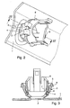
- Fig. 2
- das Anbauteil mit der Aufnahme nach Fig. 1 mit einem in diese Aufnahme eingesteckten, über eine Schnappverbindung allseits lagefixierten Aufsteckelement,
- Fig. 3
- einen Schnitt durch die Einrichtung nach Fig. 2 längs der in Fig. 1 angegebenen Schnittlinie III-III.
- Als ein Anbauteil 1 dient in dem Ausführungsbeispiel ein aus Kunststoff bestehender Außenbereich eines Stoßfängers eines Kraftfahrzeuges. Der Kunststoff ist materialmäßig nicht geeignet, um aus ihm ein elastisch verformbares Schnappverschlußelement ausbilden zu können. Die Befestigungseinrichtung befindet sich bei dem Anbauteil 1 an einer Öffnung 2, in die ein nicht gezeichneter Parksensor als zu befestigendes Teil einführbar ist.
- Auf der von der Sichtseite des als Stoßfänger dienenden Anbauteils 1 abgewandten Innenfläche des Stoßfängers ist in einem allseits etwa konkav verlaufenden Flächenbereich um die Öffnung 2 herum eine Aufnahme angeformt. Diese Aufnahme besteht aus zwei diametral gegenüberliegenden Stegen 3. Jeder dieser beiden Stege 3 verläuft auf der Mantelfläche eines in die Öffnung 2 einlaufenden Konus, wobei der Konusdurchmesser in Richtung auf die Öffnung 2 abnimmt. Die Stege 3 verlaufen damit gegenüber der Ebene der Öffnung 2 in einem stumpfen Winkel von dieser Öffnung aus gesehen.
- Im Fußbereich jedes der beiden Stege 3 ist ein Durchbruch 4 vorgesehen, der die Form eines länglichen Rechtecks aufweist. An den freien Enden weisen die Stege 3 jeweils in ihrer Umfangsmitte in Längsrichtung fingerartig herausragende Abschnitte 5 auf.
- Bei der Darstellung nach Fig. 2 ist ein Aufsteckelement 6 zwischen den Stegen 3 über eine Schnappverbindung gehaltert. Die Schnappverbindung wird erzeugt über zwei an dem Aufsteckelement 6 vorgesehene, nach radial außen federnd ausgebildete Zungen 7, die über an deren Enden vorgesehene radial abragende Widerhaken 8 in die Durchbrüche 4 der Stege 3 nach außen federnd eingreifen. Das Aufsteckelement 6 nimmt den Parksensor als zu befestigendes Teil über ebenfalls einen Schnappverschluß auf.
- Um eine allseits stabile Verbindung zwischen den Stegen 3 und dem Aufsteckelement 6 sicherzustellen, sind an dem Aufsteckelement Taschen 9 vorgesehen, in die die freien Enden der Stege 3 mit ihren seitlich an den jeweiligen fingerartigen Abschnitt 5 angrenzenden Bereichen allseits lagefixierend eingreifen. Gebildet werden diese Taschen 9 jeweils von einem Paar L-förmiger, an das Aufsteckelement 6 angeformter Winkel-Stege. Durch die Mittel-Abschnitte 5 an den Stegen 3 ist eine Fixierung zwischen dem Aufsteckelement 6 und den Stegen 3 in Umfangsrichtung gegeben. Die axiale Fixierung zwischen dem Aufsteckelement 6 und den Stegen 3 der Aufnahme erfolgt an einem axialen Ende durch den jeweiligen Widerhaken 8 an den Zungen 7 des Aufsteckelementes 6 und einer zugeordneten Anlagefläche sowie an dem anderen Ende innerhalb der Taschen 9.
- Bei der Darstellung in Fig. 2 ragen die Stege 3 in Längsrichtung des als Außenbereich eines Stoßfängers dienenden Anbauteils 1 ab. Die umfangsmäßigen Freiräume zwischen den beiden Stegen 3 erstrecken sich dagegen in Querrichtung. Die insbesondere aus Fig. 2 ersichtliche Anordnung und Ausbildung der die Öffnung 2 umgebenden Aufnahme mit den beiden umfangsmäßig voneinander getrennten Stegen 3 eignet sich ausgezeichnet für eine Herstellung des aus Kunststoff bestehenden Stoßfänger-Außenbereiches mittels einfach teilbarer Formwerkzeuge.
Claims (2)
- Befestigungseinrichtung an einem Kunststoff-Anbauteil für ein Kraftfahrzeug, insbesondere an einem Stoßfänger, mit einer an dem Anbauteil einstückig angeformten Aufnahme für ein an dem Anbauteil mittels einer Schnappverbindung zu befestigendes Teil, das ebenso wie die Aufnahme kein elastisch verformbares Schnappverbindungselement besitzt und einem Aufsteckelement mit elastisch verformbaren Schnappverbindungselementen für lagefixierende Schnappverbindungen mit einerseits dem zu befestigenden Teil und andererseits der Aufnahme an dem Anbauteil, wobei das Aufsteckelement in die Aufnahme einschiebbar ausgebildet ist,
gekennzeichnet durch die Merkmale,- die Aufnahme des Anbauteils (1) besitzt für den Eingriff mindestens einer der Schnappverbindungsmittel des Aufsteckelementes (6) im wesentlich gegenüberliegende, umfangsmäßig begrenzte Stege (3) mit mindestens jeweils einem Hinterschnitt (4) mit Bezug auf die Einschieberichtung des Aufsteckelementes (6) zur Erzielung der betreffenden Schnappverbindung,- das Aufsteckelement (6) ist mit Taschen (9) für den Eingriff der Stege (3) der Aufnahme des Anbauteils (1) versehen, in denen die Stege (3) mit jeweils frei auslaufenden Endbereichen in einer senkrecht zur Einschieberichtung des Aufsteckelementes (6) verlaufenden Ebene allseits lagefixiert sind. - Befestigungseinrichtung nach Anspruch 1,
dadurch gekennzeichnet,
daß das Aufsteckelement (6) in der Aufnahme des Anbauteils (1) axial fixiert ist durch Anliegen der Stege (3) innerhalb der Taschen (9) des Aufsteckelementes (6) und der als Zungen (7) ausgebildeten Schnappverbindungsmittel des Aufsteckelementes (6) an den als Durchbrüchen (4) ausgebildeten Hinterschnitten der Stege (3).
Applications Claiming Priority (2)
| Application Number | Priority Date | Filing Date | Title |
|---|---|---|---|
| DE10210129 | 2002-03-08 | ||
| DE10210129A DE10210129C1 (de) | 2002-03-08 | 2002-03-08 | Befestigungseinrichtung an einem Kunststoff-Anbauteil für Kraftfahrzeuge |
Publications (3)
| Publication Number | Publication Date |
|---|---|
| EP1342626A2 true EP1342626A2 (de) | 2003-09-10 |
| EP1342626A3 EP1342626A3 (de) | 2004-05-19 |
| EP1342626B1 EP1342626B1 (de) | 2007-11-07 |
Family
ID=27740688
Family Applications (1)
| Application Number | Title | Priority Date | Filing Date |
|---|---|---|---|
| EP03004760A Expired - Lifetime EP1342626B1 (de) | 2002-03-08 | 2003-03-05 | Befestigungseinrichtung an einem Kunststoff-Anbauteil für Kraftfahrzeuge |
Country Status (4)
| Country | Link |
|---|---|
| US (1) | US6839943B2 (de) |
| EP (1) | EP1342626B1 (de) |
| DE (1) | DE10210129C1 (de) |
| ES (1) | ES2297063T3 (de) |
Cited By (3)
| Publication number | Priority date | Publication date | Assignee | Title |
|---|---|---|---|---|
| FR2928114A1 (fr) * | 2008-03-03 | 2009-09-04 | Plastic Omnium Cie | Support pour capteur destine a etre place sur un vehicule automobile |
| EP1702733A3 (de) * | 2005-03-18 | 2011-10-05 | Faurecia Exteriors GmbH | Prägestanzen von Kunststoffen mit höchster Genauigkeit |
| EP3144187A1 (de) * | 2015-09-16 | 2017-03-22 | SMP Deutschland GmbH | Vekleidungsbauteil für ein fahrzeug und verfahren zum befestigen und ausrichten eines sensors und/oder einer sensoraufnahme an einem verkleidungsbauteil eines fahrzeugs sowie ein fahrzeug mit einem derartigen verkleidungsbauteil |
Families Citing this family (8)
| Publication number | Priority date | Publication date | Assignee | Title |
|---|---|---|---|---|
| CA2550288C (en) * | 2003-09-04 | 2013-02-05 | William D. Blake | Fascia for motor vehicle with integral component mounting and a method of making the same |
| DE102004037257A1 (de) * | 2004-07-31 | 2006-02-16 | Robert Bosch Gmbh | Einbauvorrichtung für einen Sensor |
| DE102006032869A1 (de) * | 2006-07-14 | 2008-01-17 | Rehau Ag + Co. | Verbindungsvorrichtung zur Verbindung einer Funktionsaufbaukomponente mit einer Kunststofftragstruktur eines Kraftfahrzeuges |
| DE102007009154A1 (de) * | 2007-02-24 | 2008-08-28 | Dr. Ing. H.C. F. Porsche Aktiengesellschaft | Bauteilhalterung |
| US8702135B2 (en) * | 2012-09-04 | 2014-04-22 | Ford Global Technologies, Llc | Radar compatible automotive badge and fascia |
| US9097270B2 (en) * | 2013-07-26 | 2015-08-04 | GM Global Technology Operations LLC | Snap fit fastener |
| FR3102553B1 (fr) * | 2019-10-28 | 2021-10-22 | Valeo Systemes Dessuyage | Dispositif de détection d’un véhicule automobile comprenant un dispositif de fixation pour un capteur/émetteur. |
| DE202023107513U1 (de) * | 2023-12-19 | 2025-03-20 | REHAU Automotive, s.r.o. | Außenverkleidungsteil für ein Fahrzeug |
Citations (1)
| Publication number | Priority date | Publication date | Assignee | Title |
|---|---|---|---|---|
| DE19819698A1 (de) | 1998-05-02 | 1999-11-11 | Daimler Chrysler Ag | Befestigungseinrichtung an einem Anbauteil für ein Kraftfahrzeug |
Family Cites Families (13)
| Publication number | Priority date | Publication date | Assignee | Title |
|---|---|---|---|---|
| US4620736A (en) * | 1984-08-20 | 1986-11-04 | Franklin L. Best | Adaptor plate for vehicle bumper |
| US4875728A (en) * | 1988-09-16 | 1989-10-24 | Chrysler Motors Corporation | Bumper facia attachment structure |
| US5269640A (en) * | 1991-06-03 | 1993-12-14 | Aoyama Seisakusho Co., Ltd. | Holding device for use in assembling mechanical members |
| DE4326661A1 (de) * | 1993-08-09 | 1995-02-16 | Happich Gmbh Gebr | Gegenlagerböckchen für Fahrzeugsonnenblenden |
| DE19621964B4 (de) * | 1996-05-31 | 2005-02-24 | Daimlerchrysler Ag | Vorrichtung zur ortsvariablen Befestigung eines Halters an einem Aufnahmeteil |
| DE19823761A1 (de) * | 1997-07-11 | 1999-01-14 | Bosch Gmbh Robert | Befestigungselement für einen Körper in einer Wandung |
| EP1005692B2 (de) * | 1997-08-21 | 2006-12-27 | Valeo Schalter und Sensoren GmbH | Mit dem stossfänger eines kraftfahrzeugs verbundene aufnahmehülse für sensoren |
| FR2792899B1 (fr) * | 1999-04-30 | 2001-06-15 | Plastic Omnium Cie | Dispositif de fixation d'un capteur de positionnement et piece de carrosserie munie d'un tel dispositif |
| US6113164A (en) * | 1999-05-20 | 2000-09-05 | Setina Manufacturing Company | Auxiliary push bumper for motor vehicle |
| DE19939746C2 (de) * | 1999-08-21 | 2001-12-06 | Valeo Schalter & Sensoren Gmbh | Befestigungseinrichtung zur Befestigung von Ultraschallwandlern an Fahrzeugen |
| DE19943293C2 (de) * | 1999-09-10 | 2002-02-14 | Porsche Ag | Halteeinrichtung für einen Ultraschallwandler an einem Aussenteil eines Kraftfahrzeuges |
| FR2809691B1 (fr) * | 2000-05-31 | 2002-08-30 | Ecia Equip Composants Ind Auto | Element de protection d'un vehicule automobile |
| US6364589B1 (en) * | 2001-02-16 | 2002-04-02 | Magna Interior Systems, Inc. | Panel fastener assembly |
-
2002
- 2002-03-08 DE DE10210129A patent/DE10210129C1/de not_active Expired - Fee Related
-
2003
- 2003-02-26 US US10/374,701 patent/US6839943B2/en not_active Expired - Lifetime
- 2003-03-05 EP EP03004760A patent/EP1342626B1/de not_active Expired - Lifetime
- 2003-03-05 ES ES03004760T patent/ES2297063T3/es not_active Expired - Lifetime
Patent Citations (1)
| Publication number | Priority date | Publication date | Assignee | Title |
|---|---|---|---|---|
| DE19819698A1 (de) | 1998-05-02 | 1999-11-11 | Daimler Chrysler Ag | Befestigungseinrichtung an einem Anbauteil für ein Kraftfahrzeug |
Cited By (4)
| Publication number | Priority date | Publication date | Assignee | Title |
|---|---|---|---|---|
| EP1702733A3 (de) * | 2005-03-18 | 2011-10-05 | Faurecia Exteriors GmbH | Prägestanzen von Kunststoffen mit höchster Genauigkeit |
| FR2928114A1 (fr) * | 2008-03-03 | 2009-09-04 | Plastic Omnium Cie | Support pour capteur destine a etre place sur un vehicule automobile |
| EP2098415A1 (de) * | 2008-03-03 | 2009-09-09 | Compagnie Plastic Omnium | Sensorträger für Kraftfahrzeuge |
| EP3144187A1 (de) * | 2015-09-16 | 2017-03-22 | SMP Deutschland GmbH | Vekleidungsbauteil für ein fahrzeug und verfahren zum befestigen und ausrichten eines sensors und/oder einer sensoraufnahme an einem verkleidungsbauteil eines fahrzeugs sowie ein fahrzeug mit einem derartigen verkleidungsbauteil |
Also Published As
| Publication number | Publication date |
|---|---|
| EP1342626B1 (de) | 2007-11-07 |
| US20040098844A1 (en) | 2004-05-27 |
| ES2297063T3 (es) | 2008-05-01 |
| DE10210129C1 (de) | 2003-11-06 |
| EP1342626A3 (de) | 2004-05-19 |
| US6839943B2 (en) | 2005-01-11 |
Similar Documents
| Publication | Publication Date | Title |
|---|---|---|
| EP0239984B1 (de) | Befestigungs-Anordnung für ein Ende eines Bowden-Seilzuges, insbesondere für Seilzug-Betätigungen in Kraftfahrzeugen | |
| EP3077684B1 (de) | Ringförmige steckkupplung sowie ein herstellungs- und ein verbindungsverfahren dafür | |
| DE102004030666B4 (de) | Gehäuse zur Aufnahme elektrischer und/oder elektronischer Bauteile | |
| DE202005011420U1 (de) | Steckkupplung mit dreidimensionaler Ausgleichsbewegung in Plattenmontage | |
| DE10210129C1 (de) | Befestigungseinrichtung an einem Kunststoff-Anbauteil für Kraftfahrzeuge | |
| WO2008031655A1 (de) | Befestigungseinrichtung für eine leitung | |
| DE3007702A1 (de) | Inspektionskammer fuer eine drainageanlage | |
| WO1983004067A1 (fr) | Dispositif pour joindre des pieces avec un jeu angulaire | |
| WO1999032796A1 (de) | Kugelschale für ein kugelgelenk und kugelgelenk mit einer solchen kugelschale | |
| DE10355363B4 (de) | Lageranordnung | |
| DE20201573U1 (de) | Aufnahmeteil einer Fluid-Steckkupplung | |
| DE102017207012A1 (de) | Lager für eine Lenkspindel und Lenksäule für ein Kraftfahrzeug | |
| DE19725642A1 (de) | Verfahren zur Herstellung eines Verbundes aus zwei Kunststoffteilen | |
| EP1718507A1 (de) | Scheibenwischanlage für fahrzeuge sowie befestigungselement für eine solche anlage | |
| DE9306761U1 (de) | Anschlußteil für einen Betätigungszug | |
| DE102010053082A1 (de) | Fluidarmatur | |
| DE3808284C2 (de) | ||
| DE202024105653U1 (de) | Befestigungselement zur reversiblen Verbindung mit einem Haltemittel | |
| EP1083073A2 (de) | Endseitige Haltevorrichtung für eine Entlüftungsleitung eines Aktivkohlefilters | |
| DE19612424B4 (de) | Schalthebelvorrichtung | |
| DE102007003319A1 (de) | Befestigungsclip und Bauteilverbindung mit einem Befestigungsclip | |
| DE102023125438A1 (de) | Kupplungsbuchse mit leichtgängiger Dichtung | |
| DE102005040850A1 (de) | Haltevorrichtung zur Befestigung eines schlauchartigen Elementes auf einem rohrartigen Körper und Verfahren dazu | |
| DE102017223636A1 (de) | Montageeinheit sowie Fixierhülse für eine solche Montageeinheit | |
| DE19820544A1 (de) | Behälterdeckeleinrichtung sowie Verfahren zur Herstellung einer Deckelhalterung hierfür |
Legal Events
| Date | Code | Title | Description |
|---|---|---|---|
| PUAI | Public reference made under article 153(3) epc to a published international application that has entered the european phase |
Free format text: ORIGINAL CODE: 0009012 |
|
| AK | Designated contracting states |
Kind code of ref document: A2 Designated state(s): AT BE BG CH CY CZ DE DK EE ES FI FR GB GR HU IE IT LI LU MC NL PT RO SE SI SK TR |
|
| AX | Request for extension of the european patent |
Extension state: AL LT LV MK |
|
| PUAL | Search report despatched |
Free format text: ORIGINAL CODE: 0009013 |
|
| AK | Designated contracting states |
Kind code of ref document: A3 Designated state(s): AT BE BG CH CY CZ DE DK EE ES FI FR GB GR HU IE IT LI LU MC NL PT RO SE SI SK TR |
|
| AX | Request for extension of the european patent |
Extension state: AL LT LV MK |
|
| 17P | Request for examination filed |
Effective date: 20041119 |
|
| AKX | Designation fees paid |
Designated state(s): ES FR GB IT |
|
| REG | Reference to a national code |
Ref country code: DE Ref legal event code: 8566 |
|
| RAP1 | Party data changed (applicant data changed or rights of an application transferred) |
Owner name: PLASTAL GMBH |
|
| RAP1 | Party data changed (applicant data changed or rights of an application transferred) |
Owner name: PLASTAL GMBH |
|
| GRAP | Despatch of communication of intention to grant a patent |
Free format text: ORIGINAL CODE: EPIDOSNIGR1 |
|
| GRAS | Grant fee paid |
Free format text: ORIGINAL CODE: EPIDOSNIGR3 |
|
| GRAA | (expected) grant |
Free format text: ORIGINAL CODE: 0009210 |
|
| AK | Designated contracting states |
Kind code of ref document: B1 Designated state(s): ES FR GB IT |
|
| REG | Reference to a national code |
Ref country code: GB Ref legal event code: FG4D Free format text: NOT ENGLISH |
|
| GBT | Gb: translation of ep patent filed (gb section 77(6)(a)/1977) |
Effective date: 20080212 |
|
| REG | Reference to a national code |
Ref country code: ES Ref legal event code: FG2A Ref document number: 2297063 Country of ref document: ES Kind code of ref document: T3 |
|
| ET | Fr: translation filed | ||
| PLBE | No opposition filed within time limit |
Free format text: ORIGINAL CODE: 0009261 |
|
| STAA | Information on the status of an ep patent application or granted ep patent |
Free format text: STATUS: NO OPPOSITION FILED WITHIN TIME LIMIT |
|
| 26N | No opposition filed |
Effective date: 20080808 |
|
| REG | Reference to a national code |
Ref country code: GB Ref legal event code: 732E Free format text: REGISTERED BETWEEN 20150521 AND 20150527 |
|
| REG | Reference to a national code |
Ref country code: FR Ref legal event code: PLFP Year of fee payment: 14 |
|
| REG | Reference to a national code |
Ref country code: FR Ref legal event code: PLFP Year of fee payment: 15 |
|
| REG | Reference to a national code |
Ref country code: FR Ref legal event code: PLFP Year of fee payment: 16 |
|
| PGFP | Annual fee paid to national office [announced via postgrant information from national office to epo] |
Ref country code: IT Payment date: 20200218 Year of fee payment: 18 Ref country code: GB Payment date: 20200221 Year of fee payment: 18 |
|
| PGFP | Annual fee paid to national office [announced via postgrant information from national office to epo] |
Ref country code: FR Payment date: 20200220 Year of fee payment: 18 |
|
| PGFP | Annual fee paid to national office [announced via postgrant information from national office to epo] |
Ref country code: ES Payment date: 20200401 Year of fee payment: 18 |
|
| GBPC | Gb: european patent ceased through non-payment of renewal fee |
Effective date: 20210305 |
|
| PG25 | Lapsed in a contracting state [announced via postgrant information from national office to epo] |
Ref country code: GB Free format text: LAPSE BECAUSE OF NON-PAYMENT OF DUE FEES Effective date: 20210305 Ref country code: FR Free format text: LAPSE BECAUSE OF NON-PAYMENT OF DUE FEES Effective date: 20210331 |
|
| PG25 | Lapsed in a contracting state [announced via postgrant information from national office to epo] |
Ref country code: IT Free format text: LAPSE BECAUSE OF NON-PAYMENT OF DUE FEES Effective date: 20210305 |
|
| REG | Reference to a national code |
Ref country code: ES Ref legal event code: FD2A Effective date: 20220517 |
|
| PG25 | Lapsed in a contracting state [announced via postgrant information from national office to epo] |
Ref country code: ES Free format text: LAPSE BECAUSE OF NON-PAYMENT OF DUE FEES Effective date: 20210306 |