EP1342556B1 - Verfahren zur Herstellung eines Bauteiles in Faserverbundbauweise - Google Patents
Verfahren zur Herstellung eines Bauteiles in Faserverbundbauweise Download PDFInfo
- Publication number
- EP1342556B1 EP1342556B1 EP03002879A EP03002879A EP1342556B1 EP 1342556 B1 EP1342556 B1 EP 1342556B1 EP 03002879 A EP03002879 A EP 03002879A EP 03002879 A EP03002879 A EP 03002879A EP 1342556 B1 EP1342556 B1 EP 1342556B1
- Authority
- EP
- European Patent Office
- Prior art keywords
- preform
- component
- braiding
- core
- braided
- Prior art date
- Legal status (The legal status is an assumption and is not a legal conclusion. Google has not performed a legal analysis and makes no representation as to the accuracy of the status listed.)
- Expired - Lifetime
Links
- 238000000034 method Methods 0.000 title claims description 27
- 239000003733 fiber-reinforced composite Substances 0.000 title 1
- 239000000835 fiber Substances 0.000 claims abstract description 13
- 239000011347 resin Substances 0.000 claims abstract description 11
- 229920005989 resin Polymers 0.000 claims abstract description 11
- 238000009954 braiding Methods 0.000 claims description 17
- 238000009745 resin transfer moulding Methods 0.000 claims description 9
- 239000002131 composite material Substances 0.000 claims description 7
- 239000000463 material Substances 0.000 claims description 6
- 230000003014 reinforcing effect Effects 0.000 claims description 5
- 238000005553 drilling Methods 0.000 claims description 3
- 238000003801 milling Methods 0.000 claims description 3
- 239000000203 mixture Substances 0.000 claims description 2
- 239000003795 chemical substances by application Substances 0.000 claims 1
- 238000010348 incorporation Methods 0.000 claims 1
- 238000003754 machining Methods 0.000 claims 1
- 239000002657 fibrous material Substances 0.000 abstract description 13
- 238000001721 transfer moulding Methods 0.000 abstract description 2
- 229920002430 Fibre-reinforced plastic Polymers 0.000 abstract 2
- 239000011151 fibre-reinforced plastic Substances 0.000 abstract 2
- 239000011265 semifinished product Substances 0.000 description 10
- 238000004519 manufacturing process Methods 0.000 description 5
- 238000010276 construction Methods 0.000 description 4
- 230000002787 reinforcement Effects 0.000 description 3
- 239000004744 fabric Substances 0.000 description 2
- 235000003332 Ilex aquifolium Nutrition 0.000 description 1
- 241000209027 Ilex aquifolium Species 0.000 description 1
- 230000006978 adaptation Effects 0.000 description 1
- XAGFODPZIPBFFR-UHFFFAOYSA-N aluminium Chemical compound [Al] XAGFODPZIPBFFR-UHFFFAOYSA-N 0.000 description 1
- 229910052782 aluminium Inorganic materials 0.000 description 1
- 238000003780 insertion Methods 0.000 description 1
- 230000037431 insertion Effects 0.000 description 1
- 238000009434 installation Methods 0.000 description 1
- 238000012423 maintenance Methods 0.000 description 1
- 238000000465 moulding Methods 0.000 description 1
- 239000004848 polyfunctional curative Substances 0.000 description 1
- 238000012545 processing Methods 0.000 description 1
- 238000009958 sewing Methods 0.000 description 1
Images
Classifications
-
- B—PERFORMING OPERATIONS; TRANSPORTING
- B29—WORKING OF PLASTICS; WORKING OF SUBSTANCES IN A PLASTIC STATE IN GENERAL
- B29D—PRODUCING PARTICULAR ARTICLES FROM PLASTICS OR FROM SUBSTANCES IN A PLASTIC STATE
- B29D99/00—Subject matter not provided for in other groups of this subclass
- B29D99/0003—Producing profiled members, e.g. beams
- B29D99/0007—Producing profiled members, e.g. beams having a variable cross-section
-
- B—PERFORMING OPERATIONS; TRANSPORTING
- B29—WORKING OF PLASTICS; WORKING OF SUBSTANCES IN A PLASTIC STATE IN GENERAL
- B29C—SHAPING OR JOINING OF PLASTICS; SHAPING OF MATERIAL IN A PLASTIC STATE, NOT OTHERWISE PROVIDED FOR; AFTER-TREATMENT OF THE SHAPED PRODUCTS, e.g. REPAIRING
- B29C70/00—Shaping composites, i.e. plastics material comprising reinforcements, fillers or preformed parts, e.g. inserts
- B29C70/04—Shaping composites, i.e. plastics material comprising reinforcements, fillers or preformed parts, e.g. inserts comprising reinforcements only, e.g. self-reinforcing plastics
- B29C70/28—Shaping operations therefor
- B29C70/30—Shaping by lay-up, i.e. applying fibres, tape or broadsheet on a mould, former or core; Shaping by spray-up, i.e. spraying of fibres on a mould, former or core
- B29C70/34—Shaping by lay-up, i.e. applying fibres, tape or broadsheet on a mould, former or core; Shaping by spray-up, i.e. spraying of fibres on a mould, former or core and shaping or impregnating by compression, i.e. combined with compressing after the lay-up operation
- B29C70/347—Shaping by lay-up, i.e. applying fibres, tape or broadsheet on a mould, former or core; Shaping by spray-up, i.e. spraying of fibres on a mould, former or core and shaping or impregnating by compression, i.e. combined with compressing after the lay-up operation combined with compressing after the winding of lay-ups having a non-circular cross-section, e.g. flat spiral windings
-
- B—PERFORMING OPERATIONS; TRANSPORTING
- B29—WORKING OF PLASTICS; WORKING OF SUBSTANCES IN A PLASTIC STATE IN GENERAL
- B29C—SHAPING OR JOINING OF PLASTICS; SHAPING OF MATERIAL IN A PLASTIC STATE, NOT OTHERWISE PROVIDED FOR; AFTER-TREATMENT OF THE SHAPED PRODUCTS, e.g. REPAIRING
- B29C70/00—Shaping composites, i.e. plastics material comprising reinforcements, fillers or preformed parts, e.g. inserts
- B29C70/04—Shaping composites, i.e. plastics material comprising reinforcements, fillers or preformed parts, e.g. inserts comprising reinforcements only, e.g. self-reinforcing plastics
- B29C70/28—Shaping operations therefor
- B29C70/40—Shaping or impregnating by compression not applied
- B29C70/42—Shaping or impregnating by compression not applied for producing articles of definite length, i.e. discrete articles
- B29C70/46—Shaping or impregnating by compression not applied for producing articles of definite length, i.e. discrete articles using matched moulds, e.g. for deforming sheet moulding compounds [SMC] or prepregs
- B29C70/48—Shaping or impregnating by compression not applied for producing articles of definite length, i.e. discrete articles using matched moulds, e.g. for deforming sheet moulding compounds [SMC] or prepregs and impregnating the reinforcements in the closed mould, e.g. resin transfer moulding [RTM], e.g. by vacuum
-
- B—PERFORMING OPERATIONS; TRANSPORTING
- B64—AIRCRAFT; AVIATION; COSMONAUTICS
- B64C—AEROPLANES; HELICOPTERS
- B64C9/00—Adjustable control surfaces or members, e.g. rudders
- B64C9/02—Mounting or supporting thereof
-
- Y—GENERAL TAGGING OF NEW TECHNOLOGICAL DEVELOPMENTS; GENERAL TAGGING OF CROSS-SECTIONAL TECHNOLOGIES SPANNING OVER SEVERAL SECTIONS OF THE IPC; TECHNICAL SUBJECTS COVERED BY FORMER USPC CROSS-REFERENCE ART COLLECTIONS [XRACs] AND DIGESTS
- Y02—TECHNOLOGIES OR APPLICATIONS FOR MITIGATION OR ADAPTATION AGAINST CLIMATE CHANGE
- Y02T—CLIMATE CHANGE MITIGATION TECHNOLOGIES RELATED TO TRANSPORTATION
- Y02T50/00—Aeronautics or air transport
- Y02T50/40—Weight reduction
-
- Y—GENERAL TAGGING OF NEW TECHNOLOGICAL DEVELOPMENTS; GENERAL TAGGING OF CROSS-SECTIONAL TECHNOLOGIES SPANNING OVER SEVERAL SECTIONS OF THE IPC; TECHNICAL SUBJECTS COVERED BY FORMER USPC CROSS-REFERENCE ART COLLECTIONS [XRACs] AND DIGESTS
- Y10—TECHNICAL SUBJECTS COVERED BY FORMER USPC
- Y10T—TECHNICAL SUBJECTS COVERED BY FORMER US CLASSIFICATION
- Y10T156/00—Adhesive bonding and miscellaneous chemical manufacture
- Y10T156/10—Methods of surface bonding and/or assembly therefor
- Y10T156/1002—Methods of surface bonding and/or assembly therefor with permanent bending or reshaping or surface deformation of self sustaining lamina
- Y10T156/1005—Methods of surface bonding and/or assembly therefor with permanent bending or reshaping or surface deformation of self sustaining lamina by inward collapsing of portion of hollow body
Definitions
- the invention relates to a method for producing a Component in fiber composite construction of a fitting for aircraft structures using an RTM process resin transfer molding, in which a prefabricated Semi-finished products made of fiber materials in a closed Inserted into the mold, a vacuum is created in the mold, the semi-finished product impregnated with resin or with a resin / hardener mixture and then cured under pressure and temperature becomes.
- US-A-5 624 618 is a method for producing a Structure for an aircraft gas turbine has become known. in this connection becomes a method of forming a braided composite construction of complex geometry with cavities proposed, the cavities of walls with shaped Areas are limited. There are a variety of mesh-shaped removable mold cores with molds for adaptation to the desired cavity geometry. Furthermore form the cores along a horizontal axis into an arrangement stacked and braiding fibers over the stacked Arrangement of mold cores carried out.
- Cutting is carried out to separate the braided mold cores at the cavity ends and it closes a side Stack the separate mandrels that the cavity ends lying side by side and molding the side includes stacked braided mandrels.
- the invention is based on the object, an automated Process for the production of semi-finished products or components to create the type mentioned.
- the main advantages of the method according to the invention are in a short process time, high reproducibility and high output rate as well as a lower weight Components made of aluminum and with less maintenance to see at the airlines.
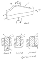
- the near-net shape tool core 1 consists of two composite tool core halves, namely the a curvature 2a braided core top 2 and the cuboid braided core lower part 3.
- the one from the halves 2 and 3 composite tool core 1 is in a first Process step for the production of a component in fiber composite construction, preferably a fitting for aircraft structures, with the help of an automatic circular braiding process braided with at least one layer of fiber material.
- the direction of braiding is indicated by an arrow 4.
- the first section I in FIG. 2 shows a tool core 1 with its two halves 2 and 3, the tool core 1 of several layers of fiber material 5 is braided.
- the tool core 1 of several layers of fiber material 5 is braided.
- the boarding All layers of fiber material are made using the above automatic circular braiding process.
- the second section II in Fig. 2 shows an incomplete Tool core 1, since the cuboid lower part 3 after the completion of the braid 6 has been removed.
- the braid 6 is pressed into the specified shape brought the semi-finished product 7, wherein section II an intermediate position shows.
- the final shape of the semi-finished product 7 is Section III can be seen, the shaped semifinished product 7 Rail connections 8 has.
- Under a spar connector 8 is a connection to the primary structure of an aircraft understand. It is also possible to remove the braid after it has been removed the cuboid braided core lower part 3 and in front the insertion in the RTM device by changing the reinforcement layers in a skin connections 15 having semifinished product to reform, as can be seen, for example, from FIG. 3 is.
- a skin connection 15 through the outer skin of a structural component are formed.
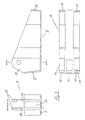
- the fitting 9 shown in FIG. 3 for an aircraft structure can be produced by the method according to the invention, being a system for performing the circular braiding process Application.
- the system consists of a circular braiding machine, a manipulation system and an industrial robot, that has a complex braided core. in this connection can preliminary profile shapes by forming and sewing, Node elements with a demountable core and hollow body with a meltable one Core are generated.
- the fitting 9 has a double-T cross-section 10, wherein between each other via a crossbar 11 connected webs 12 and 13 is a blind area 14.
- the fitting 9 is made of braided layers 5, i.e. from layers of fiber material built up, with the selected material thicknesses can be chosen so that the braiding one Thickness of 1.2 mm for a braided layer and a thickness of 0.25 mm for a reinforcement layer with approximately 60% fiber volume results.
- the thickness of the Braided layer of 0.4 mm thickness for the standing thread layers and 0.8 mm thickness for the layers of braiding in + and - orientation.
- the fitting 9 produced in the round braiding process has process-specific properties, for example the braided hose over the crosspiece area 10 of the fitting 9 a variable fiber course.
- this course will start at +/- 30 ° and at +/- 60 ° to 70 'ends.
- the standing threads also have over the braiding area (0 °) a variable angle.
Landscapes
- Engineering & Computer Science (AREA)
- Mechanical Engineering (AREA)
- Chemical & Material Sciences (AREA)
- Composite Materials (AREA)
- Aviation & Aerospace Engineering (AREA)
- Moulding By Coating Moulds (AREA)
- Casting Or Compression Moulding Of Plastics Or The Like (AREA)
- Multicomponent Fibers (AREA)
- Woven Fabrics (AREA)
Description
- ein endkonturennaher, aus zwei trennbaren Hälften bestehender Werkzeugkern wird mittels eines automatischen Rundflechtprozesses mit mindestens einer Lage aus Faserwerkstoff umflochten,
- nach Fertigstellung des Geflechtes wird eine Hälfte des Werkzeugkernes entfernt,
- das die andere Werkzeugkernhälfte umgebende Geflecht wird in die vorgegebene Form des Halbzeuges gepreßt,
- das ausgeformte Halbzeug wird in eine RTM-Vorrichtung eingelegt, mit Harz imprägniert und zur Fertigstellung des Bauteiles ausgehärtet, und
- die in dem Bauteil verbliebene Hälfte des Werkzeugkernes wird aus dem Bauteil entfernt.
- Fig. 1
- den Werkzeugkern in perspektivischer Ansicht, sowie
- Fig. 2
- drei Seitenansichten des Werkzeugkernes gemäß Fig. 1 im Schnitt A-A, wobei der Werkzeugkern von mehreren Lagen aus Faserwerkstoff umwickelt ist.
- Fig. 3
- zeigt weiterhin einen nach dem erfindungsgemäßen Verfahren hergestellten Beschlag in Vorder-, Seiten- und Draufsicht.
- 1
- endkonturennaher Werkzeugkern
- 2
- Flechtkernoberteil / obere Hälfte des Werkzeugkerns 1
- 2a
- Wölbung des Flechtkernoberteil 2
- 3
- Flechtkernunterteil / untere Hälfte des Werkzeugkerns 1
- 4
- Richtungpfeil für Flechtrichtung
- 5
- Lagen aus Faserwerkstoff
- 6
- Geflecht aus Faserwerkstoff 5
- 7
- Halbzeug
- 8
- Holmanschlüsse
- 9
- Beschlag
- 10
- Doppel-T-Querschnitt des Beschlages 9
- 11
- Quersteg des Beschlages 9
- 12
- Steg des Beschlages 9
- 13
- Steg des Beschlages 9
- 14
- Blindbereich Beschlages 9
- 15
- Hautanschluß
Claims (6)
- Verfahren zur Herstellung eines Bauteiles in Faserverbundbauweise als Beschlages für Flugzeugstrukturen unter Anwendung eines RTM-Verfahrens-resin transfer molding-, bei dem ein vorgefertigtes Halbzeug aus Faserwerkstoffen in eine geschlossene Form eingelegt, in der Form ein Vakuum erzeugt, das Halbzeug mit Harz bzw. mit einem Harz/Härter-Gemisch getränkt und anschließend unter Druck und Temperatur ausgehärtet wird, wobeiein endkonturennaher, aus zwei trennbaren Hälften (2, 3) bestehender Werkzeugkern (1) wird mittels eines automatischen Rundflechtprozesses mit mindestens einer Lage aus Faserwerkstoff (5) umflochten,nach Fertigstellung des Geflechtes (6) wird eine Hälfte (3) des Werkzeugkernes (1) entfernt,das die andere Werkzeugkernhälfte (2) umgebende Geflecht (6) wird in die vorgegebene Form des Halbzeuges (7) gepreßt,das ausgeformte Halbzeug (7) wird in eine RTM-Vorrichtung eingelegt, mit Harz imprägniert und zur Fertigstellung des Bauteiles ausgehärtet, unddie in dem Bauteil verbliebene Hälfte (2) des Werkzeugkernes (1) wird aus dem Bauteil entfernt.
- Verfahren nach Anspruch 1, wobei vorkonfektionierte Verstärkungslagen nach Aufbringung von einer wählbaren Anzahl von Faserwerkstofflagen auf dem Flechtkern fixiert werden, und wobei die Verstärkungslagen mit weiteren Faserwerkstoffen umflochten werden.
- Verfahren nach Anspruch 2, wobei Verstärkungslagen aus Faserwerkstoffen (5) verwendet werden.
- Verfahren nach Anspruch 1, 2 oder 3, wobei das Geflecht (6) nach dem Entfernen der ersten Hälfte (3) des Werkzeugkernes (1) und vor dem Einlegen in die RTM-Vorrichtung in ein Holmanschlüsse (8) aufweisendes Halbzeug (7) umgeformt wird.
- Verfahren nach Anspruch 2 oder 3, wobei das Geflecht (6) nach dem Entfernen der ersten Hälfte (3) des Werkzeugkernes (1) und vor dem Einlegen in die RTM-Vorrichtung durch Umlegen der Verstärkungslagen in ein Hautanschlüsse (15) aufweisendes Halbzeug (7) umgeformt wird.
- Verfahren nach einem der Ansprüche 1 bis 5, wobei das ausgehärtete Bauteil mechanischen Bearbeitungsvorgängen, wie Fräsen, Bohren, Einbau von Buchsen usw. ,unterzogen wird.
Applications Claiming Priority (2)
| Application Number | Priority Date | Filing Date | Title |
|---|---|---|---|
| DE10210517 | 2002-03-09 | ||
| DE10210517A DE10210517B3 (de) | 2002-03-09 | 2002-03-09 | Verfahren zur Herstellung eines Bauteiles in Faserverbundbauweise |
Publications (2)
| Publication Number | Publication Date |
|---|---|
| EP1342556A1 EP1342556A1 (de) | 2003-09-10 |
| EP1342556B1 true EP1342556B1 (de) | 2004-10-20 |
Family
ID=27740732
Family Applications (1)
| Application Number | Title | Priority Date | Filing Date |
|---|---|---|---|
| EP03002879A Expired - Lifetime EP1342556B1 (de) | 2002-03-09 | 2003-02-08 | Verfahren zur Herstellung eines Bauteiles in Faserverbundbauweise |
Country Status (9)
| Country | Link |
|---|---|
| US (1) | US6890470B2 (de) |
| EP (1) | EP1342556B1 (de) |
| JP (1) | JP4235469B2 (de) |
| AT (1) | ATE280033T1 (de) |
| AU (1) | AU2003200918B2 (de) |
| BR (1) | BR0300453B1 (de) |
| CA (1) | CA2421415C (de) |
| DE (2) | DE10210517B3 (de) |
| ES (1) | ES2231738T3 (de) |
Families Citing this family (59)
| Publication number | Priority date | Publication date | Assignee | Title |
|---|---|---|---|---|
| US7752775B2 (en) | 2000-03-10 | 2010-07-13 | Lyden Robert M | Footwear with removable lasting board and cleats |
| EP1342553B1 (de) * | 2002-03-08 | 2016-05-18 | Airbus Operations GmbH | Verfahren zum Herstellen eines Fensterrahmens für Flugzeuge aus faserverstärktem Kunststoff und Vorrichtung zur Durchführung des Verfahrens |
| EP1473131A3 (de) * | 2003-04-30 | 2007-01-03 | Airbus Deutschland GmbH | Verfahren zum herstellen textiler vorformlinge aus textilen halbzeugen |
| DE10322297B4 (de) * | 2003-05-17 | 2007-04-19 | Daimlerchrysler Ag | Verfahren zur Herstellung eines Bauteils aus Faserverbundwerkstoff |
| JP3782072B2 (ja) * | 2003-05-30 | 2006-06-07 | 川崎重工業株式会社 | 複合材型材の成形方法及び装置 |
| DE10347598A1 (de) * | 2003-10-14 | 2005-06-23 | Bayerische Motoren Werke Ag | Bauteil, insbesondere Außenhautbauteil für ein Fahrzeug |
| DE102004028075B4 (de) * | 2004-06-09 | 2015-10-01 | Bayerische Motoren Werke Aktiengesellschaft | Verfahren zur Herstellung eines Faserverbundhalbzeugs |
| FR2900420B1 (fr) * | 2006-04-26 | 2008-07-25 | Snecma Propulsion Solide Sa | Procede de realisation de strate fibreuse pour la fabrication d'une preforme de piece composite |
| US8312646B2 (en) | 2006-05-25 | 2012-11-20 | Nike, Inc. | Article of footwear incorporating a tensile element |
| US7574818B2 (en) * | 2006-05-25 | 2009-08-18 | Nike, Inc. | Article of footwear having an upper with thread structural elements |
| US8893405B2 (en) | 2006-05-25 | 2014-11-25 | Nike, Inc. | Article of footwear incorporating tensile strands with an elongated cross-sectional shape |
| US7546698B2 (en) * | 2006-05-25 | 2009-06-16 | Nike, Inc. | Article of footwear having an upper with thread structural elements |
| US8418380B2 (en) * | 2006-05-25 | 2013-04-16 | Nike, Inc. | Article of footwear having an upper incorporating a tensile strand with a cover layer |
| US8312645B2 (en) * | 2006-05-25 | 2012-11-20 | Nike, Inc. | Material elements incorporating tensile strands |
| US8904671B2 (en) | 2006-05-25 | 2014-12-09 | Nike, Inc. | Footwear incorporating a tensile element with a deposition layer |
| US7870681B2 (en) * | 2006-05-25 | 2011-01-18 | Nike, Inc. | Article of footwear having an upper with thread structural elements |
| GB0712553D0 (en) * | 2007-06-29 | 2007-08-08 | Airbus Uk Ltd | Composite panel stiffener |
| GB0712552D0 (en) * | 2007-06-29 | 2007-08-08 | Airbus Uk Ltd | Elongate composite structural members and improvements therein |
| GB0712549D0 (en) * | 2007-06-29 | 2007-08-08 | Airbus Uk Ltd | Improvements in elongate composite structural members |
| AT505512B1 (de) * | 2007-07-03 | 2009-09-15 | Teufelberger Gmbh | Anordnung zum verbinden eines länglichen elements mit einer weiteren komponente |
| DE102007041431A1 (de) * | 2007-08-29 | 2009-03-05 | Volkswagen Ag | Verfahren zur Herstellung von Bauteilen, insbesondere Resin-Transfer-Molding-Verfahren zum Herstellen von Faserverbundbauteilen |
| DE102008003974B4 (de) | 2008-01-11 | 2013-08-01 | Airbus Operations Gmbh | Verfahren zur Herstellung (teil-)ringförmiger, faserverstärkten Kunststoff enthaltende Bauteile aus FVW-Halbzeugen |
| FR2932409B1 (fr) | 2008-06-13 | 2013-04-12 | Messier Dowty Sa | Procede de fabrication d'une piece structurale en materiau composite a matrice organique, piece obtenue. |
| GB0813161D0 (en) | 2008-07-18 | 2008-08-27 | Airbus Uk Ltd | Ramped stiffener and apparatus and method for forming the same |
| GB0813146D0 (en) * | 2008-07-18 | 2008-08-27 | Airbus Uk Ltd | Ramped stiffener and apparatus and method for forming the same |
| US8122616B2 (en) | 2008-07-25 | 2012-02-28 | Nike, Inc. | Composite element with a polymer connecting layer |
| ES2338084B1 (es) * | 2008-10-30 | 2011-03-14 | Airbus Operations, S.L. | Metodo de fabricacion de un panel de geometria compleja en material compuesto preimpregnado. |
| EP2202084A1 (de) * | 2008-12-22 | 2010-06-30 | Müller Martini Holding AG | Walze für eine Druckmaschine, Druckmaschine mit der Walze sowie Verfahren zum Herstellen der Walze |
| US8388791B2 (en) | 2009-04-07 | 2013-03-05 | Nike, Inc. | Method for molding tensile strand elements |
| US8132340B2 (en) * | 2009-04-07 | 2012-03-13 | Nike, Inc. | Footwear incorporating crossed tensile strand elements |
| US8789734B2 (en) * | 2009-05-18 | 2014-07-29 | Nike, Inc. | Carry bags with tensile strand reinforcing elements |
| US8266827B2 (en) | 2009-08-24 | 2012-09-18 | Nike, Inc. | Article of footwear incorporating tensile strands and securing strands |
| EP2335908A1 (de) * | 2009-12-18 | 2011-06-22 | Siemens Aktiengesellschaft | Anordnung für den Aufbau einer Schaufel |
| US8631589B2 (en) | 2010-07-30 | 2014-01-21 | Nike, Inc. | Article of footwear incorporating floating tensile strands |
| US8973288B2 (en) | 2010-07-30 | 2015-03-10 | Nike, Inc. | Footwear incorporating angled tensile strand elements |
| US8555415B2 (en) | 2010-08-13 | 2013-10-15 | Nike, Inc. | Apparel incorporating tensile strands |
| FR2965748B1 (fr) * | 2010-10-06 | 2012-10-26 | Coriolis Composites Attn Olivier Bouroullec | Procede de fabrication de raidisseurs en materiau composite |
| US20130007947A1 (en) | 2011-07-08 | 2013-01-10 | Hurley International, Llc | Water Shorts |
| US9113674B2 (en) | 2011-12-15 | 2015-08-25 | Nike, Inc. | Footwear having an upper with forefoot tensile strand elements |
| CN102555231A (zh) * | 2011-12-29 | 2012-07-11 | 成都飞机工业(集团)有限责任公司 | 碳纤维复合材料非圆截面空心盒型构件的制造方法 |
| DE102012202653A1 (de) * | 2012-02-21 | 2013-08-22 | Zf Friedrichshafen Ag | Werkzeug für ein LCM-Verfahren |
| US8925129B2 (en) | 2012-02-24 | 2015-01-06 | Nike, Inc. | Methods of manufacturing articles of footwear with tensile strand elements |
| US8887410B2 (en) | 2012-02-24 | 2014-11-18 | Nike, Inc. | Articles of footwear with tensile strand elements |
| US8819963B2 (en) | 2012-02-24 | 2014-09-02 | Nike, Inc. | Articles of footwear with tensile strand elements |
| US9179739B2 (en) | 2012-06-21 | 2015-11-10 | Nike, Inc. | Footwear incorporating looped tensile strand elements |
| CN102873881B (zh) * | 2012-10-18 | 2014-09-03 | 山东双一集团有限公司 | 玻璃钢斜坡面与水平固定点凸台连接方法 |
| US9861160B2 (en) | 2012-11-30 | 2018-01-09 | Nike, Inc. | Article of footwear incorporating a knitted component |
| EP2851173B1 (de) | 2013-09-20 | 2017-06-07 | Airbus Operations GmbH | Vorformstation und Verfahren |
| CN103640228B (zh) * | 2013-11-28 | 2016-02-24 | 陕西飞机工业(集团)有限公司 | 一种耐高温玻璃钢模具的制作方法 |
| CN104708835A (zh) * | 2014-11-06 | 2015-06-17 | 上海复合材料科技有限公司 | 一种碳纤维复合材料复杂格栅结构的rtm成型方法 |
| USD790159S1 (en) * | 2015-07-10 | 2017-06-27 | Hurley International Llc | Shorts |
| USD791436S1 (en) * | 2015-07-10 | 2017-07-11 | Hurley International Llc | Shorts |
| DE102015221182A1 (de) * | 2015-10-29 | 2017-05-04 | Bayerische Motoren Werke Aktiengesellschaft | Kernsystem, Verwendung des Kernsystems bei der Herstellung eines Faserverbundbauteils sowie Verfahren zur Herstellung eines Faserverbundbauteils |
| DE102016208116A1 (de) * | 2016-05-11 | 2017-11-16 | Contitech Mgw Gmbh | Verfahren zur Herstellung eines Ladeluftrohres |
| DE102016208115A1 (de) * | 2016-05-11 | 2017-11-16 | Contitech Mgw Gmbh | Verfahren zur Herstellung eines Ladeluftrohres |
| DE102016218025A1 (de) | 2016-09-20 | 2018-03-22 | Bayerische Motoren Werke Aktiengesellschaft | Erzeugung eines Faserverbundbauteilkomplexes |
| IT201700113948A1 (it) * | 2017-10-10 | 2019-04-10 | Campagnolo Srl | Cerchio di ruota di bicicletta |
| US12091169B2 (en) * | 2021-06-17 | 2024-09-17 | The Boeing Company | Three-dimensional textile preforms and composite parts comprising textile preforms |
| CN119348173A (zh) * | 2024-12-27 | 2025-01-24 | 江苏高路复合材料有限公司 | 一种复合材料一体成型的带法兰的导管及其制备方法 |
Family Cites Families (15)
| Publication number | Priority date | Publication date | Assignee | Title |
|---|---|---|---|---|
| DE2900565A1 (de) * | 1979-01-09 | 1980-07-17 | Bayer Ag | Verfahren und vorrichtung zur reifenentformung bei segmentierten kernen |
| US4341005A (en) * | 1980-11-06 | 1982-07-27 | Strimbeck, Davis & Soloway | Manufacture of hollow fiber fluid fractionating cells |
| US4591400A (en) * | 1984-05-15 | 1986-05-27 | United Technologies Corporation | Method of forming a fiber reinforced composite article of a complex configuration |
| FR2574018B1 (fr) * | 1984-12-05 | 1988-12-23 | Lalloz Guy | Procede de fabrication d'une piece en forme de corps creux, par exemple en polystyrene expanse, a partir de plusieurs pieces elementaires, et piece ainsi obtenue |
| US4675061A (en) * | 1985-09-24 | 1987-06-23 | Grumman Aerospace Corporation | Method for forming corrugated materials using memory metal cores |
| JPS62207633A (ja) * | 1986-03-07 | 1987-09-12 | Hitachi Chem Co Ltd | Frp中空角材の製造法 |
| GB2191443A (en) * | 1986-06-09 | 1987-12-16 | Composite Dev Ltd | Fibre reinforced plastics |
| DE3910733C2 (de) * | 1989-04-03 | 2000-12-21 | Weigel Angela | Verfahren zur Herstellung von hohlen Formteilen aus Kunststoff |
| US5176864A (en) * | 1989-06-12 | 1993-01-05 | Aluminum Company Of America | Lost wax process utilizing a high temperature wax-based material |
| EP0590032B1 (de) * | 1991-05-24 | 1999-04-28 | Dow-United Technologies Composite Products, Inc. | Komplexe teile aus geflochtenem verbundmaterial und verfahren zur deren herstellung |
| US5125993A (en) * | 1991-07-25 | 1992-06-30 | E. I. Du Pont De Nemours And Company | Method for forming and consolidating a fiber reinforced resin structure |
| US5225016A (en) * | 1991-08-02 | 1993-07-06 | Rohr Industries, Inc. | Method of manufacturing an advanced composite duct having integral ribs |
| US5516384A (en) * | 1993-10-28 | 1996-05-14 | Ellman Consulting | System for manufacturing furniture and furniture parts of fibrous material cardboard |
| DE9422458U1 (de) * | 1994-10-26 | 2003-08-28 | Deutsches Zentrum für Luft- und Raumfahrt e.V., 51147 Köln | Reibeinheit |
| ITTO20010121A1 (it) * | 2001-02-13 | 2002-08-13 | Campagnolo Srl | Procedimento per la fabbricazione di un cerchio di ruota di bicicletta, dispositivo per l'attuazione del procedimento, e cerchio cosi' otten |
-
2002
- 2002-03-09 DE DE10210517A patent/DE10210517B3/de not_active Expired - Fee Related
-
2003
- 2003-02-08 EP EP03002879A patent/EP1342556B1/de not_active Expired - Lifetime
- 2003-02-08 AT AT03002879T patent/ATE280033T1/de active
- 2003-02-08 ES ES03002879T patent/ES2231738T3/es not_active Expired - Lifetime
- 2003-02-08 DE DE50300114T patent/DE50300114D1/de not_active Expired - Lifetime
- 2003-03-07 JP JP2003061455A patent/JP4235469B2/ja not_active Expired - Fee Related
- 2003-03-07 AU AU2003200918A patent/AU2003200918B2/en not_active Ceased
- 2003-03-10 US US10/385,288 patent/US6890470B2/en not_active Expired - Lifetime
- 2003-03-10 CA CA002421415A patent/CA2421415C/en not_active Expired - Fee Related
- 2003-03-10 BR BRPI0300453-8A patent/BR0300453B1/pt not_active IP Right Cessation
Also Published As
| Publication number | Publication date |
|---|---|
| BR0300453B1 (pt) | 2012-04-17 |
| EP1342556A1 (de) | 2003-09-10 |
| ES2231738T3 (es) | 2005-05-16 |
| DE50300114D1 (de) | 2004-11-25 |
| CA2421415C (en) | 2009-08-25 |
| US20030178738A1 (en) | 2003-09-25 |
| DE10210517B3 (de) | 2004-01-29 |
| AU2003200918B2 (en) | 2007-09-13 |
| BR0300453A (pt) | 2004-08-10 |
| US6890470B2 (en) | 2005-05-10 |
| CA2421415A1 (en) | 2003-09-09 |
| JP4235469B2 (ja) | 2009-03-11 |
| ATE280033T1 (de) | 2004-11-15 |
| AU2003200918A1 (en) | 2003-09-25 |
| JP2003291157A (ja) | 2003-10-14 |
Similar Documents
| Publication | Publication Date | Title |
|---|---|---|
| DE10210517B3 (de) | Verfahren zur Herstellung eines Bauteiles in Faserverbundbauweise | |
| EP3178634B1 (de) | Verfahren zur herstellung eines materialhybriden bauteils | |
| DE102008013759B4 (de) | Verfahren zur Herstellung eines integralen Faserverbundbauteils sowie Kernform zur Durchführung des Verfahrens | |
| DE102005059933B4 (de) | Flechttechnisch hergestelltes Faserverbundbauteil | |
| DE3879704T2 (de) | Formverfahren. | |
| EP2468484B1 (de) | Verfahren zum Herstellen eines hohlen Faserverbundbauteils | |
| EP2512771A1 (de) | Verfahren und vorrichtung zur herstellung eines faserverstärkten kunststoffspritzgussteils | |
| EP2911854A1 (de) | Formwerkzeug, steuermittel, verfahren und anlage zum herstellen eines, vorzugsweise faserverstärkten, kunststoffbauteils | |
| EP2769832B1 (de) | Verfahren zur Herstellung eines flächigen Leichtbaumaterials bestehend aus Verstärkungsfasern und thermoplastischem Kunststoff | |
| DE102017107524A1 (de) | Verfahren und Formwerkzeug zur Herstellung eines profilversteiften Schalenbauteils | |
| DE102006038666B4 (de) | Herstellungsverfahren für ein Werkstück aus einem Faserverbundwerkstoff und Vorrichtung zum Herstellen eines Werkstücks aus einem Faserverbundwerkstoff | |
| EP2150397B1 (de) | Verfahren zur herstellung von bauelementen aus faserverstärkten kunststoffen | |
| DE102006023865A1 (de) | Verfahren zur Herstellung eines faserverstärkten Bauteils | |
| DE10008321A1 (de) | Verfahren und Vorrichtung zur Herstellung eines Kunststoff-Formhohlteiles | |
| DE3726340A1 (de) | Verfahren zur herstellung einer zug-druck-strebe mit krafteinleitungsaugen | |
| DE1504350A1 (de) | Verfahren zum Herstellen von biege- und drehfesten Schalenbauteilen in Form von Flugzeug-Tragfluegeln,-Ruempfen,Luefterfluegeln od.dgl. aus glasfaserverstaerktem Kunststoff | |
| DE10146253C2 (de) | Verfahren zur Herstellung faserverstärkter Rohre | |
| EP0660765A1 (de) | Verfahren zur herstellung von faserverbund-feingussteilen | |
| EP3302946B1 (de) | Verfahren zur herstellung von smc-hohlbauteilen | |
| EP3670161A1 (de) | Verfahren zur herstellung von torsionsboxen | |
| EP0340395A2 (de) | Verfahren und Vorrichtung zur Herstellung eines Bauteils aus Kunststoff | |
| DE102014220134B4 (de) | Verfahren zur Herstellung von Faserverbund-Hohlprofilen | |
| DE10320791A1 (de) | Verfahren zum Herstellen textiler Vorformlinge aus textilen Halbzeugen | |
| DE102017106850A1 (de) | Verfahren und Vorrichtung zum Herstellen eines Faserverbundbauteils | |
| DE3815064A1 (de) | Verfahren und vorrichtung zur herstellung eines bauteils aus thermoplastischem kunststoff |
Legal Events
| Date | Code | Title | Description |
|---|---|---|---|
| PUAI | Public reference made under article 153(3) epc to a published international application that has entered the european phase |
Free format text: ORIGINAL CODE: 0009012 |
|
| 17P | Request for examination filed |
Effective date: 20030710 |
|
| AK | Designated contracting states |
Kind code of ref document: A1 Designated state(s): AT BE BG CH CY CZ DE DK EE ES FI FR GB GR HU IE IT LI LU MC NL PT SE SI SK TR |
|
| AX | Request for extension of the european patent |
Extension state: AL LT LV MK RO |
|
| 17Q | First examination report despatched |
Effective date: 20040116 |
|
| GRAP | Despatch of communication of intention to grant a patent |
Free format text: ORIGINAL CODE: EPIDOSNIGR1 |
|
| AKX | Designation fees paid |
Designated state(s): AT BE BG CH CY CZ DE DK EE ES FI FR GB GR HU IE IT LI LU MC NL PT SE SI SK TR |
|
| GRAS | Grant fee paid |
Free format text: ORIGINAL CODE: EPIDOSNIGR3 |
|
| GRAA | (expected) grant |
Free format text: ORIGINAL CODE: 0009210 |
|
| AK | Designated contracting states |
Kind code of ref document: B1 Designated state(s): AT BE BG CH CY CZ DE DK EE ES FI FR GB GR HU IE IT LI LU MC NL PT SE SI SK TR |
|
| PG25 | Lapsed in a contracting state [announced via postgrant information from national office to epo] |
Ref country code: EE Free format text: LAPSE BECAUSE OF FAILURE TO SUBMIT A TRANSLATION OF THE DESCRIPTION OR TO PAY THE FEE WITHIN THE PRESCRIBED TIME-LIMIT Effective date: 20041020 Ref country code: BG Free format text: LAPSE BECAUSE OF FAILURE TO SUBMIT A TRANSLATION OF THE DESCRIPTION OR TO PAY THE FEE WITHIN THE PRESCRIBED TIME-LIMIT Effective date: 20041020 Ref country code: FI Free format text: LAPSE BECAUSE OF FAILURE TO SUBMIT A TRANSLATION OF THE DESCRIPTION OR TO PAY THE FEE WITHIN THE PRESCRIBED TIME-LIMIT Effective date: 20041020 Ref country code: NL Free format text: LAPSE BECAUSE OF FAILURE TO SUBMIT A TRANSLATION OF THE DESCRIPTION OR TO PAY THE FEE WITHIN THE PRESCRIBED TIME-LIMIT Effective date: 20041020 Ref country code: SI Free format text: LAPSE BECAUSE OF FAILURE TO SUBMIT A TRANSLATION OF THE DESCRIPTION OR TO PAY THE FEE WITHIN THE PRESCRIBED TIME-LIMIT Effective date: 20041020 Ref country code: IE Free format text: LAPSE BECAUSE OF FAILURE TO SUBMIT A TRANSLATION OF THE DESCRIPTION OR TO PAY THE FEE WITHIN THE PRESCRIBED TIME-LIMIT Effective date: 20041020 Ref country code: CZ Free format text: LAPSE BECAUSE OF FAILURE TO SUBMIT A TRANSLATION OF THE DESCRIPTION OR TO PAY THE FEE WITHIN THE PRESCRIBED TIME-LIMIT Effective date: 20041020 Ref country code: TR Free format text: LAPSE BECAUSE OF FAILURE TO SUBMIT A TRANSLATION OF THE DESCRIPTION OR TO PAY THE FEE WITHIN THE PRESCRIBED TIME-LIMIT Effective date: 20041020 Ref country code: SK Free format text: LAPSE BECAUSE OF FAILURE TO SUBMIT A TRANSLATION OF THE DESCRIPTION OR TO PAY THE FEE WITHIN THE PRESCRIBED TIME-LIMIT Effective date: 20041020 |
|
| REG | Reference to a national code |
Ref country code: GB Ref legal event code: FG4D Free format text: NOT ENGLISH |
|
| REG | Reference to a national code |
Ref country code: CH Ref legal event code: EP |
|
| REG | Reference to a national code |
Ref country code: IE Ref legal event code: FG4D Free format text: GERMAN |
|
| REF | Corresponds to: |
Ref document number: 50300114 Country of ref document: DE Date of ref document: 20041125 Kind code of ref document: P |
|
| PG25 | Lapsed in a contracting state [announced via postgrant information from national office to epo] |
Ref country code: GR Free format text: LAPSE BECAUSE OF FAILURE TO SUBMIT A TRANSLATION OF THE DESCRIPTION OR TO PAY THE FEE WITHIN THE PRESCRIBED TIME-LIMIT Effective date: 20050120 Ref country code: DK Free format text: LAPSE BECAUSE OF FAILURE TO SUBMIT A TRANSLATION OF THE DESCRIPTION OR TO PAY THE FEE WITHIN THE PRESCRIBED TIME-LIMIT Effective date: 20050120 Ref country code: SE Free format text: LAPSE BECAUSE OF FAILURE TO SUBMIT A TRANSLATION OF THE DESCRIPTION OR TO PAY THE FEE WITHIN THE PRESCRIBED TIME-LIMIT Effective date: 20050120 |
|
| PG25 | Lapsed in a contracting state [announced via postgrant information from national office to epo] |
Ref country code: HU Free format text: LAPSE BECAUSE OF FAILURE TO SUBMIT A TRANSLATION OF THE DESCRIPTION OR TO PAY THE FEE WITHIN THE PRESCRIBED TIME-LIMIT Effective date: 20050121 |
|
| PG25 | Lapsed in a contracting state [announced via postgrant information from national office to epo] |
Ref country code: CY Free format text: LAPSE BECAUSE OF FAILURE TO SUBMIT A TRANSLATION OF THE DESCRIPTION OR TO PAY THE FEE WITHIN THE PRESCRIBED TIME-LIMIT Effective date: 20050208 Ref country code: LU Free format text: LAPSE BECAUSE OF NON-PAYMENT OF DUE FEES Effective date: 20050208 |
|
| PG25 | Lapsed in a contracting state [announced via postgrant information from national office to epo] |
Ref country code: BE Free format text: LAPSE BECAUSE OF NON-PAYMENT OF DUE FEES Effective date: 20050228 Ref country code: MC Free format text: LAPSE BECAUSE OF NON-PAYMENT OF DUE FEES Effective date: 20050228 |
|
| GBT | Gb: translation of ep patent filed (gb section 77(6)(a)/1977) |
Effective date: 20050209 |
|
| NLV1 | Nl: lapsed or annulled due to failure to fulfill the requirements of art. 29p and 29m of the patents act | ||
| REG | Reference to a national code |
Ref country code: ES Ref legal event code: FG2A Ref document number: 2231738 Country of ref document: ES Kind code of ref document: T3 |
|
| REG | Reference to a national code |
Ref country code: IE Ref legal event code: FD4D |
|
| PLBE | No opposition filed within time limit |
Free format text: ORIGINAL CODE: 0009261 |
|
| STAA | Information on the status of an ep patent application or granted ep patent |
Free format text: STATUS: NO OPPOSITION FILED WITHIN TIME LIMIT |
|
| BERE | Be: lapsed |
Owner name: AIRBUS DEUTSCHLAND G.M.B.H. Effective date: 20050228 |
|
| 26N | No opposition filed |
Effective date: 20050721 |
|
| ET | Fr: translation filed | ||
| PG25 | Lapsed in a contracting state [announced via postgrant information from national office to epo] |
Ref country code: CH Free format text: LAPSE BECAUSE OF NON-PAYMENT OF DUE FEES Effective date: 20070228 Ref country code: LI Free format text: LAPSE BECAUSE OF NON-PAYMENT OF DUE FEES Effective date: 20070228 |
|
| REG | Reference to a national code |
Ref country code: CH Ref legal event code: PL |
|
| BERE | Be: lapsed |
Owner name: *AIRBUS DEUTSCHLAND G.M.B.H. Effective date: 20050228 |
|
| PG25 | Lapsed in a contracting state [announced via postgrant information from national office to epo] |
Ref country code: PT Free format text: LAPSE BECAUSE OF NON-PAYMENT OF DUE FEES Effective date: 20050320 |
|
| REG | Reference to a national code |
Ref country code: ES Ref legal event code: PC2A Owner name: AIRBUS OPERATIONS GMBH Effective date: 20110930 |
|
| REG | Reference to a national code |
Ref country code: FR Ref legal event code: CD Owner name: AIRBUS OPERATIONS GMBH Effective date: 20111118 |
|
| PGFP | Annual fee paid to national office [announced via postgrant information from national office to epo] |
Ref country code: IT Payment date: 20120221 Year of fee payment: 10 |
|
| PGFP | Annual fee paid to national office [announced via postgrant information from national office to epo] |
Ref country code: ES Payment date: 20130227 Year of fee payment: 11 |
|
| PGFP | Annual fee paid to national office [announced via postgrant information from national office to epo] |
Ref country code: AT Payment date: 20130213 Year of fee payment: 11 |
|
| REG | Reference to a national code |
Ref country code: AT Ref legal event code: MM01 Ref document number: 280033 Country of ref document: AT Kind code of ref document: T Effective date: 20140208 |
|
| PG25 | Lapsed in a contracting state [announced via postgrant information from national office to epo] |
Ref country code: AT Free format text: LAPSE BECAUSE OF NON-PAYMENT OF DUE FEES Effective date: 20140208 |
|
| REG | Reference to a national code |
Ref country code: ES Ref legal event code: FD2A Effective date: 20150730 |
|
| PG25 | Lapsed in a contracting state [announced via postgrant information from national office to epo] |
Ref country code: ES Free format text: LAPSE BECAUSE OF NON-PAYMENT OF DUE FEES Effective date: 20140209 |
|
| REG | Reference to a national code |
Ref country code: FR Ref legal event code: PLFP Year of fee payment: 14 |
|
| PG25 | Lapsed in a contracting state [announced via postgrant information from national office to epo] |
Ref country code: IT Free format text: LAPSE BECAUSE OF NON-PAYMENT OF DUE FEES Effective date: 20140208 |
|
| REG | Reference to a national code |
Ref country code: FR Ref legal event code: PLFP Year of fee payment: 15 |
|
| PGFP | Annual fee paid to national office [announced via postgrant information from national office to epo] |
Ref country code: GB Payment date: 20170216 Year of fee payment: 15 |
|
| REG | Reference to a national code |
Ref country code: FR Ref legal event code: PLFP Year of fee payment: 16 |
|
| GBPC | Gb: european patent ceased through non-payment of renewal fee |
Effective date: 20180208 |
|
| PG25 | Lapsed in a contracting state [announced via postgrant information from national office to epo] |
Ref country code: GB Free format text: LAPSE BECAUSE OF NON-PAYMENT OF DUE FEES Effective date: 20180208 |
|
| PGFP | Annual fee paid to national office [announced via postgrant information from national office to epo] |
Ref country code: DE Payment date: 20220217 Year of fee payment: 20 |
|
| PGFP | Annual fee paid to national office [announced via postgrant information from national office to epo] |
Ref country code: FR Payment date: 20220216 Year of fee payment: 20 |
|
| REG | Reference to a national code |
Ref country code: DE Ref legal event code: R071 Ref document number: 50300114 Country of ref document: DE |