EP1341290B1 - Motor-Pumpen-Aggregat, insbesondere für eine Kraftfahrzeug-Bremsvorrichtung - Google Patents
Motor-Pumpen-Aggregat, insbesondere für eine Kraftfahrzeug-Bremsvorrichtung Download PDFInfo
- Publication number
- EP1341290B1 EP1341290B1 EP02004529A EP02004529A EP1341290B1 EP 1341290 B1 EP1341290 B1 EP 1341290B1 EP 02004529 A EP02004529 A EP 02004529A EP 02004529 A EP02004529 A EP 02004529A EP 1341290 B1 EP1341290 B1 EP 1341290B1
- Authority
- EP
- European Patent Office
- Prior art keywords
- pump
- shaft end
- take
- coupling piece
- rotor
- Prior art date
- Legal status (The legal status is an assumption and is not a legal conclusion. Google has not performed a legal analysis and makes no representation as to the accuracy of the status listed.)
- Expired - Lifetime
Links
- 230000008878 coupling Effects 0.000 claims description 29
- 238000010168 coupling process Methods 0.000 claims description 29
- 238000005859 coupling reaction Methods 0.000 claims description 29
- 230000015572 biosynthetic process Effects 0.000 description 1
- 239000012530 fluid Substances 0.000 description 1
- 238000003780 insertion Methods 0.000 description 1
- 230000037431 insertion Effects 0.000 description 1
- 238000003754 machining Methods 0.000 description 1
- 238000004519 manufacturing process Methods 0.000 description 1
- 230000036316 preload Effects 0.000 description 1
- 230000002028 premature Effects 0.000 description 1
- 238000004804 winding Methods 0.000 description 1
Images

Classifications
-
- B—PERFORMING OPERATIONS; TRANSPORTING
- B60—VEHICLES IN GENERAL
- B60T—VEHICLE BRAKE CONTROL SYSTEMS OR PARTS THEREOF; BRAKE CONTROL SYSTEMS OR PARTS THEREOF, IN GENERAL; ARRANGEMENT OF BRAKING ELEMENTS ON VEHICLES IN GENERAL; PORTABLE DEVICES FOR PREVENTING UNWANTED MOVEMENT OF VEHICLES; VEHICLE MODIFICATIONS TO FACILITATE COOLING OF BRAKES
- B60T8/00—Arrangements for adjusting wheel-braking force to meet varying vehicular or ground-surface conditions, e.g. limiting or varying distribution of braking force
- B60T8/32—Arrangements for adjusting wheel-braking force to meet varying vehicular or ground-surface conditions, e.g. limiting or varying distribution of braking force responsive to a speed condition, e.g. acceleration or deceleration
- B60T8/34—Arrangements for adjusting wheel-braking force to meet varying vehicular or ground-surface conditions, e.g. limiting or varying distribution of braking force responsive to a speed condition, e.g. acceleration or deceleration having a fluid pressure regulator responsive to a speed condition
- B60T8/40—Arrangements for adjusting wheel-braking force to meet varying vehicular or ground-surface conditions, e.g. limiting or varying distribution of braking force responsive to a speed condition, e.g. acceleration or deceleration having a fluid pressure regulator responsive to a speed condition comprising an additional fluid circuit including fluid pressurising means for modifying the pressure of the braking fluid, e.g. including wheel driven pumps for detecting a speed condition, or pumps which are controlled by means independent of the braking system
- B60T8/4031—Pump units characterised by their construction or mounting
-
- F—MECHANICAL ENGINEERING; LIGHTING; HEATING; WEAPONS; BLASTING
- F04—POSITIVE - DISPLACEMENT MACHINES FOR LIQUIDS; PUMPS FOR LIQUIDS OR ELASTIC FLUIDS
- F04B—POSITIVE-DISPLACEMENT MACHINES FOR LIQUIDS; PUMPS
- F04B17/00—Pumps characterised by combination with, or adaptation to, specific driving engines or motors
- F04B17/03—Pumps characterised by combination with, or adaptation to, specific driving engines or motors driven by electric motors
-
- F—MECHANICAL ENGINEERING; LIGHTING; HEATING; WEAPONS; BLASTING
- F04—POSITIVE - DISPLACEMENT MACHINES FOR LIQUIDS; PUMPS FOR LIQUIDS OR ELASTIC FLUIDS
- F04B—POSITIVE-DISPLACEMENT MACHINES FOR LIQUIDS; PUMPS
- F04B53/00—Component parts, details or accessories not provided for in, or of interest apart from, groups F04B1/00 - F04B23/00 or F04B39/00 - F04B47/00
- F04B53/22—Arrangements for enabling ready assembly or disassembly
-
- F—MECHANICAL ENGINEERING; LIGHTING; HEATING; WEAPONS; BLASTING
- F04—POSITIVE - DISPLACEMENT MACHINES FOR LIQUIDS; PUMPS FOR LIQUIDS OR ELASTIC FLUIDS
- F04C—ROTARY-PISTON, OR OSCILLATING-PISTON, POSITIVE-DISPLACEMENT MACHINES FOR LIQUIDS; ROTARY-PISTON, OR OSCILLATING-PISTON, POSITIVE-DISPLACEMENT PUMPS
- F04C11/00—Combinations of two or more machines or pumps, each being of rotary-piston or oscillating-piston type; Pumping installations
-
- F—MECHANICAL ENGINEERING; LIGHTING; HEATING; WEAPONS; BLASTING
- F04—POSITIVE - DISPLACEMENT MACHINES FOR LIQUIDS; PUMPS FOR LIQUIDS OR ELASTIC FLUIDS
- F04C—ROTARY-PISTON, OR OSCILLATING-PISTON, POSITIVE-DISPLACEMENT MACHINES FOR LIQUIDS; ROTARY-PISTON, OR OSCILLATING-PISTON, POSITIVE-DISPLACEMENT PUMPS
- F04C15/00—Component parts, details or accessories of machines, pumps or pumping installations, not provided for in groups F04C2/00 - F04C14/00
- F04C15/0057—Driving elements, brakes, couplings, transmission specially adapted for machines or pumps
- F04C15/0061—Means for transmitting movement from the prime mover to driven parts of the pump, e.g. clutches, couplings, transmissions
-
- F—MECHANICAL ENGINEERING; LIGHTING; HEATING; WEAPONS; BLASTING
- F16—ENGINEERING ELEMENTS AND UNITS; GENERAL MEASURES FOR PRODUCING AND MAINTAINING EFFECTIVE FUNCTIONING OF MACHINES OR INSTALLATIONS; THERMAL INSULATION IN GENERAL
- F16D—COUPLINGS FOR TRANSMITTING ROTATION; CLUTCHES; BRAKES
- F16D3/00—Yielding couplings, i.e. with means permitting movement between the connected parts during the drive
- F16D3/02—Yielding couplings, i.e. with means permitting movement between the connected parts during the drive adapted to specific functions
- F16D3/04—Yielding couplings, i.e. with means permitting movement between the connected parts during the drive adapted to specific functions specially adapted to allow radial displacement, e.g. Oldham couplings
-
- F—MECHANICAL ENGINEERING; LIGHTING; HEATING; WEAPONS; BLASTING
- F16—ENGINEERING ELEMENTS AND UNITS; GENERAL MEASURES FOR PRODUCING AND MAINTAINING EFFECTIVE FUNCTIONING OF MACHINES OR INSTALLATIONS; THERMAL INSULATION IN GENERAL
- F16D—COUPLINGS FOR TRANSMITTING ROTATION; CLUTCHES; BRAKES
- F16D3/00—Yielding couplings, i.e. with means permitting movement between the connected parts during the drive
- F16D3/16—Universal joints in which flexibility is produced by means of pivots or sliding or rolling connecting parts
- F16D3/26—Hooke's joints or other joints with an equivalent intermediate member to which each coupling part is pivotally or slidably connected
-
- F—MECHANICAL ENGINEERING; LIGHTING; HEATING; WEAPONS; BLASTING
- F16—ENGINEERING ELEMENTS AND UNITS; GENERAL MEASURES FOR PRODUCING AND MAINTAINING EFFECTIVE FUNCTIONING OF MACHINES OR INSTALLATIONS; THERMAL INSULATION IN GENERAL
- F16D—COUPLINGS FOR TRANSMITTING ROTATION; CLUTCHES; BRAKES
- F16D3/00—Yielding couplings, i.e. with means permitting movement between the connected parts during the drive
- F16D3/50—Yielding couplings, i.e. with means permitting movement between the connected parts during the drive with the coupling parts connected by one or more intermediate members
-
- H—ELECTRICITY
- H02—GENERATION; CONVERSION OR DISTRIBUTION OF ELECTRIC POWER
- H02K—DYNAMO-ELECTRIC MACHINES
- H02K7/00—Arrangements for handling mechanical energy structurally associated with dynamo-electric machines, e.g. structural association with mechanical driving motors or auxiliary dynamo-electric machines
- H02K7/003—Couplings; Details of shafts
-
- H—ELECTRICITY
- H02—GENERATION; CONVERSION OR DISTRIBUTION OF ELECTRIC POWER
- H02K—DYNAMO-ELECTRIC MACHINES
- H02K7/00—Arrangements for handling mechanical energy structurally associated with dynamo-electric machines, e.g. structural association with mechanical driving motors or auxiliary dynamo-electric machines
- H02K7/14—Structural association with mechanical loads, e.g. with hand-held machine tools or fans
Definitions
- the invention relates to a motor-pump unit according to claim 1 or 2 and a braking device for a motor vehicle according to claim 3.
- An engine-pump assembly having the features of the preamble of claim 1 or 2 is known from EP 0 645 875 B1 and from US 4 049 364.
- the pump is normally formed as a hydraulic pump in a motor vehicle brake device, in particular for an ABS braking device; Pump rams are driven by eccentric from the pump shaft.
- the pump shaft is designed as an extended one-piece rotor shaft end of the electric motor.
- an electric motor driven hydraulic pump is also known, which is used for example in an anti-lock brake system in a motor vehicle.
- the pump shaft is coupled as an independent pump component with a pump shaft end during assembly of electric motor and pump with a corresponding rotor shaft end of the electric motor.
- a coupling piece can be provided that provides a cardan joint-like drive connection with the rotor shaft end and the pump shaft end via a respective positive axial plug receptacle.
- a coupling is known, for example, from document GB 771,595, where the coupling between the shaft of an electric machine and a pump unit with an additional cardan joint coupling (Oldham coupling) is disclosed.
- a pump 2 is flanged frontally and axially in alignment for a brake hydraulic fluid and attached to the other end face of the pump 2, an electronics housing 3 that a - not shown separately here, but e.g. known from EP 0 695 875 B1 - terminal unit, in particular an electrical or electronic supply or control unit, receives and is connected via a connection connection 1.1 with the control or supply terminals of the electric motor 1 in connection.
- the electric motor 1 has a pump-side rotor shaft end 4, which via a coupling piece 6 with a pump shaft end 5 of the pump 2, e.g. in the axial assembly of electric motor 1 and pump 2, is coupled.
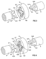
- the rotary driving coupling between the rotor shaft end 4 on the one hand and the pump shaft end 5 on the other hand takes place - as shown in the enlarged detail of FIG 2 and in particular according to FIG 3, 4 removable - cardan like, so that the rotor shaft end 4 with projecting flat driving lugs, especially two flat driving webs 4.1, 5.2 in corresponding driving grooves, in particular two-flight grooves 6.1, 6.2, of the coupling piece 6 and the pump shaft end 5 with two-flight rods 5.1; 5.2 in corresponding driving grooves, in particular two-flight grooves 6.3; 6.4, the coupling piece 6 can be inserted, opposite here for example, the first-mentioned driving people by 90 ° against are offset from each other.
- the coupling piece 6 can be inserted, opposite here for example, the first-mentioned driving people by 90 ° against are offset from each other.
- the coupling shaft and corresponding two-axis driving grooves on the rotor shaft end or at the pump shaft end also
- the rotor shaft end 4 and the pump shaft end 5 can be inserted under a low mutual pretension in the positive engagement plug-in receptacle of the coupling piece 6 which is designed as a driving groove 6.1-6.4.
- the driving surfaces are expediently provided with respect to both directions of rotation with appropriate conical design.
Landscapes
- Engineering & Computer Science (AREA)
- General Engineering & Computer Science (AREA)
- Mechanical Engineering (AREA)
- Power Engineering (AREA)
- Physics & Mathematics (AREA)
- Fluid Mechanics (AREA)
- Transportation (AREA)
- Valves And Accessory Devices For Braking Systems (AREA)
- Rotary Pumps (AREA)
Description
- Die Erfindung bezieht sich auf ein Motor-Pumpen-Aggregat gemäß Patentanspruch 1 oder 2 und eine Bremsvorrichtung für ein Kraftfahrzeug gemäß Patentanspruch 3.
- Ein Motor-Pumpen-Aggregat mit den Merkmalen des Oberbegriffs des Patentanspruchs 1 oder 2 ist durch die EP 0 645 875 B1 und durch US 4 049 364 bekannt. Die Pumpe ist bei einer Kraftfahrzeug-Bremsvorrichtung, insbesondere für eine ABS-Bremsvorrichtung, normalerweise als Hydraulikpumpe ausgebildet; dabei werden Pumpenstößel über Excenter von der Pumpenwelle angetrieben. Die Pumpenwelle ist als verlängertes einstückiges Rotorwellenende des Elektromotors ausgebildet.
- Aus dem Dokument DE 41 20 665 A1 ist ebenfalls eine elektromotorisch angetriebene Hydraulikpumpe bekannt, die zum Beispiel in einem Antiblockiersystem in einem Kraftfahrzeug eingesetzt wird. Dort ist die Pumpenwelle als selbständiges Pumpenbauteil mit einem Pumpenwellenende beim Zusammenbau von Elektromotor und Pumpe mit einem entsprechenden Rotorwellenende des Elektromotors gekuppelt.
- Zur gegenseitigen Ankupplung des abtriebsseitigen Pumpenwellenendes des Elektromotors einerseits mit dem antriebsseitigen Pumpenwellenende der Pumpe andererseits kann ein Kupplungsstück vorgesehen werden, dass eine kardangelenkartige Antriebsverbindung mit dem Rotorwellenende und dem Pumpenwellenende über jeweils eine formschlüssige axiale Steckaufnahme vorsieht. Eine solche Kupplung ist zum Beispiel aus dem Dokument GB 771,595 bekannt, wo die Kopplung zwischen der Welle einer elektrischen Maschine und einer Pumpeneinheit mit einem zusätzlichen kardangelenkartigen Kupplungsstück (Oldham coupling) offenbart ist.
- Gemäß Aufgabe vorliegender Erfindung soll eine gegenüber unerwünschten Drehschwingungen und Axialschüben geschützte Antriebsverbindung bei derartigen kardangelenkartigen Antriebsverbindungen mit axial gegenseitiger formschlüssiger Steckaufnahme von Rotorwellenende und Pumpenwellenende über ein Kupplungsstück vermieden werden.
- Die Lösung dieser Aufgabe gelingt erfindungsgemäß durch ein Motor-Pumpen-Aggregat gemäß Patentanspruch 1 oder 2 und einer Kraftfahrzeug-Bremsvorrichtung gemäß Patentanspruch 3.
- Ausgehend von der Erkenntnis, dass zu frühzeitigen Schäden führende Drehschwingungen und Axialschübe insbesondere durch Momentenschwankungen der Pumpe und durch ein radiales bzw. axiales Toleranzspiel zwischen den formschlüssig in dem Kupplungsstück in Mitnahme stehenden Enden der Rotorwelle bzw. der Pumpenwellen begründet sind, ist durch die erfindungsgemäße Konizität bei gleichzeitiger geringer gegenseitiger Vorspannung des Rotorwellenendes gegenüber dem Pumpenwellenende mit einfachen Mitteln eine fertigungsbedingte Lose zwischen den anzutreibenden Teilen im Kupplungsstück eliminierbar und sind aufgrund der dadurch gewährleisteten Spielfreiheit innerhalb des Kupplungsstücks die Momentenschwankungen, die durch die Bewegung auftreten und über das Kupplungsstück in den Motor eindringen und innerhalb dieses z.B. zu Wicklungsschäden führen, vermeidbar.
- Die Erfindung sowie vorteilhafte Ausgestaltungen der Erfindung werden im folgenden anhand schematischer Ausführungsbeispiele in der Zeichnung näher erläutert; darin zeigen:
- FIG 1
- in einem axialen Teilschnittbild ein komplett montiertes Motor-Pumpen-Aggregat;
- FIG 2
- in einem vergrößerten Ausschnitt aus FIG 1 die gegenseitige kardengelenkartige Drehmitnahmeverbindung des Rotorwellenendes des Elektromotor einerseits und des Pumpenwellenendes der Pumpe andererseits über ein Kupplungsstück;
- FIG 3
- in perspektivisch vergrößertem Ausschnitt aus FIG 2 eine kardangelenkartige Steckaufnahme mit einer konischen Ausbildung der Flach-Mitnahmestege des Rotorwellenendes bzw. des Pumpenwellenendes und einer Ausbildung der korrespondierenden Mitnahmenuten des Kupplungsstückes
- FIG 4
- in einem perspektivisch vergrößerten Ausschnitt aus FIG 2 eine kardangelenkartigen Steckaufnahme mit einer konischen Ausbildung der Mitnahmenuten des Kupplungsstückes und einer Ausbildung der Flach-Mitnahmestege des Rotorwellenendes bzw. des Pumpenwellenendes.
- FIG 1 zeigt in einem axialen Teilschnittbild ein komplettes, z. B. für eine Kraftfahrzeug-Antiblockier-Bremsvorrichtung einsetzbares, Motor-Pumpen-Aggregat. An einen Elektromotor 1 ist stirnseitig und axial fluchtend eine Pumpe 2 für eine Brems-Hydraulikflüssigkeit angeflanscht und an der anderen Stirnfläche der Pumpe 2 ein Elektronikgehäuse 3 angebaut, dass eine - hier nicht gesonderte dargestellte, jedoch z.B. aus der EP 0 695 875 B1 bekannte - Anschlusseinheit, insbesondere eine elektrische bzw. elektronische Versorgungs- bzw. Steuereinheit, aufnimmt und über eine Anschlussverbindung 1.1 mit den Steuer- bzw. Versorgungsanschlüssen des Elektromotors 1 in Verbindung steht.
- Der Elektromotor 1 weist ein pumpenseitiges Rotorwellenende 4 auf, das über ein Kupplungsstück 6 mit einem Pumpenwellenende 5 der Pumpe 2, z.B. beim axialen Zusammenbau von Elektromotor 1 und Pumpe 2, gekuppelt ist.
- Die Drehmitnahme-Kupplung zwischen dem Rotorwellenende 4 einerseits und dem Pumpenwellenende 5 andererseits erfolgt - wie aus dem vergrößerten Ausschnitt gemäß FIG 2 und insbesondere gemäß FIG 3, 4 entnehmbar - kardangelenkartig, derart dass das Rotorwellenende 4 mit vorstehenden Flach-Mitnahmestegen, insbesondere Zweiflach-Mitnahmestegen 4.1;4.2 in entsprechende Mitnahmenuten, insbesondere Zweiflach-Mitnahmenuten 6.1;6.2, des Kupplungsstückes 6 und das Pumpenwellenende 5 mit Zweiflach-Mitnahmestegen 5.1;5.2 in korrespondierende Mitnahmenuten, insbesondere Zweiflach-Mitnahmenuten 6.3;6.4, des Kupplungsstückes 6 einsteckbar ist, die hier gegenüber den erstgenannten Mitnahmenuten beispielsweise um 90° gegen einander versetzt sind. Anstelle der in FIG 3,4 dargestellten Ausführung können auch im konstruktiven Umkehrprinzip Flach-Mitnahmestege an dem Kupplungsstück und korrespondierende Zweiflach-Mitnahmenuten an dem Rotorwellenende bzw. an dem Pumpenwellenende vorgesehen sein.
- In den in den FIG 2-4 dargestellten Ausführungsvarianten sind das Rotorwellenende 4 und das Pumpenwellenende 5 unter geringer gegenseitiger Vorspannung in die als Mitnahmenut 6.1-6.4 ausgeführte, formschlüssige Steckaufnahme des Kupplungsstückes 6 einsteckbar.
- Gemäß FIG 3 weisen die Zweiflach-Mitnahmestege 4.1;4.2 bzw. 5.1;5.2 an ihren bei einer Drehmitnahme wirksamen, an dem Kupplungsstück 6 anliegenden Mitnahmeflächen 4.11;4.21 bzw. 5.11 bzw.5.21 eine derartige konische Ausbildung auf, dass sie durch die gegenseitige leichte Vorspannung an den korrespondierenden planverlaufenden Mitnahmeflächen der Mitnahmenuten 6.1-6.4 mit Sicherheit zu einer spielfreien Anlage kommen. Die Mitnahmeflächen sind zweckmäßigerweise hinsichtlich beider Drehrichtungen mit entsprechender konischer Ausbildung versehen.
- FIG 4 zeigt das grundsätzlich gleiche Lösungsprinzip gemäß FIG 3, jedoch ist die konische Ausbildung nunmehr an den zur Mitnahme zur Anlage kommenden Mitnahmeflächen 6.11-6.41 der Zweiflach-Mitnahmenuten 6.1-6.4 des Kupplungsstückes 6 vorgesehen und sind die Mitnahmeflächen der Zweiflach-Mitnahmestege 4.1;4.2 bzw. 5.1;5.2 des Rotorwellenendes 4 bzw. des Pumpenwellenendes 5 ohne gesonderte Bearbeitung hinsichtlich einer Konizität flachverlaufend ausgebildet.
Claims (3)
- Motor-Pumpen-Aggregat, insbesondere für eine Kraftfahrzeug-Bremsvorrichtung,- mit einem Elektromotor (1) und einer von diesem angetriebenen, axial nachgeordneten Pumpe (2); dadurch gekennzeichnet, daß- eine kardangelenkartige Antriebsverbindung zwischen dem Elektromotor (1) und der Pumpe (2) über ein Kupplungsstück (6) mit jeweils einer formschlüssigen Steckaufnahme für ein abtriebsseitiges Rotorwellenende (4) des Elektromotors (1) und für ein antriebsseitiges Pumpenwellenende (5) der Pumpe (2) vorgesehen ist,- eine Ausbildung der Steckaufnahme durch axial vorstehende, radial verlaufende Flach-Mitnahmestege (4.1;4.2 bzw. 5.1;5.2) an dem Rotorwellenende (4) und an dem Pumpenwellenende (5) einerseits oder an dem Kupplungsstück (6) andererseits und korrespondierende Flach-Mitnahmenuten (6.1-6.4), an dem Kupplungsstück (6) bzw. an dem Rotorwellenende (4) und an dem Pumpenwellenende (5) vorgesehen ist,- eine axial konische Ausbildung der Steckaufnahme durch axial konische Anordnung der an dem Kupplungsstück(6) anliegenden Mitnahmeflächen (4.11;4.21 bzw. 5.11; 5.21) der Flach-Mitnahmestege (4.1; 4.2 bzw. 5.1;5.2), und einer axial planen Anordnung der korrespondierenden Mitnahmeflächen der Mitnahmenuten (6.1-6.4) vorgesehen ist und dass- eine gegenseitige axiale Vorspannung des Rotorwellenendes (4) und des Pumpenwellenendes (5) im Sinne einer spielfreien Drehmitnahme vorgesehen ist.
- Motor-Pumpen-Aggregat, insbesondere für eine Kraftfahrzeug-Bremsvorrichtung,- mit einem Elektromotor (1) und einer von diesem angetriebenen, axial nachgeordneten Pumpe (2); dadurch gekennzeichnet, dass- eine kardangelenkartige Antriebsverbindung zwischen dem Elektromotor (1) und der Pumpe (2) über ein Kupplungsstück (6) mit jeweils einer formschlüssigen Steckaufnahme für ein abtriebsseitiges Rotorwellenende (4) des Elektromotors (1) und für ein antriebsseitiges Pumpenwellenende (5) der Pumpe (2) vorgesehen ist,- eine Ausbildung der Steckaufnahme durch axial vorstehende, radial verlaufende Flach-Mitnahmestege (4.1;4.2 bzw. 5.1;5.2) an dem Rotorwellenende (4) und an dem Pumpenwellenende (5) einerseits oder an dem Kupplungsstück (6) andererseits und korrespondierende Flach-Mitnahmenuten (6.1-6.4), an dem Kupplungsstück (6) bzw. an dem Rotorwellenende (4) und an dem Pumpenwellenende (5) vorgesehen ist,- eine axial konische Ausbildung der Steckaufnahme durch axial konische Anordnung der an den Flach-Mitnahmestegen (4.1;4.2 bzw. 5.1;5.2) anliegenden Mitnahmeflächen (6.11-6.41) der Mitnahmenuten (6.1-6.4) und einer axial planen Anordnung der korrespondierenden Mitnahmeflächen (4.11;4.21 bzw. 5.11;5.21) der Mitnahmestege (4.1;4.2 bzw. 5.1;5.2) vorgesehen ist und dass- eine gegenseitige axiale Vorspannung des Rotorwellenendes (4) und des Pumpenwellenendes (5) im Sinne einer spielfreien Drehmitnahme vorgesehen ist.
- Bremsvorrichtung für ein Kraftfahrzeug, insbesondere ABS-Bremsvorrichtung- mit einem Motor-Pumpen-Aggregat mit den Merkmalen aus zumindest einem der Ansprüche 1 oder 2.
Priority Applications (3)
| Application Number | Priority Date | Filing Date | Title |
|---|---|---|---|
| DE50208947T DE50208947D1 (de) | 2002-02-27 | 2002-02-27 | Motor-Pumpen-Aggregat, insbesondere für eine Kraftfahrzeug-Bremsvorrichtung |
| EP02004529A EP1341290B1 (de) | 2002-02-27 | 2002-02-27 | Motor-Pumpen-Aggregat, insbesondere für eine Kraftfahrzeug-Bremsvorrichtung |
| US10/375,607 US20030180163A1 (en) | 2002-02-27 | 2003-02-27 | Motor/pump assembly for use in a braking device |
Applications Claiming Priority (1)
| Application Number | Priority Date | Filing Date | Title |
|---|---|---|---|
| EP02004529A EP1341290B1 (de) | 2002-02-27 | 2002-02-27 | Motor-Pumpen-Aggregat, insbesondere für eine Kraftfahrzeug-Bremsvorrichtung |
Publications (2)
| Publication Number | Publication Date |
|---|---|
| EP1341290A1 EP1341290A1 (de) | 2003-09-03 |
| EP1341290B1 true EP1341290B1 (de) | 2006-12-13 |
Family
ID=27675649
Family Applications (1)
| Application Number | Title | Priority Date | Filing Date |
|---|---|---|---|
| EP02004529A Expired - Lifetime EP1341290B1 (de) | 2002-02-27 | 2002-02-27 | Motor-Pumpen-Aggregat, insbesondere für eine Kraftfahrzeug-Bremsvorrichtung |
Country Status (3)
| Country | Link |
|---|---|
| US (1) | US20030180163A1 (de) |
| EP (1) | EP1341290B1 (de) |
| DE (1) | DE50208947D1 (de) |
Cited By (7)
| Publication number | Priority date | Publication date | Assignee | Title |
|---|---|---|---|---|
| CN109113960A (zh) * | 2017-06-26 | 2019-01-01 | 比亚迪股份有限公司 | 电动油泵总成、转向系统和润滑系统 |
| CN109113959A (zh) * | 2017-06-26 | 2019-01-01 | 比亚迪股份有限公司 | 电动油泵总成、转向系统和润滑系统 |
| CN109113949A (zh) * | 2017-06-26 | 2019-01-01 | 比亚迪股份有限公司 | 电动油泵总成、转向系统和润滑系统 |
| CN109113955A (zh) * | 2017-06-26 | 2019-01-01 | 比亚迪股份有限公司 | 电动油泵总成、转向系统和润滑系统 |
| CN109113961A (zh) * | 2017-06-26 | 2019-01-01 | 比亚迪股份有限公司 | 电动油泵总成、转向系统和润滑系统 |
| CN109113962A (zh) * | 2017-06-26 | 2019-01-01 | 比亚迪股份有限公司 | 电动油泵总成、转向系统和润滑系统 |
| DE102023126956A1 (de) * | 2023-10-04 | 2025-04-10 | Bayerische Motoren Werke Aktiengesellschaft | Rotorwelle für eine elektrische maschine |
Families Citing this family (15)
| Publication number | Priority date | Publication date | Assignee | Title |
|---|---|---|---|---|
| US6875114B2 (en) * | 2003-03-21 | 2005-04-05 | Kelsey-Hayes Company | Tapered coupling |
| US20040185945A1 (en) * | 2003-03-21 | 2004-09-23 | Barron Richard J. | Tapered slot coupling |
| WO2007060066A1 (de) | 2005-11-24 | 2007-05-31 | Continental Automotive Gmbh | Motor-pumpen-aggregat mit verbesserter dichtung |
| DE102008063983A1 (de) * | 2008-12-19 | 2010-07-01 | Dürr Systems GmbH | Pumpe zum Fördern eines Fluids, insbesondere Dosierpumpe |
| DE102008064727B3 (de) | 2008-12-19 | 2024-06-27 | Dürr Systems Ag | Pumpe zum Fördern eines Fluids, insbesondere Dosierpumpe |
| DE102011075278A1 (de) * | 2010-07-16 | 2012-02-23 | Baumüller Nürnberg GmbH | Pumpenaggregat |
| WO2015068107A1 (en) * | 2013-11-05 | 2015-05-14 | Ashot Ashkelon Industries Ltd. | Bevel universal joint |
| JP6330218B2 (ja) | 2014-03-05 | 2018-05-30 | 株式会社デンソー | ジョイント装置及びモータ |
| KR101601070B1 (ko) * | 2014-06-11 | 2016-03-08 | 현대자동차주식회사 | 자동변속기용 오일펌프 |
| KR101601072B1 (ko) * | 2014-06-16 | 2016-03-08 | 현대자동차주식회사 | 자동변속기용 오일펌프 |
| JP6536015B2 (ja) * | 2014-11-12 | 2019-07-03 | 株式会社デンソー | ジョイント構造、クラッチ及びモータ |
| WO2017013932A1 (ja) * | 2015-07-21 | 2017-01-26 | 日立オートモティブシステムズ株式会社 | ポンプ装置 |
| US20170298920A1 (en) * | 2016-03-30 | 2017-10-19 | Flow Control LLC | Modular bib pump |
| DE102018124225A1 (de) * | 2018-04-10 | 2019-10-10 | Schaeffler Technologies AG & Co. KG | Pumpenaktor für eine Kupplung und entsprechende Kupplung |
| DE102023115059A1 (de) * | 2023-06-07 | 2024-12-12 | B.Braun Avitum Ag | Aufsteck- und Sicherungsvorrichtung des Rotors einer peristaltischen Blutpumpe |
Family Cites Families (11)
| Publication number | Priority date | Publication date | Assignee | Title |
|---|---|---|---|---|
| US1244533A (en) * | 1915-02-02 | 1917-10-30 | Morse Chain Co | Shaft-coupling. |
| US1488497A (en) * | 1922-02-07 | 1924-04-01 | Higgins Eugene | Shaft coupling |
| GB771595A (en) * | 1953-09-23 | 1957-04-03 | Simms Motor Units Ltd | Improvements relating to dynamo-rotary pump combinations |
| FR1492986A (fr) * | 1966-07-08 | 1967-08-25 | Luxembourg Brev Participations | Perfectionnements apportés aux accouplements élastiques |
| US4049364A (en) * | 1974-07-01 | 1977-09-20 | Ace Envelope Manufacturing Corporation | Removable impeller assembly for printing press centrifugal pump |
| US4941861A (en) * | 1987-12-28 | 1990-07-17 | Electronic Instrument & Specialty Corp. | Interlocking shaft coupling |
| US5022645A (en) * | 1988-11-25 | 1991-06-11 | Eastman Kodak Company | Disengageable coupling usable in a sheet transport mechanism |
| JP2537305Y2 (ja) * | 1992-08-21 | 1997-05-28 | 株式会社ケイセブン | 軸継手 |
| US5895207A (en) * | 1993-06-17 | 1999-04-20 | Itt Automotive Europe, Gmbh | Electric motor-pump assembly |
| JPH10327566A (ja) * | 1997-05-23 | 1998-12-08 | Matsushita Electric Ind Co Ltd | 小型モータ |
| US6241489B1 (en) * | 1999-10-08 | 2001-06-05 | Kelsey-Hayes Company | Internal electrical connector for a hydraulic control unit |
-
2002
- 2002-02-27 DE DE50208947T patent/DE50208947D1/de not_active Expired - Lifetime
- 2002-02-27 EP EP02004529A patent/EP1341290B1/de not_active Expired - Lifetime
-
2003
- 2003-02-27 US US10/375,607 patent/US20030180163A1/en not_active Abandoned
Cited By (9)
| Publication number | Priority date | Publication date | Assignee | Title |
|---|---|---|---|---|
| CN109113960A (zh) * | 2017-06-26 | 2019-01-01 | 比亚迪股份有限公司 | 电动油泵总成、转向系统和润滑系统 |
| CN109113959A (zh) * | 2017-06-26 | 2019-01-01 | 比亚迪股份有限公司 | 电动油泵总成、转向系统和润滑系统 |
| CN109113949A (zh) * | 2017-06-26 | 2019-01-01 | 比亚迪股份有限公司 | 电动油泵总成、转向系统和润滑系统 |
| CN109113955A (zh) * | 2017-06-26 | 2019-01-01 | 比亚迪股份有限公司 | 电动油泵总成、转向系统和润滑系统 |
| CN109113961A (zh) * | 2017-06-26 | 2019-01-01 | 比亚迪股份有限公司 | 电动油泵总成、转向系统和润滑系统 |
| CN109113962A (zh) * | 2017-06-26 | 2019-01-01 | 比亚迪股份有限公司 | 电动油泵总成、转向系统和润滑系统 |
| CN109113962B (zh) * | 2017-06-26 | 2020-06-19 | 比亚迪股份有限公司 | 电动油泵总成、转向系统和润滑系统 |
| CN109113949B (zh) * | 2017-06-26 | 2020-06-19 | 比亚迪股份有限公司 | 电动油泵总成、转向系统和润滑系统 |
| DE102023126956A1 (de) * | 2023-10-04 | 2025-04-10 | Bayerische Motoren Werke Aktiengesellschaft | Rotorwelle für eine elektrische maschine |
Also Published As
| Publication number | Publication date |
|---|---|
| US20030180163A1 (en) | 2003-09-25 |
| EP1341290A1 (de) | 2003-09-03 |
| DE50208947D1 (de) | 2007-01-25 |
Similar Documents
| Publication | Publication Date | Title |
|---|---|---|
| EP1341290A1 (de) | Motor-Pumpen-Aggregat, insbesondere Kraftfahrzeug-Bremsvorrichtung | |
| DE10015139A1 (de) | Motorpumpenaggregat | |
| WO2008034768A1 (de) | Wellenkupplung | |
| EP2473740A1 (de) | Zweistufige kreiselpumpe | |
| WO1999060271A1 (de) | Motorpumpenaggregat | |
| DE102017222754A1 (de) | Gerotor Pumpe | |
| EP0666422B1 (de) | Lagerung und Antrieb der Rotoren eines Schraubenrotorverdichters | |
| WO1998053202A1 (de) | Pumpenaggregat, insbesondere für schlupfgeregelte bremsanlagen von fahrzeugen | |
| EP3306057B1 (de) | Aktuator zur verstellung von klappen für eine verbrennungskraftmaschine | |
| DE4028416A1 (de) | Eine anlaufhilfe aufweisender synchronmotor | |
| DE3202993A1 (de) | Drehkolbenmaschine | |
| EP0913598A1 (de) | Drehmomentwandleranbindung mit Schwingungsdämpfer | |
| EP2569525B1 (de) | Vorrichtung zum antrieb eines nebenaggregates | |
| DE29603748U1 (de) | Kraftfahrzeug-Antrieb mit einem Elektromotor | |
| EP1318925A1 (de) | Antriebsvorrichtung, insbesondere für ein kraftfahrzeug | |
| DE10149388A1 (de) | Fluidpumpe, insbesondere Hydraulik- oder Schmiermittelpumpe, für eine Brennkraftmaschine, sowie Baueinheit aus mindestens zwei Fluidpumpen für eine Brennkraftmaschine | |
| WO2024028294A1 (de) | Pumpe, insbesondere getriebeölpumpe | |
| EP0999083A3 (de) | Antriebsachse mit eingebautem Elektromotor | |
| DE102011013918A1 (de) | Kupplungsvorrichtung mit einer eintreibenden und einer abtreibenden Welle und Antrieb | |
| DE102016119091A1 (de) | Aktuator für eine Verbrennungskraftmaschine | |
| EP1053408A1 (de) | Hirth-verzahntes maschinenelement | |
| DE19607735A1 (de) | Verfahren zum Zusammenbau eines Kraftfahrzeug-Antriebes mit einem Elektromotor | |
| DE102005032644A1 (de) | Zahnradpumpe, insbesondere Zahnradölpumpe für Fahrzeuge | |
| EP1389825A2 (de) | Antriebsmotoranordnung, insbesondere für ein Kraftfahrzeug | |
| EP4565769A1 (de) | Pumpe, insbesondere getriebeölpumpe |
Legal Events
| Date | Code | Title | Description |
|---|---|---|---|
| PUAI | Public reference made under article 153(3) epc to a published international application that has entered the european phase |
Free format text: ORIGINAL CODE: 0009012 |
|
| AK | Designated contracting states |
Kind code of ref document: A1 Designated state(s): AT BE CH CY DE DK ES FI FR GB GR IE IT LI LU MC NL PT SE TR |
|
| AX | Request for extension of the european patent |
Extension state: AL LT LV MK RO SI |
|
| 17P | Request for examination filed |
Effective date: 20040119 |
|
| 17Q | First examination report despatched |
Effective date: 20040310 |
|
| AKX | Designation fees paid |
Designated state(s): DE FR IT |
|
| RTI1 | Title (correction) |
Free format text: MOTOR-PUMP ASSEMBLY, IN PARTICULAR FOR A VEHICLE BRAKING SYSTEM |
|
| GRAP | Despatch of communication of intention to grant a patent |
Free format text: ORIGINAL CODE: EPIDOSNIGR1 |
|
| GRAS | Grant fee paid |
Free format text: ORIGINAL CODE: EPIDOSNIGR3 |
|
| GRAA | (expected) grant |
Free format text: ORIGINAL CODE: 0009210 |
|
| AK | Designated contracting states |
Kind code of ref document: B1 Designated state(s): DE FR IT |
|
| REF | Corresponds to: |
Ref document number: 50208947 Country of ref document: DE Date of ref document: 20070125 Kind code of ref document: P |
|
| ET | Fr: translation filed | ||
| PLBE | No opposition filed within time limit |
Free format text: ORIGINAL CODE: 0009261 |
|
| STAA | Information on the status of an ep patent application or granted ep patent |
Free format text: STATUS: NO OPPOSITION FILED WITHIN TIME LIMIT |
|
| 26N | No opposition filed |
Effective date: 20070914 |
|
| REG | Reference to a national code |
Ref country code: FR Ref legal event code: TP Owner name: BROSE FAHRZEUGTEILE GMBH & CO. KOMMANDITGESELL, DE Effective date: 20120125 |
|
| REG | Reference to a national code |
Ref country code: FR Ref legal event code: PLFP Year of fee payment: 15 |
|
| REG | Reference to a national code |
Ref country code: FR Ref legal event code: PLFP Year of fee payment: 16 |
|
| PGFP | Annual fee paid to national office [announced via postgrant information from national office to epo] |
Ref country code: IT Payment date: 20170221 Year of fee payment: 16 |
|
| REG | Reference to a national code |
Ref country code: FR Ref legal event code: PLFP Year of fee payment: 17 |
|
| PGFP | Annual fee paid to national office [announced via postgrant information from national office to epo] |
Ref country code: DE Payment date: 20180228 Year of fee payment: 17 |
|
| PGFP | Annual fee paid to national office [announced via postgrant information from national office to epo] |
Ref country code: FR Payment date: 20180111 Year of fee payment: 17 |
|
| PG25 | Lapsed in a contracting state [announced via postgrant information from national office to epo] |
Ref country code: IT Free format text: LAPSE BECAUSE OF NON-PAYMENT OF DUE FEES Effective date: 20180227 |
|
| REG | Reference to a national code |
Ref country code: DE Ref legal event code: R119 Ref document number: 50208947 Country of ref document: DE |
|
| PG25 | Lapsed in a contracting state [announced via postgrant information from national office to epo] |
Ref country code: DE Free format text: LAPSE BECAUSE OF NON-PAYMENT OF DUE FEES Effective date: 20190903 |
|
| PG25 | Lapsed in a contracting state [announced via postgrant information from national office to epo] |
Ref country code: FR Free format text: LAPSE BECAUSE OF NON-PAYMENT OF DUE FEES Effective date: 20190228 |