EP1341255A1 - Antennenmodul und Lichtmast mit einem solchen Antennenmodul - Google Patents
Antennenmodul und Lichtmast mit einem solchen Antennenmodul Download PDFInfo
- Publication number
- EP1341255A1 EP1341255A1 EP02004146A EP02004146A EP1341255A1 EP 1341255 A1 EP1341255 A1 EP 1341255A1 EP 02004146 A EP02004146 A EP 02004146A EP 02004146 A EP02004146 A EP 02004146A EP 1341255 A1 EP1341255 A1 EP 1341255A1
- Authority
- EP
- European Patent Office
- Prior art keywords
- antenna module
- column
- light pole
- module according
- antenna
- Prior art date
- Legal status (The legal status is an assumption and is not a legal conclusion. Google has not performed a legal analysis and makes no representation as to the accuracy of the status listed.)
- Granted
Links
Images


Classifications
-
- H—ELECTRICITY
- H01—ELECTRIC ELEMENTS
- H01Q—ANTENNAS, i.e. RADIO AERIALS
- H01Q1/00—Details of, or arrangements associated with, antennas
- H01Q1/44—Details of, or arrangements associated with, antennas using equipment having another main function to serve additionally as an antenna, e.g. means for giving an antenna an aesthetic aspect
-
- H—ELECTRICITY
- H01—ELECTRIC ELEMENTS
- H01Q—ANTENNAS, i.e. RADIO AERIALS
- H01Q1/00—Details of, or arrangements associated with, antennas
- H01Q1/12—Supports; Mounting means
- H01Q1/1242—Rigid masts specially adapted for supporting an aerial
-
- H—ELECTRICITY
- H01—ELECTRIC ELEMENTS
- H01Q—ANTENNAS, i.e. RADIO AERIALS
- H01Q1/00—Details of, or arrangements associated with, antennas
- H01Q1/12—Supports; Mounting means
- H01Q1/22—Supports; Mounting means by structural association with other equipment or articles
- H01Q1/24—Supports; Mounting means by structural association with other equipment or articles with receiving set
- H01Q1/241—Supports; Mounting means by structural association with other equipment or articles with receiving set used in mobile communications, e.g. GSM
- H01Q1/246—Supports; Mounting means by structural association with other equipment or articles with receiving set used in mobile communications, e.g. GSM specially adapted for base stations
Definitions
- the present invention relates to an antenna module for Attachment to a building, especially a light pole.
- the invention further relates to a light pole, which is provided with at least one such antenna module is.
- Mobile network operators are dependent on transmit and receive antennas at regular intervals to set up a nationwide telephone network with as few so-called dead spots to the users to provide.
- One problem with this is suitable locations for such antennas, for example to be found on high-rise buildings in a suitable location, especially since such locations are sometimes very expensive to pay have to.
- Another difficulty is the assembly the antenna that is on site at the appropriate building takes place, which leads to the known antennas after Represent type of television antennas.
- this object is achieved by an antenna module for mounting on a building, in particular a light pole, with a central column, the fasteners for attaching transmitting and / or receiving antennas in particular for telecommunications and from a veneer from a radio-wave-permeable Material is surrounded, at the base end and / or on upper end of the column coupling means are provided to to attach the antenna module to a building or with to connect another antenna module.
- the invention is therefore based on the general consideration as a location for transmitting and receiving antennas in particular for the mobile radio area, larger light poles to be used, such as at football stadiums or the like are already available anyway.
- the invention creates a standard antenna module with a central pillar on which the actual broadcast and / or receiving antennas are attached, and one the pillar surrounding veneer, which is both a privacy screen forms, as well as the antennas and supply lines etc. protects against environmental influences.
- This standard antenna module can be completely pre-assembled and over the coupling means provided at the base end on the light pole be attached.
- the invention offers the possibility of several Then build antenna modules to a tower corresponding coupling agent, for example in the form of Coupling flanges at the base end and also at the upper end the column are provided for easy assembly guarantee.
- a coupling agent for example in the form of Coupling flanges at the base end and also at the upper end the column are provided for easy assembly guarantee.
- the antennas of different mobile operators each can be mounted in a module, whereby also retrofitting can be carried out in a simple manner can.
- the invention provided that the cross section the facing of each antenna module from the base end tapered towards the upper end, the outer contours of the Coverings of two adjacent antenna modules are expediently chosen so that the transition is flowing between the two antenna modules.
- the outer contours of the light pole can also be used in the same way and the antenna modules to be adapted to each other that the transition from the light pole to the antenna module attached to it runs essentially fluently.
- the delusion that is basically any Can have cross-section, but preferably has a round or square cross section, must a radio wave permeable material, wherein preferably a plastic material is used, the has the required stability and light weight.
- This veneer is according to one embodiment the invention hung on the column and guyed.
- a support can be attached to the top of the column on which the blind is hung, and another support is provided at the base end of the column be positioned at the lower end of the column. It is essential that the carrier at the top and lower end of the column at least in its with the Veneer in contacting areas as well a radio wave permeable material such as Plastic exist, so that the reception and transmission properties not be affected.
- the column Fasteners provided to antennas with an offset 120 ° apart on the circumference of the column.
- Such an offset of 120 ° ensures good Send and receive properties in all directions.
- the column Attachment pipes to which the antennas are attached can be tightened.
- the column cable holders and / or cable guides provided for the necessary connecting cables are expedient on the column cable holders and / or cable guides provided for the necessary connecting cables.
- FIG. 1 and 2 is a light pole 1 according to the present Invention shown as he for example used to illuminate soccer stadiums etc.
- This light pole 1 is in a manner known per se several superimposed mast elements 1a to 1e formed, which are welded together.
- the outer shell or panel 2 of the light pole 1 consists of an aluminum material and is inside by a Grid 3 stiffened by reinforcing struts.
- About in the middle Height of the light pole 1 are several lighting fixtures 4 attached to the panel 2, the top towards light against two provided at the top of the light pole Radiate reflectors 5 indirectly to a surface to illuminate.
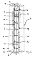
- each antenna module has 6 a central pillar 7, which at its base end and a coupling flange 8, 9 at its upper end for connection to a further antenna module 6 or with the upper end of the light pole 1.
- the pillar 7 carries three mounting tubes 10, which extend in the longitudinal direction of the column extend and evenly distributed along the circumference of column 7, i.e. with 120 ° offset attached to each other on the column 7 via fastening rings 17 are.
- On the mounting tubes 10 are one above the other two transmit / receive antennas 11 each for the area Mobile communications provided.
- the total of six antennas 11 form two superimposed antenna sets for each a cellular network.
- the top Antenna set intended for the German D1 mobile network and the lower antenna set for the UMTS area be responsible.
- antennas can of course also be used be available for other purposes.
- the antennas 11 are on the mounting tubes 10 by means of appropriate mounting clamps 12 clamped.
- the column 7 with the antennas 11, cable holders provided thereon 13 etc. is surrounded by a blind 14, made of a radio wave permeable plastic material consists.
- the facing 14 is suspended on the column and braced.
- the connecting flanges 8, 9 each provided plastic carrier 15, 16, wherein the facing 14 is attached to the upper support 16 and positioned and stabilized by the lower bracket 15 becomes.
- the carriers 15, 16 are cruciform, each of the four support arms 18 with a corner region of the Facing 14 is in contact.
- Figures 3 and 4 show that the veneer 14 has a square cross section, which differs from Base end tapers towards the upper end of the antenna module 6.
- the dimensions are chosen so that the Cross-sectional area of the facing 14 at the base end of the Antenna module 6 each have the cross section of the upper end of the underlying antenna module 6 or the upper one End of the light pole 1 corresponds, so that the transitions between the light tower 1 and the antenna module tower on the one hand and on the other hand between the individual antenna modules 6 runs fluently and the invention
- Light / antenna mast that shown in Figures 1 and 2, outer contour tapering evenly upwards receives.
- the light / antenna mast according to the invention with several Antenna modules 6 arranged one above the other Possibility created the antennas of several mobile operators to install on a single light pole 1, in each antenna module 6 the antennas of a Provider can be accommodated. Due to the modular It is possible to set up antenna modules at any time remove or retrofit new antenna modules 6, where the assembly by the end of the Column 7 provided connecting flanges 8, 9 very simple designed. Due to the aerodynamic outer contour it is possible to realize a large height without that the light / antenna mast is overstressed statically.
Abstract
Description
- Figur 1
- einen Lichtmast gemäß der vorliegenden Erfindung in Vorderansicht,
- Figur 2
- in teilweise geschnittener Seitenansicht den Lichtmast aus Figur 1 in etwas verkleinertem Maßstab,
- Figur 3
- ein Antennenmodul des kombinierten Licht/Antennenmastes aus den Figuren 1 und 2 in perspektivischer Ansicht und
- Figur 4
- das Antennenmodul aus Figur 3 im Querschnitt.
Claims (18)
- Antennenmodul zur Anbringung auf einem Bauwerk, insbesondere einem Lichtmast (1), mit einer zentralen Säule (7), die Befestigungsmittel (10) zur Anbringung von Sende- und/oder Empfangsantennen (11) insbesondere für die Telekommunikation aufweist und von einer Verblendung (14) aus einem funkwellendurchlässigen Material umgeben ist, wobei am Basisende und/oder am oberen Ende der Säule (7) Kupplungsmittel (8, 9) vorgesehen sind, um das Antennenmodul (6) an einem Bauwerk anzubringen oder mit einem weiteren Antennenmodul (6) zu verbinden.
- Antennenmodul nach Anspruch 1, dadurch gekennzeichnet, daß die Verblendung (14) aus einem Kunststoffmaterial besteht.
- Antennenmodul nach Anspruch 1 oder 2, dadurch gekennzeichnet, daß die Verblendung (14) an der Säule (7) eingehängt und abgespannt ist.
- Antennenmodul nach Anspruch 3, dadurch gekennzeichnet, daß am oberen Ende der Säule (7) ein Träger (16) angebracht ist, an welchem die Verblendung (14) aufgehängt ist, und am Basisende der Säule (7) ein weiterer Träger (15) vorgesehen ist, der die Verblendung (14) am unteren Ende positioniert.
- Antennenmodul nach Anspruch 4, dadurch gekennzeichnet, daß die Träger (15, 16) zumindest in ihren mit der Verblendung (14) in Kontakt kommenden Bereichen aus einem funkwellendurchlässigen Material, insbesondere einem Kunststoffmaterial bestehen.
- Antennenmodul nach einem der vorherigen Ansprüche, dadurch gekennzeichnet, daß der Querschnitt der Verblendung (14) sich vom Basisende zum oberen Ende hin verjüngt.
- Antennenmodul nach einem der vorherigen Ansprüche, dadurch gekennzeichnet, daß die Verblendung (14) einen quadratischen Querschnitt besitzt.
- Antennenmodul nach einem der vorherigen Ansprüche, dadurch gekennzeichnet, daß die Befestigungsmittel (10) an der Säule (7) vorgesehen sind, um Antennen (11) mit einem Versatz von 120° zueinander am Umfang der Säule (7) verteilt anzuordnen.
- Antennenmodul nach Anspruch 8, dadurch gekennzeichnet, daß die Befestigungsmittel (10) geeignet sind, um zwei Sätze von drei um 120° zueinander versetzten Antennen (11) übereinander an der Säule (7) anzubringen.
- Antennenmodul nach einem der vorherigen Ansprüche, dadurch gekennzeichnet, daß als Befestigungsmittel an der Säule (7) Befestigungsrohre (10) angebracht sind, an denen die Antennen (11) festgespannt werden können.
- Antennenmodul nach Anspruch 10, dadurch gekennzeichnet, daß am Umfang der Säule (7) verteilt mit jeweils 120° Versatz zueinander drei Befestigungsrohre (10) angebracht sind, die sich im wesentlichen über die gesamte Länge der Säule (7) erstrecken.
- Antennenmodul nach einem der vorherigen Ansprüche, dadurch gekennzeichnet, daß an der zentralen Säule (7) Kabelhalterungen und/oder Kabelführungen (13) angebracht sind.
- Antennenmodul nach einem der vorherigen Ansprüche, dadurch gekennzeichnet, daß die Kupplungsmittel am Basisende und/oder am oberen Ende der Säule als Kupplungsflansche (8, 9) ausgebildet sind.
- Lichtmast mit mehreren daran angebrachten Beleuchtungskörpern (4), dadurch gekennzeichnet, daß am oberen Ende des Lichtmasts (1) ein Antennenmodul (6) nach einem der vorherigen Ansprüche angebracht ist.
- Lichtmast nach Anspruch 14, dadurch gekennzeichnet, daß die Verkleidung (2) des Lichtmasts (1) und die Verblendung (14) des Antennenmoduls (6) eine aneinander angepaßte Kontur besitzen derart, daß der Übergang vom Lichtmast (1) zu dem daran fixierten Antennenmodul (6) im wesentlichen fließend ist.
- Lichtmast nach Anspruch 14 oder 15, dadurch gekennzeichnet, daß ein Antennenturm bestehend aus mehreren übereinander angeordneten und miteinander verbundenen Antennenmodulen (6) an dem Lichtmast (1) befestigt sind.
- Lichtmast nach Anspruch 16, dadurch gekennzeichnet, daß die Außenkontur der Verblendungen (14) der Antennenmodule so gewählt ist, daß der Übergang zwischen zwei aneinandergrenzenden Antennenmodulen (6) fließend ist.
- Lichtmast nach einem der Ansprüche 14 bis 17, dadurch gekennzeichnet, daß am oberen Ende des Lichtmastes (1) Reflektoren (5) vorgesehen sind und die Beleuchtungskörper (4) nach oben gegen die Reflektoren (5) gerichtet sind.
Priority Applications (5)
| Application Number | Priority Date | Filing Date | Title |
|---|---|---|---|
| DE50203495T DE50203495D1 (de) | 2002-02-25 | 2002-02-25 | Antennenmodul und Lichtmast mit einem solchen Antennenmodul |
| ES02004146T ES2241909T3 (es) | 2002-02-25 | 2002-02-25 | Modulo de antena y poste de alumbrado con un modulo de antena de esta clase. |
| EP02004146A EP1341255B8 (de) | 2002-02-25 | 2002-02-25 | Antennenmodul und Lichtmast mit einem solchen Antennenmodul |
| DE20220892U DE20220892U1 (de) | 2001-02-23 | 2002-02-25 | Antennenmodul und Lichtmast mit einem solchen Antennenmodul |
| AT02004146T ATE298936T1 (de) | 2002-02-25 | 2002-02-25 | Antennenmodul und lichtmast mit einem solchen antennenmodul |
Applications Claiming Priority (2)
| Application Number | Priority Date | Filing Date | Title |
|---|---|---|---|
| ITBZ010002 | 2001-02-23 | ||
| EP02004146A EP1341255B8 (de) | 2002-02-25 | 2002-02-25 | Antennenmodul und Lichtmast mit einem solchen Antennenmodul |
Publications (4)
| Publication Number | Publication Date |
|---|---|
| EP1235298A1 EP1235298A1 (de) | 2002-08-28 |
| EP1341255A1 true EP1341255A1 (de) | 2003-09-03 |
| EP1341255B1 EP1341255B1 (de) | 2005-06-29 |
| EP1341255B8 EP1341255B8 (de) | 2005-08-31 |
Family
ID=33547580
Family Applications (1)
| Application Number | Title | Priority Date | Filing Date |
|---|---|---|---|
| EP02004146A Expired - Lifetime EP1341255B8 (de) | 2001-02-23 | 2002-02-25 | Antennenmodul und Lichtmast mit einem solchen Antennenmodul |
Country Status (4)
| Country | Link |
|---|---|
| EP (1) | EP1341255B8 (de) |
| AT (1) | ATE298936T1 (de) |
| DE (2) | DE20220892U1 (de) |
| ES (1) | ES2241909T3 (de) |
Cited By (7)
| Publication number | Priority date | Publication date | Assignee | Title |
|---|---|---|---|---|
| WO2005060045A1 (de) * | 2003-12-18 | 2005-06-30 | Kathrein-Werke Kg | Mobilfunk-antennenanordnung für eine basisstation |
| US7015871B2 (en) | 2003-12-18 | 2006-03-21 | Kathrein-Werke Kg | Mobile radio antenna arrangement for a base station |
| GB2427077A (en) * | 2005-06-10 | 2006-12-13 | Alan Dick & Company Ltd | Antenna housing suitable for stacking multiple cellular telecoms base-station antennas |
| GB2480167A (en) * | 2009-10-09 | 2011-11-09 | Fasmetrics Ltd | A cellular communications antenna mast system |
| US9836957B2 (en) | 2015-07-14 | 2017-12-05 | At&T Intellectual Property I, L.P. | Method and apparatus for communicating with premises equipment |
| WO2019005267A1 (en) | 2017-06-26 | 2019-01-03 | Tower Engineering Solutions, Llc | METHODS FOR REINFORCING A TELESCOPIC POST |
| US20210396365A1 (en) * | 2018-11-29 | 2021-12-23 | Signify Holding B.V. | Street pole, street lighting pole, luminaire and manufacturing methods thereof |
Families Citing this family (161)
| Publication number | Priority date | Publication date | Assignee | Title |
|---|---|---|---|---|
| DE102011084592A1 (de) * | 2011-10-17 | 2013-04-18 | Rohde & Schwarz Gmbh & Co. Kg | Kombination eines Radar- und Antennenkopfes |
| US10009065B2 (en) | 2012-12-05 | 2018-06-26 | At&T Intellectual Property I, L.P. | Backhaul link for distributed antenna system |
| US9113347B2 (en) | 2012-12-05 | 2015-08-18 | At&T Intellectual Property I, Lp | Backhaul link for distributed antenna system |
| US9525524B2 (en) | 2013-05-31 | 2016-12-20 | At&T Intellectual Property I, L.P. | Remote distributed antenna system |
| US9999038B2 (en) | 2013-05-31 | 2018-06-12 | At&T Intellectual Property I, L.P. | Remote distributed antenna system |
| US8897697B1 (en) | 2013-11-06 | 2014-11-25 | At&T Intellectual Property I, Lp | Millimeter-wave surface-wave communications |
| US9209902B2 (en) | 2013-12-10 | 2015-12-08 | At&T Intellectual Property I, L.P. | Quasi-optical coupler |
| US9692101B2 (en) | 2014-08-26 | 2017-06-27 | At&T Intellectual Property I, L.P. | Guided wave couplers for coupling electromagnetic waves between a waveguide surface and a surface of a wire |
| US9768833B2 (en) | 2014-09-15 | 2017-09-19 | At&T Intellectual Property I, L.P. | Method and apparatus for sensing a condition in a transmission medium of electromagnetic waves |
| US10063280B2 (en) | 2014-09-17 | 2018-08-28 | At&T Intellectual Property I, L.P. | Monitoring and mitigating conditions in a communication network |
| US9628854B2 (en) | 2014-09-29 | 2017-04-18 | At&T Intellectual Property I, L.P. | Method and apparatus for distributing content in a communication network |
| US9615269B2 (en) | 2014-10-02 | 2017-04-04 | At&T Intellectual Property I, L.P. | Method and apparatus that provides fault tolerance in a communication network |
| US9685992B2 (en) | 2014-10-03 | 2017-06-20 | At&T Intellectual Property I, L.P. | Circuit panel network and methods thereof |
| US9503189B2 (en) | 2014-10-10 | 2016-11-22 | At&T Intellectual Property I, L.P. | Method and apparatus for arranging communication sessions in a communication system |
| US9762289B2 (en) | 2014-10-14 | 2017-09-12 | At&T Intellectual Property I, L.P. | Method and apparatus for transmitting or receiving signals in a transportation system |
| US9973299B2 (en) | 2014-10-14 | 2018-05-15 | At&T Intellectual Property I, L.P. | Method and apparatus for adjusting a mode of communication in a communication network |
| US9769020B2 (en) | 2014-10-21 | 2017-09-19 | At&T Intellectual Property I, L.P. | Method and apparatus for responding to events affecting communications in a communication network |
| US9577306B2 (en) | 2014-10-21 | 2017-02-21 | At&T Intellectual Property I, L.P. | Guided-wave transmission device and methods for use therewith |
| US9780834B2 (en) | 2014-10-21 | 2017-10-03 | At&T Intellectual Property I, L.P. | Method and apparatus for transmitting electromagnetic waves |
| US9312919B1 (en) | 2014-10-21 | 2016-04-12 | At&T Intellectual Property I, Lp | Transmission device with impairment compensation and methods for use therewith |
| US9564947B2 (en) | 2014-10-21 | 2017-02-07 | At&T Intellectual Property I, L.P. | Guided-wave transmission device with diversity and methods for use therewith |
| US9653770B2 (en) | 2014-10-21 | 2017-05-16 | At&T Intellectual Property I, L.P. | Guided wave coupler, coupling module and methods for use therewith |
| US9520945B2 (en) | 2014-10-21 | 2016-12-13 | At&T Intellectual Property I, L.P. | Apparatus for providing communication services and methods thereof |
| US9627768B2 (en) | 2014-10-21 | 2017-04-18 | At&T Intellectual Property I, L.P. | Guided-wave transmission device with non-fundamental mode propagation and methods for use therewith |
| US9954287B2 (en) | 2014-11-20 | 2018-04-24 | At&T Intellectual Property I, L.P. | Apparatus for converting wireless signals and electromagnetic waves and methods thereof |
| US9654173B2 (en) | 2014-11-20 | 2017-05-16 | At&T Intellectual Property I, L.P. | Apparatus for powering a communication device and methods thereof |
| US9680670B2 (en) | 2014-11-20 | 2017-06-13 | At&T Intellectual Property I, L.P. | Transmission device with channel equalization and control and methods for use therewith |
| US9742462B2 (en) | 2014-12-04 | 2017-08-22 | At&T Intellectual Property I, L.P. | Transmission medium and communication interfaces and methods for use therewith |
| US10243784B2 (en) | 2014-11-20 | 2019-03-26 | At&T Intellectual Property I, L.P. | System for generating topology information and methods thereof |
| US9544006B2 (en) | 2014-11-20 | 2017-01-10 | At&T Intellectual Property I, L.P. | Transmission device with mode division multiplexing and methods for use therewith |
| US9461706B1 (en) | 2015-07-31 | 2016-10-04 | At&T Intellectual Property I, Lp | Method and apparatus for exchanging communication signals |
| US9800327B2 (en) | 2014-11-20 | 2017-10-24 | At&T Intellectual Property I, L.P. | Apparatus for controlling operations of a communication device and methods thereof |
| US10340573B2 (en) | 2016-10-26 | 2019-07-02 | At&T Intellectual Property I, L.P. | Launcher with cylindrical coupling device and methods for use therewith |
| US9997819B2 (en) | 2015-06-09 | 2018-06-12 | At&T Intellectual Property I, L.P. | Transmission medium and method for facilitating propagation of electromagnetic waves via a core |
| US10009067B2 (en) | 2014-12-04 | 2018-06-26 | At&T Intellectual Property I, L.P. | Method and apparatus for configuring a communication interface |
| US10144036B2 (en) | 2015-01-30 | 2018-12-04 | At&T Intellectual Property I, L.P. | Method and apparatus for mitigating interference affecting a propagation of electromagnetic waves guided by a transmission medium |
| US9876570B2 (en) | 2015-02-20 | 2018-01-23 | At&T Intellectual Property I, Lp | Guided-wave transmission device with non-fundamental mode propagation and methods for use therewith |
| US9749013B2 (en) | 2015-03-17 | 2017-08-29 | At&T Intellectual Property I, L.P. | Method and apparatus for reducing attenuation of electromagnetic waves guided by a transmission medium |
| US10224981B2 (en) | 2015-04-24 | 2019-03-05 | At&T Intellectual Property I, Lp | Passive electrical coupling device and methods for use therewith |
| US9705561B2 (en) | 2015-04-24 | 2017-07-11 | At&T Intellectual Property I, L.P. | Directional coupling device and methods for use therewith |
| US9793954B2 (en) | 2015-04-28 | 2017-10-17 | At&T Intellectual Property I, L.P. | Magnetic coupling device and methods for use therewith |
| US9948354B2 (en) | 2015-04-28 | 2018-04-17 | At&T Intellectual Property I, L.P. | Magnetic coupling device with reflective plate and methods for use therewith |
| US9871282B2 (en) | 2015-05-14 | 2018-01-16 | At&T Intellectual Property I, L.P. | At least one transmission medium having a dielectric surface that is covered at least in part by a second dielectric |
| US9748626B2 (en) | 2015-05-14 | 2017-08-29 | At&T Intellectual Property I, L.P. | Plurality of cables having different cross-sectional shapes which are bundled together to form a transmission medium |
| US9490869B1 (en) | 2015-05-14 | 2016-11-08 | At&T Intellectual Property I, L.P. | Transmission medium having multiple cores and methods for use therewith |
| US10650940B2 (en) | 2015-05-15 | 2020-05-12 | At&T Intellectual Property I, L.P. | Transmission medium having a conductive material and methods for use therewith |
| US10679767B2 (en) | 2015-05-15 | 2020-06-09 | At&T Intellectual Property I, L.P. | Transmission medium having a conductive material and methods for use therewith |
| US9917341B2 (en) | 2015-05-27 | 2018-03-13 | At&T Intellectual Property I, L.P. | Apparatus and method for launching electromagnetic waves and for modifying radial dimensions of the propagating electromagnetic waves |
| US9866309B2 (en) | 2015-06-03 | 2018-01-09 | At&T Intellectual Property I, Lp | Host node device and methods for use therewith |
| US9912381B2 (en) | 2015-06-03 | 2018-03-06 | At&T Intellectual Property I, Lp | Network termination and methods for use therewith |
| US10154493B2 (en) | 2015-06-03 | 2018-12-11 | At&T Intellectual Property I, L.P. | Network termination and methods for use therewith |
| US10812174B2 (en) | 2015-06-03 | 2020-10-20 | At&T Intellectual Property I, L.P. | Client node device and methods for use therewith |
| US10103801B2 (en) | 2015-06-03 | 2018-10-16 | At&T Intellectual Property I, L.P. | Host node device and methods for use therewith |
| US10348391B2 (en) | 2015-06-03 | 2019-07-09 | At&T Intellectual Property I, L.P. | Client node device with frequency conversion and methods for use therewith |
| US9913139B2 (en) | 2015-06-09 | 2018-03-06 | At&T Intellectual Property I, L.P. | Signal fingerprinting for authentication of communicating devices |
| US10142086B2 (en) | 2015-06-11 | 2018-11-27 | At&T Intellectual Property I, L.P. | Repeater and methods for use therewith |
| US9608692B2 (en) | 2015-06-11 | 2017-03-28 | At&T Intellectual Property I, L.P. | Repeater and methods for use therewith |
| US9820146B2 (en) | 2015-06-12 | 2017-11-14 | At&T Intellectual Property I, L.P. | Method and apparatus for authentication and identity management of communicating devices |
| US9667317B2 (en) | 2015-06-15 | 2017-05-30 | At&T Intellectual Property I, L.P. | Method and apparatus for providing security using network traffic adjustments |
| US9640850B2 (en) | 2015-06-25 | 2017-05-02 | At&T Intellectual Property I, L.P. | Methods and apparatus for inducing a non-fundamental wave mode on a transmission medium |
| US9865911B2 (en) | 2015-06-25 | 2018-01-09 | At&T Intellectual Property I, L.P. | Waveguide system for slot radiating first electromagnetic waves that are combined into a non-fundamental wave mode second electromagnetic wave on a transmission medium |
| US9509415B1 (en) | 2015-06-25 | 2016-11-29 | At&T Intellectual Property I, L.P. | Methods and apparatus for inducing a fundamental wave mode on a transmission medium |
| US9722318B2 (en) | 2015-07-14 | 2017-08-01 | At&T Intellectual Property I, L.P. | Method and apparatus for coupling an antenna to a device |
| US10205655B2 (en) | 2015-07-14 | 2019-02-12 | At&T Intellectual Property I, L.P. | Apparatus and methods for communicating utilizing an antenna array and multiple communication paths |
| US10320586B2 (en) | 2015-07-14 | 2019-06-11 | At&T Intellectual Property I, L.P. | Apparatus and methods for generating non-interfering electromagnetic waves on an insulated transmission medium |
| US10170840B2 (en) | 2015-07-14 | 2019-01-01 | At&T Intellectual Property I, L.P. | Apparatus and methods for sending or receiving electromagnetic signals |
| US10033108B2 (en) | 2015-07-14 | 2018-07-24 | At&T Intellectual Property I, L.P. | Apparatus and methods for generating an electromagnetic wave having a wave mode that mitigates interference |
| US9853342B2 (en) | 2015-07-14 | 2017-12-26 | At&T Intellectual Property I, L.P. | Dielectric transmission medium connector and methods for use therewith |
| US10148016B2 (en) | 2015-07-14 | 2018-12-04 | At&T Intellectual Property I, L.P. | Apparatus and methods for communicating utilizing an antenna array |
| US10033107B2 (en) | 2015-07-14 | 2018-07-24 | At&T Intellectual Property I, L.P. | Method and apparatus for coupling an antenna to a device |
| US10341142B2 (en) | 2015-07-14 | 2019-07-02 | At&T Intellectual Property I, L.P. | Apparatus and methods for generating non-interfering electromagnetic waves on an uninsulated conductor |
| US9628116B2 (en) | 2015-07-14 | 2017-04-18 | At&T Intellectual Property I, L.P. | Apparatus and methods for transmitting wireless signals |
| US10044409B2 (en) | 2015-07-14 | 2018-08-07 | At&T Intellectual Property I, L.P. | Transmission medium and methods for use therewith |
| US9882257B2 (en) | 2015-07-14 | 2018-01-30 | At&T Intellectual Property I, L.P. | Method and apparatus for launching a wave mode that mitigates interference |
| US9847566B2 (en) | 2015-07-14 | 2017-12-19 | At&T Intellectual Property I, L.P. | Method and apparatus for adjusting a field of a signal to mitigate interference |
| US9793951B2 (en) | 2015-07-15 | 2017-10-17 | At&T Intellectual Property I, L.P. | Method and apparatus for launching a wave mode that mitigates interference |
| US10090606B2 (en) | 2015-07-15 | 2018-10-02 | At&T Intellectual Property I, L.P. | Antenna system with dielectric array and methods for use therewith |
| US9608740B2 (en) | 2015-07-15 | 2017-03-28 | At&T Intellectual Property I, L.P. | Method and apparatus for launching a wave mode that mitigates interference |
| US9749053B2 (en) | 2015-07-23 | 2017-08-29 | At&T Intellectual Property I, L.P. | Node device, repeater and methods for use therewith |
| US10784670B2 (en) | 2015-07-23 | 2020-09-22 | At&T Intellectual Property I, L.P. | Antenna support for aligning an antenna |
| US9948333B2 (en) | 2015-07-23 | 2018-04-17 | At&T Intellectual Property I, L.P. | Method and apparatus for wireless communications to mitigate interference |
| US9871283B2 (en) | 2015-07-23 | 2018-01-16 | At&T Intellectual Property I, Lp | Transmission medium having a dielectric core comprised of plural members connected by a ball and socket configuration |
| US9912027B2 (en) | 2015-07-23 | 2018-03-06 | At&T Intellectual Property I, L.P. | Method and apparatus for exchanging communication signals |
| US9967173B2 (en) | 2015-07-31 | 2018-05-08 | At&T Intellectual Property I, L.P. | Method and apparatus for authentication and identity management of communicating devices |
| US10020587B2 (en) | 2015-07-31 | 2018-07-10 | At&T Intellectual Property I, L.P. | Radial antenna and methods for use therewith |
| US9735833B2 (en) | 2015-07-31 | 2017-08-15 | At&T Intellectual Property I, L.P. | Method and apparatus for communications management in a neighborhood network |
| US9904535B2 (en) | 2015-09-14 | 2018-02-27 | At&T Intellectual Property I, L.P. | Method and apparatus for distributing software |
| US10009063B2 (en) | 2015-09-16 | 2018-06-26 | At&T Intellectual Property I, L.P. | Method and apparatus for use with a radio distributed antenna system having an out-of-band reference signal |
| US10009901B2 (en) | 2015-09-16 | 2018-06-26 | At&T Intellectual Property I, L.P. | Method, apparatus, and computer-readable storage medium for managing utilization of wireless resources between base stations |
| US10051629B2 (en) | 2015-09-16 | 2018-08-14 | At&T Intellectual Property I, L.P. | Method and apparatus for use with a radio distributed antenna system having an in-band reference signal |
| US10079661B2 (en) | 2015-09-16 | 2018-09-18 | At&T Intellectual Property I, L.P. | Method and apparatus for use with a radio distributed antenna system having a clock reference |
| US10136434B2 (en) | 2015-09-16 | 2018-11-20 | At&T Intellectual Property I, L.P. | Method and apparatus for use with a radio distributed antenna system having an ultra-wideband control channel |
| US9705571B2 (en) | 2015-09-16 | 2017-07-11 | At&T Intellectual Property I, L.P. | Method and apparatus for use with a radio distributed antenna system |
| US9769128B2 (en) | 2015-09-28 | 2017-09-19 | At&T Intellectual Property I, L.P. | Method and apparatus for encryption of communications over a network |
| US9729197B2 (en) | 2015-10-01 | 2017-08-08 | At&T Intellectual Property I, L.P. | Method and apparatus for communicating network management traffic over a network |
| US9876264B2 (en) | 2015-10-02 | 2018-01-23 | At&T Intellectual Property I, Lp | Communication system, guided wave switch and methods for use therewith |
| US10074890B2 (en) | 2015-10-02 | 2018-09-11 | At&T Intellectual Property I, L.P. | Communication device and antenna with integrated light assembly |
| US9882277B2 (en) | 2015-10-02 | 2018-01-30 | At&T Intellectual Property I, Lp | Communication device and antenna assembly with actuated gimbal mount |
| US10665942B2 (en) | 2015-10-16 | 2020-05-26 | At&T Intellectual Property I, L.P. | Method and apparatus for adjusting wireless communications |
| US10051483B2 (en) | 2015-10-16 | 2018-08-14 | At&T Intellectual Property I, L.P. | Method and apparatus for directing wireless signals |
| US10355367B2 (en) | 2015-10-16 | 2019-07-16 | At&T Intellectual Property I, L.P. | Antenna structure for exchanging wireless signals |
| US9912419B1 (en) | 2016-08-24 | 2018-03-06 | At&T Intellectual Property I, L.P. | Method and apparatus for managing a fault in a distributed antenna system |
| US9860075B1 (en) | 2016-08-26 | 2018-01-02 | At&T Intellectual Property I, L.P. | Method and communication node for broadband distribution |
| US10291311B2 (en) | 2016-09-09 | 2019-05-14 | At&T Intellectual Property I, L.P. | Method and apparatus for mitigating a fault in a distributed antenna system |
| US11032819B2 (en) | 2016-09-15 | 2021-06-08 | At&T Intellectual Property I, L.P. | Method and apparatus for use with a radio distributed antenna system having a control channel reference signal |
| US10340600B2 (en) | 2016-10-18 | 2019-07-02 | At&T Intellectual Property I, L.P. | Apparatus and methods for launching guided waves via plural waveguide systems |
| US10135146B2 (en) | 2016-10-18 | 2018-11-20 | At&T Intellectual Property I, L.P. | Apparatus and methods for launching guided waves via circuits |
| US10135147B2 (en) | 2016-10-18 | 2018-11-20 | At&T Intellectual Property I, L.P. | Apparatus and methods for launching guided waves via an antenna |
| US10374316B2 (en) | 2016-10-21 | 2019-08-06 | At&T Intellectual Property I, L.P. | System and dielectric antenna with non-uniform dielectric |
| US10811767B2 (en) | 2016-10-21 | 2020-10-20 | At&T Intellectual Property I, L.P. | System and dielectric antenna with convex dielectric radome |
| US9991580B2 (en) | 2016-10-21 | 2018-06-05 | At&T Intellectual Property I, L.P. | Launcher and coupling system for guided wave mode cancellation |
| US9876605B1 (en) | 2016-10-21 | 2018-01-23 | At&T Intellectual Property I, L.P. | Launcher and coupling system to support desired guided wave mode |
| US10312567B2 (en) | 2016-10-26 | 2019-06-04 | At&T Intellectual Property I, L.P. | Launcher with planar strip antenna and methods for use therewith |
| US10225025B2 (en) | 2016-11-03 | 2019-03-05 | At&T Intellectual Property I, L.P. | Method and apparatus for detecting a fault in a communication system |
| US10291334B2 (en) | 2016-11-03 | 2019-05-14 | At&T Intellectual Property I, L.P. | System for detecting a fault in a communication system |
| US10224634B2 (en) | 2016-11-03 | 2019-03-05 | At&T Intellectual Property I, L.P. | Methods and apparatus for adjusting an operational characteristic of an antenna |
| US10498044B2 (en) | 2016-11-03 | 2019-12-03 | At&T Intellectual Property I, L.P. | Apparatus for configuring a surface of an antenna |
| US10090594B2 (en) | 2016-11-23 | 2018-10-02 | At&T Intellectual Property I, L.P. | Antenna system having structural configurations for assembly |
| US10178445B2 (en) | 2016-11-23 | 2019-01-08 | At&T Intellectual Property I, L.P. | Methods, devices, and systems for load balancing between a plurality of waveguides |
| US10340603B2 (en) | 2016-11-23 | 2019-07-02 | At&T Intellectual Property I, L.P. | Antenna system having shielded structural configurations for assembly |
| US10535928B2 (en) | 2016-11-23 | 2020-01-14 | At&T Intellectual Property I, L.P. | Antenna system and methods for use therewith |
| US10340601B2 (en) | 2016-11-23 | 2019-07-02 | At&T Intellectual Property I, L.P. | Multi-antenna system and methods for use therewith |
| US10361489B2 (en) | 2016-12-01 | 2019-07-23 | At&T Intellectual Property I, L.P. | Dielectric dish antenna system and methods for use therewith |
| US10305190B2 (en) | 2016-12-01 | 2019-05-28 | At&T Intellectual Property I, L.P. | Reflecting dielectric antenna system and methods for use therewith |
| US10326494B2 (en) | 2016-12-06 | 2019-06-18 | At&T Intellectual Property I, L.P. | Apparatus for measurement de-embedding and methods for use therewith |
| US10755542B2 (en) | 2016-12-06 | 2020-08-25 | At&T Intellectual Property I, L.P. | Method and apparatus for surveillance via guided wave communication |
| US10819035B2 (en) | 2016-12-06 | 2020-10-27 | At&T Intellectual Property I, L.P. | Launcher with helical antenna and methods for use therewith |
| US10727599B2 (en) | 2016-12-06 | 2020-07-28 | At&T Intellectual Property I, L.P. | Launcher with slot antenna and methods for use therewith |
| US10439675B2 (en) | 2016-12-06 | 2019-10-08 | At&T Intellectual Property I, L.P. | Method and apparatus for repeating guided wave communication signals |
| US10637149B2 (en) | 2016-12-06 | 2020-04-28 | At&T Intellectual Property I, L.P. | Injection molded dielectric antenna and methods for use therewith |
| US10694379B2 (en) | 2016-12-06 | 2020-06-23 | At&T Intellectual Property I, L.P. | Waveguide system with device-based authentication and methods for use therewith |
| US10135145B2 (en) | 2016-12-06 | 2018-11-20 | At&T Intellectual Property I, L.P. | Apparatus and methods for generating an electromagnetic wave along a transmission medium |
| US9927517B1 (en) | 2016-12-06 | 2018-03-27 | At&T Intellectual Property I, L.P. | Apparatus and methods for sensing rainfall |
| US10382976B2 (en) | 2016-12-06 | 2019-08-13 | At&T Intellectual Property I, L.P. | Method and apparatus for managing wireless communications based on communication paths and network device positions |
| US10020844B2 (en) | 2016-12-06 | 2018-07-10 | T&T Intellectual Property I, L.P. | Method and apparatus for broadcast communication via guided waves |
| US9893795B1 (en) | 2016-12-07 | 2018-02-13 | At&T Intellectual Property I, Lp | Method and repeater for broadband distribution |
| US10027397B2 (en) | 2016-12-07 | 2018-07-17 | At&T Intellectual Property I, L.P. | Distributed antenna system and methods for use therewith |
| US10389029B2 (en) | 2016-12-07 | 2019-08-20 | At&T Intellectual Property I, L.P. | Multi-feed dielectric antenna system with core selection and methods for use therewith |
| US10359749B2 (en) | 2016-12-07 | 2019-07-23 | At&T Intellectual Property I, L.P. | Method and apparatus for utilities management via guided wave communication |
| US10139820B2 (en) | 2016-12-07 | 2018-11-27 | At&T Intellectual Property I, L.P. | Method and apparatus for deploying equipment of a communication system |
| US10168695B2 (en) | 2016-12-07 | 2019-01-01 | At&T Intellectual Property I, L.P. | Method and apparatus for controlling an unmanned aircraft |
| US10446936B2 (en) | 2016-12-07 | 2019-10-15 | At&T Intellectual Property I, L.P. | Multi-feed dielectric antenna system and methods for use therewith |
| US10243270B2 (en) | 2016-12-07 | 2019-03-26 | At&T Intellectual Property I, L.P. | Beam adaptive multi-feed dielectric antenna system and methods for use therewith |
| US10547348B2 (en) | 2016-12-07 | 2020-01-28 | At&T Intellectual Property I, L.P. | Method and apparatus for switching transmission mediums in a communication system |
| US10777873B2 (en) | 2016-12-08 | 2020-09-15 | At&T Intellectual Property I, L.P. | Method and apparatus for mounting network devices |
| US10916969B2 (en) | 2016-12-08 | 2021-02-09 | At&T Intellectual Property I, L.P. | Method and apparatus for providing power using an inductive coupling |
| US10326689B2 (en) | 2016-12-08 | 2019-06-18 | At&T Intellectual Property I, L.P. | Method and system for providing alternative communication paths |
| US10389037B2 (en) | 2016-12-08 | 2019-08-20 | At&T Intellectual Property I, L.P. | Apparatus and methods for selecting sections of an antenna array and use therewith |
| US10069535B2 (en) | 2016-12-08 | 2018-09-04 | At&T Intellectual Property I, L.P. | Apparatus and methods for launching electromagnetic waves having a certain electric field structure |
| US10601494B2 (en) | 2016-12-08 | 2020-03-24 | At&T Intellectual Property I, L.P. | Dual-band communication device and method for use therewith |
| US10103422B2 (en) | 2016-12-08 | 2018-10-16 | At&T Intellectual Property I, L.P. | Method and apparatus for mounting network devices |
| US9911020B1 (en) | 2016-12-08 | 2018-03-06 | At&T Intellectual Property I, L.P. | Method and apparatus for tracking via a radio frequency identification device |
| US10938108B2 (en) | 2016-12-08 | 2021-03-02 | At&T Intellectual Property I, L.P. | Frequency selective multi-feed dielectric antenna system and methods for use therewith |
| US10411356B2 (en) | 2016-12-08 | 2019-09-10 | At&T Intellectual Property I, L.P. | Apparatus and methods for selectively targeting communication devices with an antenna array |
| US10530505B2 (en) | 2016-12-08 | 2020-01-07 | At&T Intellectual Property I, L.P. | Apparatus and methods for launching electromagnetic waves along a transmission medium |
| US9998870B1 (en) | 2016-12-08 | 2018-06-12 | At&T Intellectual Property I, L.P. | Method and apparatus for proximity sensing |
| US10340983B2 (en) | 2016-12-09 | 2019-07-02 | At&T Intellectual Property I, L.P. | Method and apparatus for surveying remote sites via guided wave communications |
| US10264586B2 (en) | 2016-12-09 | 2019-04-16 | At&T Mobility Ii Llc | Cloud-based packet controller and methods for use therewith |
| US9838896B1 (en) | 2016-12-09 | 2017-12-05 | At&T Intellectual Property I, L.P. | Method and apparatus for assessing network coverage |
| US9973940B1 (en) | 2017-02-27 | 2018-05-15 | At&T Intellectual Property I, L.P. | Apparatus and methods for dynamic impedance matching of a guided wave launcher |
| US10298293B2 (en) | 2017-03-13 | 2019-05-21 | At&T Intellectual Property I, L.P. | Apparatus of communication utilizing wireless network devices |
Citations (5)
| Publication number | Priority date | Publication date | Assignee | Title |
|---|---|---|---|---|
| DE29622190U1 (de) * | 1996-12-20 | 1997-04-03 | Maurer Ingo | Beleuchtungsvorrichtung |
| WO1998053522A1 (en) * | 1997-05-20 | 1998-11-26 | Stealth Network Technologies, Inc. | Shell and support structure for enclosing an antenna mounted on an elongated member |
| US5880701A (en) * | 1996-06-25 | 1999-03-09 | Pcs Solutions, Llc | Enclosed wireless telecommunications antenna |
| US5963178A (en) * | 1997-06-16 | 1999-10-05 | Telestructures, Inc. | Wireless communication pole system and method of use |
| EP0953801A2 (de) * | 1998-04-29 | 1999-11-03 | Siteco Beleuchtungstechnik GmbH | Sekundärstrahl-Beleuchtungssystem |
-
2002
- 2002-02-25 EP EP02004146A patent/EP1341255B8/de not_active Expired - Lifetime
- 2002-02-25 ES ES02004146T patent/ES2241909T3/es not_active Expired - Lifetime
- 2002-02-25 DE DE20220892U patent/DE20220892U1/de not_active Expired - Lifetime
- 2002-02-25 AT AT02004146T patent/ATE298936T1/de not_active IP Right Cessation
- 2002-02-25 DE DE50203495T patent/DE50203495D1/de not_active Expired - Fee Related
Patent Citations (5)
| Publication number | Priority date | Publication date | Assignee | Title |
|---|---|---|---|---|
| US5880701A (en) * | 1996-06-25 | 1999-03-09 | Pcs Solutions, Llc | Enclosed wireless telecommunications antenna |
| DE29622190U1 (de) * | 1996-12-20 | 1997-04-03 | Maurer Ingo | Beleuchtungsvorrichtung |
| WO1998053522A1 (en) * | 1997-05-20 | 1998-11-26 | Stealth Network Technologies, Inc. | Shell and support structure for enclosing an antenna mounted on an elongated member |
| US5963178A (en) * | 1997-06-16 | 1999-10-05 | Telestructures, Inc. | Wireless communication pole system and method of use |
| EP0953801A2 (de) * | 1998-04-29 | 1999-11-03 | Siteco Beleuchtungstechnik GmbH | Sekundärstrahl-Beleuchtungssystem |
Cited By (10)
| Publication number | Priority date | Publication date | Assignee | Title |
|---|---|---|---|---|
| WO2005060045A1 (de) * | 2003-12-18 | 2005-06-30 | Kathrein-Werke Kg | Mobilfunk-antennenanordnung für eine basisstation |
| US7015871B2 (en) | 2003-12-18 | 2006-03-21 | Kathrein-Werke Kg | Mobile radio antenna arrangement for a base station |
| GB2427077A (en) * | 2005-06-10 | 2006-12-13 | Alan Dick & Company Ltd | Antenna housing suitable for stacking multiple cellular telecoms base-station antennas |
| GB2480167A (en) * | 2009-10-09 | 2011-11-09 | Fasmetrics Ltd | A cellular communications antenna mast system |
| GB2480167B (en) * | 2009-10-09 | 2011-12-21 | Fasmetrics Ltd | Antenna mast system and mounting apparatus |
| US9836957B2 (en) | 2015-07-14 | 2017-12-05 | At&T Intellectual Property I, L.P. | Method and apparatus for communicating with premises equipment |
| WO2019005267A1 (en) | 2017-06-26 | 2019-01-03 | Tower Engineering Solutions, Llc | METHODS FOR REINFORCING A TELESCOPIC POST |
| EP3646406A4 (de) * | 2017-06-26 | 2021-03-10 | Tower Engineering Solutions, LLC | Verfahren zur verstärkung eines tarnmasten |
| US11359399B2 (en) | 2017-06-26 | 2022-06-14 | Tower Engineering Solutions, Llc | Methods for reinforcing a stealth pole |
| US20210396365A1 (en) * | 2018-11-29 | 2021-12-23 | Signify Holding B.V. | Street pole, street lighting pole, luminaire and manufacturing methods thereof |
Also Published As
| Publication number | Publication date |
|---|---|
| EP1341255B8 (de) | 2005-08-31 |
| DE20220892U1 (de) | 2004-05-19 |
| EP1341255B1 (de) | 2005-06-29 |
| ATE298936T1 (de) | 2005-07-15 |
| ES2241909T3 (es) | 2005-11-01 |
| DE50203495D1 (de) | 2005-08-04 |
Similar Documents
| Publication | Publication Date | Title |
|---|---|---|
| EP1341255A1 (de) | Antennenmodul und Lichtmast mit einem solchen Antennenmodul | |
| DE102005063234B4 (de) | Tragkonstruktion zum Aufbau von Antennenmasten und dergleichen | |
| EP0031039B1 (de) | Turmartige Verkleidung für funktechnische Anlagen | |
| DE202005010139U1 (de) | Antennenmast | |
| DE69833925T2 (de) | Speise- und Befestigungssystem für eine Antenne | |
| EP0049523B1 (de) | Verkleidung zum Schutz funktechnischer Anlagen, insbesondere von Antennen | |
| DE102008060189B4 (de) | Blitzschutzummantelung für metallische Bauteile von Baukonstruktionen, sowie Stützen oder Trägern | |
| EP3780262B1 (de) | Einhüllvorrichtung für einen mobilfunkmast | |
| DE3022037A1 (de) | Verankerungspflock | |
| DE20219536U1 (de) | Bausatz zur Erzeugung eines Sender-/Antennenträgers, insbesondere zum Einsatz in der Kommunikationstechnik | |
| DE10215732C1 (de) | Rohrförmiger Dachaufbau zur Aufnahme von Antennen und technischen Komponenten | |
| DE19522436C2 (de) | Antennengehäuse | |
| DE19626346C2 (de) | Oberleitung | |
| EP1826882B1 (de) | Isolierabdeckung für eine Traverse eines Freileitungsmastes | |
| EP1743991A2 (de) | Hohlprofilmast | |
| DE3821529C2 (de) | ||
| WO2005122324A1 (de) | Modulare antennenanlage | |
| AT503466B1 (de) | Traganordnung für sektorantennen | |
| DE10119612A1 (de) | Vorrichtung zur Aufnahme von Sektorantennen | |
| DE10203465C1 (de) | Halterung für Sende- oder Empfangsmasten | |
| EP0613208B1 (de) | Drehbares Vorhangantennensystem | |
| DE1297707B (de) | Antennenanordnung bestehend aus je einer Antenne fuer horizontal und vertikal polarisierte Abstrahlung | |
| DE3345966A1 (de) | Haltevorrichtung fuer die elemente einer daemmung | |
| EP1343220A1 (de) | Rohrförmiger Dachaufbau zur Aufnahme von Antennen und technischen Komponenten | |
| DE69725183T2 (de) | Mobiles strom- und daten kabelübertragungssystem |
Legal Events
| Date | Code | Title | Description |
|---|---|---|---|
| PUAB | Information related to the publication of an a document modified or deleted |
Free format text: ORIGINAL CODE: 0009199EPPU |
|
| PUAF | Information related to the publication of a search report (a3 document) modified or deleted |
Free format text: ORIGINAL CODE: 0009199SEPU |
|
| AK | Designated contracting states |
Kind code of ref document: A1 Designated state(s): AT BE CH CY DE DK ES FI FR GB GR IE IT LI LU MC NL PT SE TR |
|
| AX | Request for extension of the european patent |
Free format text: AL;LT;LV;MK;RO;SI |
|
| D17D | Deferred search report published (deleted) | ||
| DA1 | Application published (deleted) | ||
| PUAI | Public reference made under article 153(3) epc to a published international application that has entered the european phase |
Free format text: ORIGINAL CODE: 0009012 |
|
| AK | Designated contracting states |
Kind code of ref document: A1 Designated state(s): AT BE CH CY DE DK ES FI FR GB GR IE IT LI LU MC NL PT SE TR |
|
| AX | Request for extension of the european patent |
Extension state: AL LT LV MK RO SI |
|
| AKX | Designation fees paid | ||
| 17P | Request for examination filed |
Effective date: 20020725 |
|
| RBV | Designated contracting states (corrected) |
Designated state(s): AT BE CH CY DE DK ES FI FR GB GR IE IT LI LU MC NL PT SE TR |
|
| REG | Reference to a national code |
Ref country code: DE Ref legal event code: 8566 |
|
| 17Q | First examination report despatched |
Effective date: 20040702 |
|
| GRAP | Despatch of communication of intention to grant a patent |
Free format text: ORIGINAL CODE: EPIDOSNIGR1 |
|
| GRAS | Grant fee paid |
Free format text: ORIGINAL CODE: EPIDOSNIGR3 |
|
| GRAA | (expected) grant |
Free format text: ORIGINAL CODE: 0009210 |
|
| AK | Designated contracting states |
Kind code of ref document: B1 Designated state(s): AT BE CH CY DE DK ES FI FR GB GR IE IT LI LU MC NL PT SE TR |
|
| PG25 | Lapsed in a contracting state [announced via postgrant information from national office to epo] |
Ref country code: FI Free format text: LAPSE BECAUSE OF FAILURE TO SUBMIT A TRANSLATION OF THE DESCRIPTION OR TO PAY THE FEE WITHIN THE PRESCRIBED TIME-LIMIT Effective date: 20050629 Ref country code: IE Free format text: LAPSE BECAUSE OF FAILURE TO SUBMIT A TRANSLATION OF THE DESCRIPTION OR TO PAY THE FEE WITHIN THE PRESCRIBED TIME-LIMIT Effective date: 20050629 |
|
| REG | Reference to a national code |
Ref country code: GB Ref legal event code: FG4D Free format text: NOT ENGLISH |
|
| REG | Reference to a national code |
Ref country code: CH Ref legal event code: EP |
|
| GBT | Gb: translation of ep patent filed (gb section 77(6)(a)/1977) |
Effective date: 20050629 |
|
| REF | Corresponds to: |
Ref document number: 50203495 Country of ref document: DE Date of ref document: 20050804 Kind code of ref document: P |
|
| RAP2 | Party data changed (patent owner data changed or rights of a patent transferred) |
Owner name: EWO GMBH |
|
| REG | Reference to a national code |
Ref country code: IE Ref legal event code: FG4D Free format text: LANGUAGE OF EP DOCUMENT: GERMAN |
|
| PG25 | Lapsed in a contracting state [announced via postgrant information from national office to epo] |
Ref country code: DK Free format text: LAPSE BECAUSE OF FAILURE TO SUBMIT A TRANSLATION OF THE DESCRIPTION OR TO PAY THE FEE WITHIN THE PRESCRIBED TIME-LIMIT Effective date: 20050929 Ref country code: GR Free format text: LAPSE BECAUSE OF FAILURE TO SUBMIT A TRANSLATION OF THE DESCRIPTION OR TO PAY THE FEE WITHIN THE PRESCRIBED TIME-LIMIT Effective date: 20050929 Ref country code: SE Free format text: LAPSE BECAUSE OF FAILURE TO SUBMIT A TRANSLATION OF THE DESCRIPTION OR TO PAY THE FEE WITHIN THE PRESCRIBED TIME-LIMIT Effective date: 20050929 |
|
| NLT2 | Nl: modifications (of names), taken from the european patent patent bulletin |
Owner name: EWO GMBH Effective date: 20050810 |
|
| REG | Reference to a national code |
Ref country code: ES Ref legal event code: FG2A Ref document number: 2241909 Country of ref document: ES Kind code of ref document: T3 |
|
| PG25 | Lapsed in a contracting state [announced via postgrant information from national office to epo] |
Ref country code: PT Free format text: LAPSE BECAUSE OF FAILURE TO SUBMIT A TRANSLATION OF THE DESCRIPTION OR TO PAY THE FEE WITHIN THE PRESCRIBED TIME-LIMIT Effective date: 20051207 |
|
| REG | Reference to a national code |
Ref country code: IE Ref legal event code: FD4D |
|
| PG25 | Lapsed in a contracting state [announced via postgrant information from national office to epo] |
Ref country code: LU Free format text: LAPSE BECAUSE OF NON-PAYMENT OF DUE FEES Effective date: 20060228 |
|
| ET | Fr: translation filed | ||
| PLBE | No opposition filed within time limit |
Free format text: ORIGINAL CODE: 0009261 |
|
| STAA | Information on the status of an ep patent application or granted ep patent |
Free format text: STATUS: NO OPPOSITION FILED WITHIN TIME LIMIT |
|
| 26N | No opposition filed |
Effective date: 20060330 |
|
| PGFP | Annual fee paid to national office [announced via postgrant information from national office to epo] |
Ref country code: NL Payment date: 20070222 Year of fee payment: 6 |
|
| PGFP | Annual fee paid to national office [announced via postgrant information from national office to epo] |
Ref country code: BE Payment date: 20070323 Year of fee payment: 6 Ref country code: ES Payment date: 20070323 Year of fee payment: 6 Ref country code: GB Payment date: 20070323 Year of fee payment: 6 Ref country code: MC Payment date: 20070323 Year of fee payment: 7 |
|
| PGFP | Annual fee paid to national office [announced via postgrant information from national office to epo] |
Ref country code: CH Payment date: 20070329 Year of fee payment: 6 |
|
| PGFP | Annual fee paid to national office [announced via postgrant information from national office to epo] |
Ref country code: FR Payment date: 20070222 Year of fee payment: 6 |
|
| PGFP | Annual fee paid to national office [announced via postgrant information from national office to epo] |
Ref country code: DE Payment date: 20080107 Year of fee payment: 7 Ref country code: IT Payment date: 20080226 Year of fee payment: 7 |
|
| PGFP | Annual fee paid to national office [announced via postgrant information from national office to epo] |
Ref country code: AT Payment date: 20080222 Year of fee payment: 7 |
|
| PG25 | Lapsed in a contracting state [announced via postgrant information from national office to epo] |
Ref country code: TR Free format text: LAPSE BECAUSE OF FAILURE TO SUBMIT A TRANSLATION OF THE DESCRIPTION OR TO PAY THE FEE WITHIN THE PRESCRIBED TIME-LIMIT Effective date: 20050629 |
|
| BERE | Be: lapsed |
Owner name: EWO G.M.B.H. Effective date: 20080228 |
|
| REG | Reference to a national code |
Ref country code: CH Ref legal event code: PL |
|
| GBPC | Gb: european patent ceased through non-payment of renewal fee |
Effective date: 20080225 |
|
| PG25 | Lapsed in a contracting state [announced via postgrant information from national office to epo] |
Ref country code: CH Free format text: LAPSE BECAUSE OF NON-PAYMENT OF DUE FEES Effective date: 20080229 Ref country code: LI Free format text: LAPSE BECAUSE OF NON-PAYMENT OF DUE FEES Effective date: 20080229 Ref country code: MC Free format text: LAPSE BECAUSE OF NON-PAYMENT OF DUE FEES Effective date: 20080228 |
|
| NLV4 | Nl: lapsed or anulled due to non-payment of the annual fee |
Effective date: 20080901 |
|
| PG25 | Lapsed in a contracting state [announced via postgrant information from national office to epo] |
Ref country code: NL Free format text: LAPSE BECAUSE OF NON-PAYMENT OF DUE FEES Effective date: 20080901 Ref country code: CY Free format text: LAPSE BECAUSE OF FAILURE TO SUBMIT A TRANSLATION OF THE DESCRIPTION OR TO PAY THE FEE WITHIN THE PRESCRIBED TIME-LIMIT Effective date: 20050629 |
|
| REG | Reference to a national code |
Ref country code: FR Ref legal event code: ST Effective date: 20081031 |
|
| PG25 | Lapsed in a contracting state [announced via postgrant information from national office to epo] |
Ref country code: BE Free format text: LAPSE BECAUSE OF NON-PAYMENT OF DUE FEES Effective date: 20080228 |
|
| PG25 | Lapsed in a contracting state [announced via postgrant information from national office to epo] |
Ref country code: FR Free format text: LAPSE BECAUSE OF NON-PAYMENT OF DUE FEES Effective date: 20080229 |
|
| REG | Reference to a national code |
Ref country code: ES Ref legal event code: FD2A Effective date: 20080226 |
|
| PG25 | Lapsed in a contracting state [announced via postgrant information from national office to epo] |
Ref country code: GB Free format text: LAPSE BECAUSE OF NON-PAYMENT OF DUE FEES Effective date: 20080225 |
|
| PG25 | Lapsed in a contracting state [announced via postgrant information from national office to epo] |
Ref country code: ES Free format text: LAPSE BECAUSE OF NON-PAYMENT OF DUE FEES Effective date: 20080226 |
|
| PG25 | Lapsed in a contracting state [announced via postgrant information from national office to epo] |
Ref country code: AT Free format text: LAPSE BECAUSE OF NON-PAYMENT OF DUE FEES Effective date: 20090225 |
|
| PG25 | Lapsed in a contracting state [announced via postgrant information from national office to epo] |
Ref country code: DE Free format text: LAPSE BECAUSE OF NON-PAYMENT OF DUE FEES Effective date: 20090901 |
|
| PG25 | Lapsed in a contracting state [announced via postgrant information from national office to epo] |
Ref country code: IT Free format text: LAPSE BECAUSE OF NON-PAYMENT OF DUE FEES Effective date: 20090225 |