EP1341226A1 - Seal member, and substrate storage container using the seal member - Google Patents
Seal member, and substrate storage container using the seal member Download PDFInfo
- Publication number
- EP1341226A1 EP1341226A1 EP01999972A EP01999972A EP1341226A1 EP 1341226 A1 EP1341226 A1 EP 1341226A1 EP 01999972 A EP01999972 A EP 01999972A EP 01999972 A EP01999972 A EP 01999972A EP 1341226 A1 EP1341226 A1 EP 1341226A1
- Authority
- EP
- European Patent Office
- Prior art keywords
- seal member
- cover
- base body
- section
- seal
- Prior art date
- Legal status (The legal status is an assumption and is not a legal conclusion. Google has not performed a legal analysis and makes no representation as to the accuracy of the status listed.)
- Granted
Links
Images



Classifications
-
- H—ELECTRICITY
- H10—SEMICONDUCTOR DEVICES; ELECTRIC SOLID-STATE DEVICES NOT OTHERWISE PROVIDED FOR
- H10P—GENERIC PROCESSES OR APPARATUS FOR THE MANUFACTURE OR TREATMENT OF DEVICES COVERED BY CLASS H10
- H10P72/00—Handling or holding of wafers, substrates or devices during manufacture or treatment thereof
- H10P72/50—Handling or holding of wafers, substrates or devices during manufacture or treatment thereof for positioning, orientation or alignment
-
- H—ELECTRICITY
- H10—SEMICONDUCTOR DEVICES; ELECTRIC SOLID-STATE DEVICES NOT OTHERWISE PROVIDED FOR
- H10P—GENERIC PROCESSES OR APPARATUS FOR THE MANUFACTURE OR TREATMENT OF DEVICES COVERED BY CLASS H10
- H10P72/00—Handling or holding of wafers, substrates or devices during manufacture or treatment thereof
- H10P72/10—Handling or holding of wafers, substrates or devices during manufacture or treatment thereof using carriers specially adapted therefor, e.g. front opening unified pods [FOUP]
- H10P72/19—Handling or holding of wafers, substrates or devices during manufacture or treatment thereof using carriers specially adapted therefor, e.g. front opening unified pods [FOUP] closed carriers
- H10P72/1916—Handling or holding of wafers, substrates or devices during manufacture or treatment thereof using carriers specially adapted therefor, e.g. front opening unified pods [FOUP] closed carriers characterised by sealing arrangements
-
- F—MECHANICAL ENGINEERING; LIGHTING; HEATING; WEAPONS; BLASTING
- F16—ENGINEERING ELEMENTS AND UNITS; GENERAL MEASURES FOR PRODUCING AND MAINTAINING EFFECTIVE FUNCTIONING OF MACHINES OR INSTALLATIONS; THERMAL INSULATION IN GENERAL
- F16J—PISTONS; CYLINDERS; SEALINGS
- F16J15/00—Sealings
- F16J15/02—Sealings between relatively-stationary surfaces
- F16J15/021—Sealings between relatively-stationary surfaces with elastic packing
- F16J15/022—Sealings between relatively-stationary surfaces with elastic packing characterised by structure or material
- F16J15/024—Sealings between relatively-stationary surfaces with elastic packing characterised by structure or material the packing being locally weakened in order to increase elasticity
- F16J15/025—Sealings between relatively-stationary surfaces with elastic packing characterised by structure or material the packing being locally weakened in order to increase elasticity and with at least one flexible lip
-
- F—MECHANICAL ENGINEERING; LIGHTING; HEATING; WEAPONS; BLASTING
- F16—ENGINEERING ELEMENTS AND UNITS; GENERAL MEASURES FOR PRODUCING AND MAINTAINING EFFECTIVE FUNCTIONING OF MACHINES OR INSTALLATIONS; THERMAL INSULATION IN GENERAL
- F16J—PISTONS; CYLINDERS; SEALINGS
- F16J15/00—Sealings
- F16J15/02—Sealings between relatively-stationary surfaces
- F16J15/06—Sealings between relatively-stationary surfaces with solid packing compressed between sealing surfaces
- F16J15/062—Sealings between relatively-stationary surfaces with solid packing compressed between sealing surfaces characterised by the geometry of the seat
-
- F—MECHANICAL ENGINEERING; LIGHTING; HEATING; WEAPONS; BLASTING
- F16—ENGINEERING ELEMENTS AND UNITS; GENERAL MEASURES FOR PRODUCING AND MAINTAINING EFFECTIVE FUNCTIONING OF MACHINES OR INSTALLATIONS; THERMAL INSULATION IN GENERAL
- F16J—PISTONS; CYLINDERS; SEALINGS
- F16J15/00—Sealings
- F16J15/02—Sealings between relatively-stationary surfaces
- F16J15/06—Sealings between relatively-stationary surfaces with solid packing compressed between sealing surfaces
- F16J15/10—Sealings between relatively-stationary surfaces with solid packing compressed between sealing surfaces with non-metallic packing
- F16J15/104—Sealings between relatively-stationary surfaces with solid packing compressed between sealing surfaces with non-metallic packing characterised by structure
-
- B—PERFORMING OPERATIONS; TRANSPORTING
- B29—WORKING OF PLASTICS; WORKING OF SUBSTANCES IN A PLASTIC STATE IN GENERAL
- B29C—SHAPING OR JOINING OF PLASTICS; SHAPING OF MATERIAL IN A PLASTIC STATE, NOT OTHERWISE PROVIDED FOR; AFTER-TREATMENT OF THE SHAPED PRODUCTS, e.g. REPAIRING
- B29C45/00—Injection moulding, i.e. forcing the required volume of moulding material through a nozzle into a closed mould; Apparatus therefor
- B29C45/16—Making multilayered or multicoloured articles
- B29C45/1676—Making multilayered or multicoloured articles using a soft material and a rigid material, e.g. making articles with a sealing part
Definitions
- the present invention relates to a seal member which is interposed between an opening end portion of a substrate storage container for storing substrates such as semiconductor wafers, mask glass plates or the like and a cover for closing the opening end portion, and a substrate storage container using the same.
- a seal member used for hermetically closing an opening portion of a substrate storage container with a cover has been formed to have an endless shape using one or some of various thermoplastic elastomers such as polyolefine elastomers and polyester elastomers, or various rubber materials such as fluororubber and EPDM (ethylene propylene diene terpolymer) by means of a mold.
- various thermoplastic elastomers such as polyolefine elastomers and polyester elastomers
- various rubber materials such as fluororubber and EPDM (ethylene propylene diene terpolymer)
- the conventional seal member has been used in such a manner that a fitting portion provided in the form of a groove or a projection at a peripheral edge of the opening portion of a container body or at a peripheral edge of a cover corresponding to the opening portion and an engaging portion provided in the form of a projection or a groove on the seal member are fitted to each other. Fitting of the seal member has been manually performed.
- the conventional seal member is entirely formed of a thermoplastic elastomer or the like which is an elastic material as described above. For this reason, the seal member is easily deformable and its size varies widely depending on molding conditions or the like. In particular, the seal member is prone to stick to the mold after it has been molded, and if it is forcibly peeled off from the mold when it is released from the mold, a circumferential length thereof is further deviated. Furthermore, it is difficult to keep the shape of the seal member accurately during storage after it has been molded. Moreover, the conventional seal members lack size stability, for example, they are easily deformed due to uneven cooling caused by stacking of products or under different loads.
- the seal member is formed of an elastic and non-rigid material and it is required that a recess or projection serving as an engaging portion for engaging the cover or the container body be formed on the seal member, the seal member is more prone to stick to the mold, whereby it is difficult to automate removal of the seal member from the mold, so that the removal of the seal member must be performed manually.
- the seal member obtained in the above manner is easily deformed even during storage thereof, as described above, the seal member must be handled with the utmost caution so as to prevent the seal member from deforming, resulting in handling thereof during storage or transferring being troublesome.
- a seal member is used in a substrate storage container after it has been cleaned with a cleaning liquid such as a surface active agent or the like, or rinsing water such as pure water, ultrapure water or the like, whereby contaminants such as particles or the like on a surface of the seal member are removed from the seal member.
- a cleaning liquid such as a surface active agent or the like, or rinsing water such as pure water, ultrapure water or the like, whereby contaminants such as particles or the like on a surface of the seal member are removed from the seal member.
- a plurality of seal members are collectively processed.
- the conventional seal members formed of a flexible material having elasticity easily deform into an infinite variety of forms and are unstable, when they are cleaned without any arrangement therefor, a portion of a surface of the seal member is twisted or portions thereof overlap, so that sufficient cleaning can not always be achieved.
- the engaging portion of the seal member when the seal member is attached to the container body or the cover of the substrate storage container to be used, the engaging portion of the seal member must be properly fitted-in over its entire periphery, resulting in the attaching operation being very complicated.
- a substrate storage container which stores large diameter substrates such as wafers having a diameter of 200 mm or more, which have become mainstream recently, it is matter of course that the circumference of the opening portion of the container body is large, so that mounting of the seal member has become very troublesome work.
- the seal member when the seal member is mounted at a predetermined location on the container body or the cover of the substrate storage container, unless the seal member is properly fitted at at least one portion thereof, there is a possibility of the following undesirable events taking place: a poor sealing occurs; a part of the engaging portion of the seal member comes off from the fitting portion and is partially turned up when the cover is removed; subsequent fitting of the cover can not be performed due to the turned-up part of the seal member; and particles are produced due to rubbing of the seal member against a portion of the container when the seal member is strongly compressed at the turned-up part thereof or the like, to thereby contaminate the substrates to be stored.
- an object of the present invention is to provide a seal member which varies within a small range in size during molding and has an excellent mold releasability, which is easy to handle during cleaning or storage thereafter and easy to mount to a substrate storage container and allows automation of these operations, which is less contaminated during handling, and which is prevented from being displaced from the engaged position or turned up during use by firmly mounting the seal member to the substrate storage container, and a substrate storage container using such a seal member.
- a seal member is provided, which seal member is interposed between an opening end portion of a substrate storage container and a cover, and which container is comprised of a container body which has the opening end portion and which stores a substrate and the cover.
- the seal member comprises a base body section formed of a first material and a covering section formed of a second material and covering at least a part of the base body section, wherein the covering section includes a seal forming portion which comes in contact with one of the container body and the cover to form a seal.
- the first material comprise a thermoplastic resin material and the second material comprise a thermoplastic elastomer.
- the covering section may be one which covers the entire area of the base body section.
- the base body section may include a portion which forms a tab projecting from the covering section.
- the seal member may be formed in such a manner that the covering section is formed on an outer peripheral surface or an inner peripheral surface of the base body section; and the covering section is provided with a curved projecting portion formed at one end thereof, which projecting portion serves as the seal forming portion, and is provided with an engaging portion formed at the other end thereof, which engaging portion is engageable with the other one of the container body and the cover.
- a substrate storage container comprises a container body which has an opening end portion and stores a substrate and a cover; wherein a seal member is interposed between the opening end portion and the cover; the seal member comprises a base body section which is formed of a first material and a covering section which is formed of a second material and covers at least a part of the base body section; the covering section is provided at one end thereof with a seal forming portion which comes in contact with one of the container body and the cover to form a seal and is provided at the other end thereof with an engaging portion which is engageable with the other one of the container body and the cover; and a fitting portion which retains the engaging portion is formed on the other one of the container body and the cover.
- the base body section is formed of the first material which is hard and rigid for maintaining the shape of the seal member, and the covering section is formed of the second material which is elastic and comes in contact with the opening end portion or the cover so as to form a seal, to thereby prevent particles from being generated due to rubbing.
- the base body section may be a core portion of which the entire surface is substantially covered with the covering section.
- the base body section may be a frame for the seal member, which frame is exposed except for a part thereof which is covered with the covering section.
- a seal member 10 of a first embodiment of the present invention is generally formed to have a rectangular endless shape with rounded corners by forming a base body section 11 serving as a core member of the seal member 10 from a first material or thermoplastic resin material and then forming a covering section 12 from a second material or thermoplastic elastomer so as to cover the base body section, to thereby be integrated therewith.
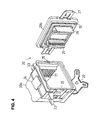
- the seal member 10 is used in a substrate storage container 20 shown in Fig. 4.
- the substrate storage container 20 is constituted by a container body 20a having an opening on its front side and a lid or cover 20b which closes the opening.
- the container body 20a is provided on opposed inner walls thereof at equal intervals in a vertical direction with supporting shelves 21 which are protruded inwardly in a manner to be opposed to each other so as to support substrates in a horizontal orientation.
- the container body 20a has a bottom plate 22 for positioning the container body 20a with respect to an apparatus mounted on a bottom thereof.
- the container body 20a also has handle members 23 for manual conveyance and a robotic flange 24 for automatic conveyance which are respectively mounted on sides and a top thereof, as required.
- at least one pair of cover engaging portions 25 for engaging the cover 20b are provided at a periphery of the opening of the container body 20a.
- the seal member 10 formed in the endless shape is mounted on a side wall of the cover 20b in order to hermetically close the opening along its entire periphery.
- a pair of retainers 26 formed therein with V grooves which are adapted to abut on respective substrates are mounted on an inner surface of the cover 20b opposing the opening of the container body 20a in a manner to project towards an interior of the container body 20a so that the retainers 26 abut on end portions of the substrates received in the container body 20a.
- the cover 20b has a pair of engaging members 27 mounted on the opposite sides of the side wall thereof so as to hold the cover 20b on the container body 20a.
- the container body 20a and the cover 20b are each formed to be a transparent body or an opaque body using thermoplastic resin such as polycarbonate resin, polybutylene terephthalate resin or the like. Also, the resin may be antistatic or conductive thermoplastic resin in which an antistatic agent or a conductive agent has been added.
- thermoplastic resin such as polycarbonate resin, polybutylene terephthalate resin or the like.
- the resin may be antistatic or conductive thermoplastic resin in which an antistatic agent or a conductive agent has been added.
- the shape of the seal member 10 is not particularly limited to a specific one.
- the seal member can have any shape corresponding to the opening of the container body 20a, for example, the general shape thereof may be circular or oval.
- the sectional shape of the seal member 10 is formed in, for example, an inverted T-shape as shown in Fig. 2, where one end thereof is formed in a semicircular shape so as to serve as a seal forming portion adapted to come in elastically deformable contact with the opening end portion of the container body and the other end thereof is formed over its entire periphery with an engaging groove 13 serving as an engaging portion when the seal member is attached to the cover 20b.
- the cover 20b is provided on the side wall thereof with an engaging projection 28 which serves as a fitting portion with respect to the seal member and which is fitted into the engaging groove 13 of the seal member. Attaching of the seal member 10 is performed by pushing the seal member 10 into a seal member receiving groove 16 provided in the side face of the cover 20b and fitting the engaging groove 13 and the engaging projection 28 to each other.
- the seal member 10 is not limited to being attached to the cover 20b. Instead, the seal member 10 can be attached to the peripheral edge of the opening of the container body 20a to cause the distal end of the seal member 10 to abut on the cover 20b.
- the engaging portion may be formed in a projection-like shape instead of the above-described groove shape or hole shape, and the fitting portion may be formed in any shape fittingly engageable with the engaging portion, such as a groove or a hole instead of the above-described projection.
- the seal member 10 may be formed to have an h-shape, an I-shape or the like in section instead of the inverted T-shape shown in Fig. 2.
- the base body section 11 may be formed in any shape similar to the general shape of the covering section 12 but in a reduced size insofar as that the compression performance of the covering section 12 is not affected.
- the base body section 11 is formed of a rigid first material selected from the group of thermoplastic resin such as polypropylene, polyethylene, polyethylene terephthalate, polycarbonate, polybutylene terephthalate, polystyrene and the like, thermosetting resin such as phenol resin, epoxy resin and the like, metal materials such as iron, stainless steel, aluminum and the like, ceramics and the like.
- the covering section 12 is formed of a flexible and elastic second material selected from the group of various thermoplastic elastomers such as polyolefine rubber, polyester rubber, polystyrene rubber, polyurethane rubber, fluororubber, and rubber materials such as EPDM, NBR, IR and the like. Taking into account efficiency in integration of two such different kinds of materials, it is preferable that the thermoplastic resin material be selected as the first material and the thermoplastic elastomer be selected as the second material.
- thermoplastic polyolefine elastomer a soft component of which is EPDM or ethylene-propylene-diene terpolymer, and a hard component of which is polypropylene, wherein these components are mixed and a portion or all of the mixture is cross-linked
- polypropylene or polyethylene be selected as the material for the base body section 11
- thermoplastic polyester elastomer a soft component of which is an aliphatic polyether copolymer or aliphatic polyester and a hard component of which comprises aromatic polyester resin
- polycarbonate, polyethylene terephthalate or polybutylene terephthalate be selected for the base body section 11.
- the seal member 10 can be obtained by first forming the base body section 11 using the above-described thermoplastic resin material, then inserting and holding the obtained base body section 11 in a mold for molding the covering section 12, and thereafter filling a thermoplastic elastomer in the remaining space, to thereby integrate the elastomer with the base body section 11.
- the base body section 11 be held in a cavity of the mold utilizing fixed or movable holding pins or the like according to a two-color molding or insert molding technique which has been conventionally known in the art such that the base body section 11 will not move in the mold.
- a movable pin which can be displaced due to resin pressure be used, so that no undesirable recessed portion which is a mark of the holding pin will be left on a surface of the covering section 12 obtained.
- the covering section 12 of the seal member 10 can be continuously molded by a two color molding machine when the shape of the base body section 11 is specially designed.
- the seal member 10 Since the seal member 10 thus formed has the base body section 11 over the entire periphery thereof, the seal member 10 is rigid and has a shape retention, so that the seal member 10 is not readily deformed as compared with the seal member made only of an elastic material, and thus it is easy to handle. Such a seal member can also be handled even by an automatic machine when cleaning, storing or attaching the seal member.
- the seal member 10 In attaching the seal member 10 to the substrate storage container 20, the seal member 10 has the base body section 11 so that force transmission is excellent, whereby the seal member can be easily engaged with the engaged portion by pushing the seal member at locations thereof spaced at equal intervals without strongly pushing the seal member over the entire periphery thereof.
- the seal member 10 since the seal member 10 has the base body section 11 and thus it is hard to deform, an engaging force in engagement becomes large to make it difficult for the seal member to come off from the engaged portion, so that the seal member is prevented from being displaced during use. It is preferable that the base body section 11 be not extended into a tip end of the projection provided on the covering section 12, which projection forms a seal between the substrate storage container 20 and the covering section 12, so that the tip end of the projection has sufficient flexibility.
- seal member which has a base body section and a covering section like the seal member 10 described above but which has the entire area of the base body section thereof covered with the covering section may be employed.
- the seal member 30 includes a base body section 31 formed of the first material, for example, a thermoplastic resin material, and a covering section 32 formed of the second material, for example, a thermoplastic elastomer.
- the base body section 31 is provided thereon with one or a plurality of tabs 34 extending outward through the covering section 32.
- the tabs 34 integrally provided on the base body section 31 formed of the thermoplastic resin which is rigid can be utilized as portions to be grasped or sucked during handling of the seal member, such as taking out the seal member during molding, subsequent storage thereof, attaching of it to the substrate storage container 20 or the like.
- the plurality of tabs 34 are disposed at corners of the seal member 30, in the middle of the four sides thereof and the like, as shown in Fig. 5, so that at the time the seal member 30 is attached to the substrate storage container 20, a force is transmitted to the other portions via the rigid base body section 31 by pushing the tabs 34 in, resulting in the entire area of the seal member 30 being readily engaged and held in place.
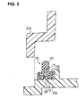
- an engaging means 35 for holding the tab 34 is provided on the cover 20b, as shown in Fig. 7, or a through hole or a notch is formed in a tab 44, as shown in Fig. 9 wherein another example of the seal member of the second embodiment of the present invention in use is illustrated, whereas an engaging means 45 such as a split pin, which fits in the hole or notch to hold the tab 44, is provided on the cover 20b, so that the seal member 30 or 40 can be positively prevented from being unsteadily lifted or spaced from the cover 20b.
- the tabs 34 or 44 being held in this manner, for example, in the embodiment shown in Fig.
- the tabs 34 are arranged only on one side or the inner side of the seal member 30, but it is preferable that the tabs 34 or 44 be provided on the seal member 30 or 40 to be held in such a manner to be protruded alternately inwards and outwards, as shown in Fig. 8.
- a seal member receiving groove 36 shown in Fig. 7 can be omitted, so that an attaching structure of the seal member 30 or 40 can be simplified.
- Reference numerals 33 and 43 denote engaging grooves in the drawings.
- the base body section 44 and the covering section 42 are respectively formed of the first material and the second material described above.
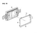
- a seal member 50 of the third embodiment of the present invention is constituted by a base body section 51 formed of the first material and a covering section 52 formed of the second material.
- the base body section 51 is formed to be a rectangular frame made of the first material which is like the material used for the base body section 11 of the seal member 10 in the above described embodiment, for example, a thermoplastic resin.
- An engaging protrusion 53 is formed on an inner peripheral side surface of the base body section 51 so as to be fitted in a fitting portion 61 formed on an inner surface of a cover 60.
- the covering section 52 is formed of the second material which is like the material used for the covering section 12 of the seal member 10 in the above described embodiment, for example, a thermoplastic elastomer.
- the covering section 52 covers a portion of the base body section 51 including the engaging protrusion 53 provided on the inner periphery of the base body section 51 and is fixed or securely mounted to the inner peripheral side surface of the base body section 51.
- portions of the base body section 51 other than the engaging protrusion 53 also be covered with a material similar to the covering section 52 such that the portions of the base body section 51 and the cover 60 do not come into direct contact with each other. Provision of such a covering can prevent portions which are both formed of the thermoplastic resin, such as the base body section 51 and the cover 60, from coming into contact with each other, so that the substrates stored in the substrate storage container can be prevented from being contaminated by powder generated due to rubbing or frictional wear of the thermoplastic resins, which is preferable.
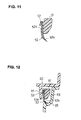
- the covering section 52 comprises a base portion 52a fixed to the base body section 51 and a projecting portion 52b extending downwards from the base portion 52a in Fig. 11.
- the projecting portion 52b is formed to become gradually thinner towards a tip end thereof in Fig. 11.
- the projecting portion 52b is formed so as to extend in a curved manner or in a linear manner obliquely, and the projecting portion 52b pressingly comes in contact with an opening portion of a container body 65 with an appropriate force, as shown in Fig. 12, to thereby hermetically seal the opening portion of the container body 65.
- the projecting portion 52b may be formed to have various shapes other than that described above, for example, the projecting portion 52b may be formed to have an I-shape such that a distal end thereof is located on an extension line of the base portion 52a in Fig. 12, or the projecting portion 52b may be formed to have an L-shape such that it comes in contact with a side wall 66 of the opening portion of the container body 65. Also, a place where the covering section 52 is disposed is not limited to the inner periphery of the base body section 51. Instead, it may be located at an outer periphery or the other portion, as required.
- a seal member is rigid and is hard to deform, so that the seal member is easy to handle after being molded and easy to mount to a substrate storage container, and the seal member is not lifted during use to thereby prevent the seal member from being displaced.
- Such a seal member allows automatic mounting of the seal member to a substrate storage container using the same.
Landscapes
- Engineering & Computer Science (AREA)
- General Engineering & Computer Science (AREA)
- Mechanical Engineering (AREA)
- Physics & Mathematics (AREA)
- Geometry (AREA)
- Container, Conveyance, Adherence, Positioning, Of Wafer (AREA)
- Packaging Frangible Articles (AREA)
- Closures For Containers (AREA)
Abstract
Description
Claims (6)
- A seal member interposed between an opening end portion of a substrate storage container and a cover, which container is comprised of a container body which has said opening end portion and which stores a substrate and said cover, characterized in that:said seal member comprises a base body section formed of a first material and a covering section formed of a second material and covering at least a part of said base body section; andsaid covering section includes a seal forming portion which comes in contact with one of said container body and said cover to form a seal.
- A seal member according to claim 1, characterized in that said first material comprises a thermoplastic resin material and said second material comprises a thermoplastic elastomer.
- A seal member according to claim 1 or 2, characterized in that said covering section is one which covers the entire area of said base body section.
- A seal member according to claim 1 or 2, characterized in that said base body section includes a portion which forms a tab projecting from said covering section.
- A seal member according to claim 1 or 2, characterized in that said covering section is formed on an outer peripheral surface or an inner peripheral surface of said base body section; and
said covering section is provided with a curved projecting portion formed at one end thereof, which projecting portion serves as said seal forming portion, and is provided with an engaging portion formed at the other end thereof, which engaging portion is engageable with the other one of said container body and said cover. - A substrate storage container comprising a container body which has an opening end portion and stores a substrate and a cover, wherein a seal member is interposed between said opening end portion and said cover, characterized in that:said seal member comprises a base body section which is formed of a first material and a covering section which is formed of a second material and covers at least a part of said base body section;said covering section is provided at one end thereof with a seal forming portion which comes in contact with one of said container body and said cover to form a seal and is provided at the other end thereof with an engaging portion which is engageable with the other one of said container body and said cover; anda fitting portion which retains said engaging portion is formed on the other one of said container body and said cover.
Applications Claiming Priority (3)
| Application Number | Priority Date | Filing Date | Title |
|---|---|---|---|
| JP2000372527 | 2000-12-07 | ||
| JP2000372527 | 2000-12-07 | ||
| PCT/JP2001/010732 WO2002047154A1 (en) | 2000-12-07 | 2001-12-07 | Seal member, and substrate storage container using the seal member |
Publications (3)
| Publication Number | Publication Date |
|---|---|
| EP1341226A1 true EP1341226A1 (en) | 2003-09-03 |
| EP1341226A4 EP1341226A4 (en) | 2006-05-03 |
| EP1341226B1 EP1341226B1 (en) | 2013-06-12 |
Family
ID=18842061
Family Applications (1)
| Application Number | Title | Priority Date | Filing Date |
|---|---|---|---|
| EP01999972.1A Expired - Lifetime EP1341226B1 (en) | 2000-12-07 | 2001-12-07 | Seal member, and substrate storage container using the seal member |
Country Status (7)
| Country | Link |
|---|---|
| US (1) | US7029013B2 (en) |
| EP (1) | EP1341226B1 (en) |
| JP (1) | JP4173000B2 (en) |
| KR (1) | KR101257950B1 (en) |
| CN (1) | CN1246894C (en) |
| TW (1) | TWI259501B (en) |
| WO (1) | WO2002047154A1 (en) |
Cited By (1)
| Publication number | Priority date | Publication date | Assignee | Title |
|---|---|---|---|---|
| DE10349921B4 (en) * | 2003-10-25 | 2017-03-09 | Carl Freudenberg Kg | poetry |
Families Citing this family (56)
| Publication number | Priority date | Publication date | Assignee | Title |
|---|---|---|---|---|
| US7463338B2 (en) * | 2003-07-08 | 2008-12-09 | Hoya Corporation | Container for housing a mask blank, method of housing a mask blank, and mask blank package |
| US7578407B2 (en) * | 2004-04-18 | 2009-08-25 | Entegris, Inc. | Wafer container with sealable door |
| US20060065571A1 (en) * | 2004-09-27 | 2006-03-30 | Tim Hsiao | Wafer shipping box and wafer transportation method |
| US20080257779A1 (en) * | 2004-09-29 | 2008-10-23 | Hoya Corporation | Supporting Member For Thin-Film-Coated Boards, Storage Container For Thin-Film-Coated Boards, Mask-Blank-Storing Body, Transfer-Mask-Storing Body, and Method For Transporting Thin-Film-Coated Boards |
| JP4634772B2 (en) * | 2004-10-14 | 2011-02-16 | ミライアル株式会社 | Storage container |
| JP4354901B2 (en) * | 2004-12-15 | 2009-10-28 | 株式会社東海理化電機製作所 | Engagement structure |
| JP2006236671A (en) * | 2005-02-23 | 2006-09-07 | Nitto Shinko Kk | Seal material for solid polymer fuel cell |
| EP1873427A1 (en) * | 2005-04-22 | 2008-01-02 | NOK Corporation | Gasket |
| JP5473192B2 (en) * | 2006-01-25 | 2014-04-16 | 株式会社豊田自動織機 | Electric compressor |
| JP4925164B2 (en) * | 2006-01-31 | 2012-04-25 | 株式会社吉野工業所 | Airtight container with lid |
| KR20090023567A (en) * | 2006-05-29 | 2009-03-05 | 신에츠 폴리머 가부시키가이샤 | Board Storage Container |
| US20100052260A1 (en) * | 2007-03-07 | 2010-03-04 | Siemens Aktiengesellscahft | Device and method for producing a seal |
| CA123750S (en) * | 2007-06-15 | 2008-10-21 | Sandvik Intellectual Property | Seal |
| DE102007030883A1 (en) * | 2007-07-03 | 2009-01-08 | Schaeffler Kg | Seal for a hydrostatic linear guide |
| US7828302B2 (en) * | 2007-08-15 | 2010-11-09 | Federal-Mogul Corporation | Lateral sealing gasket and method |
| US7770692B2 (en) * | 2007-09-14 | 2010-08-10 | Gm Global Technology Operations, Inc. | Engine acoustic treatment |
| JP4980252B2 (en) * | 2008-01-15 | 2012-07-18 | 信越ポリマー株式会社 | Substrate storage container and method of attaching seal gasket thereof |
| JP4401417B2 (en) * | 2008-04-01 | 2010-01-20 | 株式会社山田製作所 | Packing material mounting structure |
| TWI341816B (en) * | 2008-08-14 | 2011-05-11 | Gudeng Prec Industral Co Ltd | A wafer container having the latch and inflatable seal element |
| JP5198335B2 (en) * | 2008-08-27 | 2013-05-15 | 日本メクトロン株式会社 | Seal structure of electronic equipment |
| TW201010916A (en) * | 2008-09-12 | 2010-03-16 | Gudeng Prec Industral Co Ltd | Wafer container with roller |
| JP5268142B2 (en) * | 2008-09-27 | 2013-08-21 | Hoya株式会社 | Mask blank storage case, mask blank storage method, and mask blank storage body |
| TWI485796B (en) * | 2008-11-21 | 2015-05-21 | 家登精密工業股份有限公司 | Container for accommodating thin plates |
| NZ583590A (en) * | 2009-02-27 | 2011-09-30 | Clipsal Australia Pty Ltd | An electrical enclosure and a gasket with a hard stop for an electrical enclosure |
| US9010718B2 (en) * | 2009-08-10 | 2015-04-21 | Dean Foote | Seal assembly for a pressure plate in a blowout preventer |
| JP2011100983A (en) * | 2009-10-07 | 2011-05-19 | Shin Etsu Polymer Co Ltd | Wafer storage container |
| US20170236737A1 (en) * | 2010-10-20 | 2017-08-17 | Entegris, Inc. | Wafer container with door guide and seal |
| JP6114193B2 (en) * | 2010-10-20 | 2017-04-12 | インテグリス・インコーポレーテッド | Wafer container with door guide and seal |
| KR101851741B1 (en) * | 2010-10-26 | 2018-04-24 | 엔오케이 가부시키가이샤 | Gasket |
| JP2012255381A (en) * | 2011-06-09 | 2012-12-27 | Mitsubishi Heavy Ind Ltd | Electric compressor |
| KR101309213B1 (en) * | 2011-06-28 | 2013-09-23 | 주식회사 삼에스코리아 | Wafer carrier |
| US9108776B2 (en) * | 2012-03-09 | 2015-08-18 | Wki Holding Company, Inc. | Lid, and container system and lid |
| JP2015521377A (en) | 2012-05-04 | 2015-07-27 | インテグリス・インコーポレーテッド | Wafer container with door contact seal |
| KR20150037928A (en) * | 2012-07-30 | 2015-04-08 | 이턴 코포레이션 | Redundant lip seal for valve |
| JP6056343B2 (en) * | 2012-10-03 | 2017-01-11 | Nok株式会社 | Sealing structure |
| JP6249557B2 (en) * | 2012-12-19 | 2017-12-20 | 株式会社堀場エステック | Seal member and method for manufacturing seal member |
| JP6119287B2 (en) * | 2013-02-14 | 2017-04-26 | 株式会社Sumco | Buffer material for packing wafer storage containers |
| JP2014183102A (en) * | 2013-03-18 | 2014-09-29 | Fujitsu Ltd | Electronic apparatus |
| JP2015014343A (en) * | 2013-07-08 | 2015-01-22 | 株式会社デンソー | Seal structure |
| WO2015025410A1 (en) * | 2013-08-22 | 2015-02-26 | ミライアル株式会社 | Substrate storing container |
| US9494236B2 (en) | 2013-11-06 | 2016-11-15 | Dana Automotive Systems Group, Llc | Gasket with dissimilar materials |
| WO2015069829A1 (en) * | 2013-11-06 | 2015-05-14 | Dana Automotive Systems Group, Llc | Gasket with dissimilar materials |
| CN104265901B (en) * | 2014-08-18 | 2016-08-24 | 常熟市董浜镇徐市盛峰液压配件厂 | Enclosure seal circle |
| CN104944042A (en) * | 2015-05-11 | 2015-09-30 | 张立 | Slide type electrode plate storage rack |
| KR20170076179A (en) * | 2015-12-24 | 2017-07-04 | 삼성전자주식회사 | Wafer container |
| DE102016105047A1 (en) * | 2016-03-18 | 2017-09-21 | Gea Mechanical Equipment Gmbh | Sealing arrangement for sealing a gap |
| WO2018169687A1 (en) * | 2017-03-16 | 2018-09-20 | ASSA ABLOY Residential Group, Inc. | Gasket system for an electromechanical lock |
| JP7073599B2 (en) * | 2018-05-28 | 2022-05-24 | 信越ポリマー株式会社 | Board storage container |
| TWI674225B (en) * | 2018-07-31 | 2019-10-11 | 中勤實業股份有限公司 | Waterproof breathable assembly having nano-membrane, and substrate cassette and rod structure having waterproof breathable assembly |
| JP7503990B2 (en) * | 2020-10-06 | 2024-06-21 | タイコエレクトロニクスジャパン合同会社 | Seal structure |
| CN116547605A (en) * | 2020-10-13 | 2023-08-04 | 恩特格里斯公司 | Integral seal for a container |
| US11608895B2 (en) * | 2020-10-29 | 2023-03-21 | Aptiv Technologies Limited | Dispensing seal |
| CN115639719B (en) * | 2021-07-19 | 2025-05-27 | 长鑫存储技术有限公司 | Mask box and semiconductor equipment |
| JP7651419B2 (en) * | 2021-09-15 | 2025-03-26 | 信越ポリマー株式会社 | Substrate storage container |
| US12222036B2 (en) * | 2021-10-08 | 2025-02-11 | Hoffman Enclosures, Inc. | Sealing arrangement for an enclosure |
| TWI904751B (en) * | 2024-02-06 | 2025-11-11 | 家登精密工業股份有限公司 | Semiconductor workpiece conveyor box |
Family Cites Families (34)
| Publication number | Priority date | Publication date | Assignee | Title |
|---|---|---|---|---|
| US3230290A (en) * | 1961-02-23 | 1966-01-18 | Shell Oil Co | Composite gasket and method of applying same |
| US3355057A (en) * | 1964-12-31 | 1967-11-28 | Pine Scient Company | Desiccator seal |
| US3578346A (en) * | 1969-01-29 | 1971-05-11 | Parker Hannifin Corp | Sealed joint and gasket therefor |
| US4026565A (en) * | 1975-03-10 | 1977-05-31 | Parker-Hannifin Corporation | Sealed static joint and gasket therefor |
| US4158757A (en) * | 1978-02-15 | 1979-06-19 | Allen-Bradley Company | Enclosure seal |
| US4345739A (en) * | 1980-08-07 | 1982-08-24 | Barton Valve Company | Flanged sealing ring |
| FR2541410B1 (en) * | 1983-02-23 | 1987-11-13 | Vibrachoc Sa | SEAL FOR AIRCRAFT ELECTRONICS |
| DE3344734A1 (en) * | 1983-12-10 | 1985-06-20 | Kaco Gmbh + Co, 7100 Heilbronn | Sealing element for gaskets |
| US4597583A (en) * | 1985-07-08 | 1986-07-01 | Felt Products Mfg. Co. | Gasket assembly for sealing covers to automotive engines |
| EP0273226B1 (en) * | 1986-12-22 | 1992-01-15 | Siemens Aktiengesellschaft | Transporting container with an interchangeable two-part inner container |
| US4854476A (en) * | 1988-07-25 | 1989-08-08 | Serco Mold, Inc. | Container and perimeter seal therefor |
| US5011162A (en) * | 1989-07-20 | 1991-04-30 | Parker Hannifin Corporation | Bi-lobed sealing element and retainer |
| US5050764A (en) * | 1990-03-08 | 1991-09-24 | Pacesetter Infusion, Ltd. | Lateral compression sealing system and method of making seal |
| DE4109951C2 (en) * | 1991-03-26 | 1993-12-23 | Reinz Dichtungs Gmbh | Sheet metal elastomer flat gasket |
| US5145190A (en) * | 1991-03-27 | 1992-09-08 | Freudenberg-Nok | Gasket assembly |
| JPH04307181A (en) * | 1991-04-04 | 1992-10-29 | Sanshin Ind Co Ltd | Seal structure |
| US5469963A (en) * | 1992-04-08 | 1995-11-28 | Asyst Technologies, Inc. | Sealable transportable container having improved liner |
| JPH06201048A (en) * | 1993-01-04 | 1994-07-19 | Three Bond Co Ltd | Assembly seal material and assembly method thereof |
| US5564714A (en) * | 1993-02-23 | 1996-10-15 | Three Bond Co., Ltd. | Rubber-like molded product with support frame |
| JP2946450B2 (en) * | 1993-04-27 | 1999-09-06 | コマツ電子金属株式会社 | Semiconductor wafer packaging container |
| US5375569A (en) * | 1994-01-26 | 1994-12-27 | General Electric Company | Multi polymer structures for internal combustion engines |
| JP3282121B2 (en) * | 1994-09-20 | 2002-05-13 | 矢崎総業株式会社 | Structure for holding O-rings for sealing of connectors directly attached to equipment |
| WO1996011496A2 (en) * | 1994-10-11 | 1996-04-18 | Empak, Inc. | Container having a cleanable, re-usable box door liner |
| US5536018A (en) * | 1994-11-14 | 1996-07-16 | Fel-Pro Incorporated | Flexible spaghetti gasket seal with stiffening member |
| US5671927A (en) * | 1995-04-07 | 1997-09-30 | Dana Corporation | Gasket assembly with sealing member having main body with integral tabs |
| JP2961068B2 (en) * | 1995-04-13 | 1999-10-12 | ブリヂストン化成品東京株式会社 | Gasket material |
| US5687975A (en) * | 1996-08-21 | 1997-11-18 | Fel-Pro Incorporated | Sealing assembly employing oppositely directed wedges and complementary recesses |
| JP4006041B2 (en) * | 1996-12-27 | 2007-11-14 | 株式会社ヴァンテック | Semiconductor wafer packaging container |
| DE19745348A1 (en) * | 1997-10-14 | 1999-04-15 | Mann & Hummel Filter | Seal for automotive carburetor air intake applied by vulcanization or spray |
| US6354601B1 (en) * | 1999-01-06 | 2002-03-12 | Fluoroware, Inc. | Seal for wafer containers |
| JP3749802B2 (en) * | 1999-03-16 | 2006-03-01 | 内山工業株式会社 | Cover gasket |
| EP1045174A3 (en) * | 1999-04-13 | 2002-10-16 | Bridgestone Corporation | Gasket fitted to frame and process for producing the same |
| JP2001002180A (en) * | 1999-06-17 | 2001-01-09 | Sony Corp | Substrate transport container |
| US6364152B1 (en) * | 2000-04-12 | 2002-04-02 | Dart Industries Inc. | Food storage container |
-
2001
- 2001-12-05 TW TW090130059A patent/TWI259501B/en not_active IP Right Cessation
- 2001-12-07 CN CNB018046622A patent/CN1246894C/en not_active Expired - Fee Related
- 2001-12-07 WO PCT/JP2001/010732 patent/WO2002047154A1/en not_active Ceased
- 2001-12-07 US US10/204,295 patent/US7029013B2/en not_active Expired - Fee Related
- 2001-12-07 JP JP2002548774A patent/JP4173000B2/en not_active Expired - Fee Related
- 2001-12-07 EP EP01999972.1A patent/EP1341226B1/en not_active Expired - Lifetime
- 2001-12-07 KR KR1020027010120A patent/KR101257950B1/en not_active Expired - Fee Related
Cited By (1)
| Publication number | Priority date | Publication date | Assignee | Title |
|---|---|---|---|---|
| DE10349921B4 (en) * | 2003-10-25 | 2017-03-09 | Carl Freudenberg Kg | poetry |
Also Published As
| Publication number | Publication date |
|---|---|
| WO2002047154A1 (en) | 2002-06-13 |
| CN1398427A (en) | 2003-02-19 |
| JPWO2002047154A1 (en) | 2004-04-08 |
| US20030107187A1 (en) | 2003-06-12 |
| JP4173000B2 (en) | 2008-10-29 |
| KR20020076286A (en) | 2002-10-09 |
| CN1246894C (en) | 2006-03-22 |
| US7029013B2 (en) | 2006-04-18 |
| EP1341226B1 (en) | 2013-06-12 |
| KR101257950B1 (en) | 2013-04-24 |
| TWI259501B (en) | 2006-08-01 |
| EP1341226A4 (en) | 2006-05-03 |
Similar Documents
| Publication | Publication Date | Title |
|---|---|---|
| US7029013B2 (en) | Seal member, and substrate storage container using the same | |
| KR100904799B1 (en) | Hermetic container | |
| KR101008867B1 (en) | Board Storage Container | |
| KR101472145B1 (en) | Substrate storage container | |
| JP3838786B2 (en) | Precision substrate storage container, positioning structure thereof, and positioning method of precision substrate storage container | |
| KR101008866B1 (en) | Storage container | |
| KR20010007019A (en) | Identification structure of a substrate storage container and method of identifying a substrate storage container | |
| KR19990029386A (en) | Transport container | |
| JP4133407B2 (en) | Thin plate storage container | |
| US5586658A (en) | Wafer cushions for wafer shipper | |
| US20040020930A1 (en) | Cover body for sheet supporting container and sheet supporting container | |
| US20050133402A1 (en) | Lid unit for thin-plate supporting container | |
| JPH0945759A (en) | package | |
| US20060213796A1 (en) | Airtight container | |
| KR102113139B1 (en) | Substrate storage container | |
| KR20020025027A (en) | Storage container for precision substrates | |
| CN119133041A (en) | Buffer holder for substrate container | |
| JP2005256958A (en) | Seal member | |
| JP2004342844A (en) | Precision substrate storage container | |
| JP4181926B2 (en) | Substrate storage container | |
| KR20060129946A (en) | Lamination support container | |
| KR20250042833A (en) | A set comprising a microplate, a lid, and a device for releasing the snap connection between the microplate and the lid | |
| US20060138143A1 (en) | Lid unit for thin-plate supporting container and method for attaching lid unit | |
| JP7662561B2 (en) | Filter removal tool for substrate storage container and method of using same | |
| JPH1064991A (en) | Semiconductor wafer storage container |
Legal Events
| Date | Code | Title | Description |
|---|---|---|---|
| PUAI | Public reference made under article 153(3) epc to a published international application that has entered the european phase |
Free format text: ORIGINAL CODE: 0009012 |
|
| 17P | Request for examination filed |
Effective date: 20030620 |
|
| AK | Designated contracting states |
Kind code of ref document: A1 Designated state(s): AT BE CH CY DE DK ES FI FR GB GR IE IT LI LU MC NL PT SE TR |
|
| AX | Request for extension of the european patent |
Extension state: AL LT LV MK RO SI |
|
| A4 | Supplementary search report drawn up and despatched |
Effective date: 20060317 |
|
| 17Q | First examination report despatched |
Effective date: 20070216 |
|
| RAP1 | Party data changed (applicant data changed or rights of an application transferred) |
Owner name: SHIN-ETSU HANDOTAI CO., LTD. Owner name: SHIN-ETSU POLYMER CO., LTD. |
|
| GRAP | Despatch of communication of intention to grant a patent |
Free format text: ORIGINAL CODE: EPIDOSNIGR1 |
|
| RBV | Designated contracting states (corrected) |
Designated state(s): DE FR GB IT |
|
| GRAS | Grant fee paid |
Free format text: ORIGINAL CODE: EPIDOSNIGR3 |
|
| GRAA | (expected) grant |
Free format text: ORIGINAL CODE: 0009210 |
|
| RBV | Designated contracting states (corrected) |
Designated state(s): DE FR GB IT |
|
| RAP1 | Party data changed (applicant data changed or rights of an application transferred) |
Owner name: SHIN-ETSU POLYMER CO. LTD. |
|
| AK | Designated contracting states |
Kind code of ref document: B1 Designated state(s): DE FR GB IT |
|
| REG | Reference to a national code |
Ref country code: GB Ref legal event code: FG4D |
|
| REG | Reference to a national code |
Ref country code: DE Ref legal event code: R096 Ref document number: 60148075 Country of ref document: DE Effective date: 20130808 |
|
| PLBE | No opposition filed within time limit |
Free format text: ORIGINAL CODE: 0009261 |
|
| STAA | Information on the status of an ep patent application or granted ep patent |
Free format text: STATUS: NO OPPOSITION FILED WITHIN TIME LIMIT |
|
| 26N | No opposition filed |
Effective date: 20140313 |
|
| PG25 | Lapsed in a contracting state [announced via postgrant information from national office to epo] |
Ref country code: IT Free format text: LAPSE BECAUSE OF FAILURE TO SUBMIT A TRANSLATION OF THE DESCRIPTION OR TO PAY THE FEE WITHIN THE PRESCRIBED TIME-LIMIT Effective date: 20130612 |
|
| REG | Reference to a national code |
Ref country code: DE Ref legal event code: R097 Ref document number: 60148075 Country of ref document: DE Effective date: 20140313 |
|
| GBPC | Gb: european patent ceased through non-payment of renewal fee |
Effective date: 20131207 |
|
| PG25 | Lapsed in a contracting state [announced via postgrant information from national office to epo] |
Ref country code: GB Free format text: LAPSE BECAUSE OF NON-PAYMENT OF DUE FEES Effective date: 20131207 |
|
| PGFP | Annual fee paid to national office [announced via postgrant information from national office to epo] |
Ref country code: FR Payment date: 20141208 Year of fee payment: 14 |
|
| REG | Reference to a national code |
Ref country code: DE Ref legal event code: R082 Ref document number: 60148075 Country of ref document: DE Representative=s name: PATENTANWAELTE WEICKMANN & WEICKMANN, DE Ref country code: DE Ref legal event code: R082 Ref document number: 60148075 Country of ref document: DE Representative=s name: WEICKMANN & WEICKMANN PATENTANWAELTE - RECHTSA, DE Ref country code: DE Ref legal event code: R082 Ref document number: 60148075 Country of ref document: DE Representative=s name: WEICKMANN & WEICKMANN PATENT- UND RECHTSANWAEL, DE |
|
| REG | Reference to a national code |
Ref country code: FR Ref legal event code: ST Effective date: 20160831 |
|
| PG25 | Lapsed in a contracting state [announced via postgrant information from national office to epo] |
Ref country code: FR Free format text: LAPSE BECAUSE OF NON-PAYMENT OF DUE FEES Effective date: 20151231 |
|
| PGFP | Annual fee paid to national office [announced via postgrant information from national office to epo] |
Ref country code: DE Payment date: 20161129 Year of fee payment: 16 |
|
| REG | Reference to a national code |
Ref country code: DE Ref legal event code: R119 Ref document number: 60148075 Country of ref document: DE |
|
| PG25 | Lapsed in a contracting state [announced via postgrant information from national office to epo] |
Ref country code: DE Free format text: LAPSE BECAUSE OF NON-PAYMENT OF DUE FEES Effective date: 20180703 |