EP1340909B1 - Zündendstufe - Google Patents
Zündendstufe Download PDFInfo
- Publication number
- EP1340909B1 EP1340909B1 EP03002052A EP03002052A EP1340909B1 EP 1340909 B1 EP1340909 B1 EP 1340909B1 EP 03002052 A EP03002052 A EP 03002052A EP 03002052 A EP03002052 A EP 03002052A EP 1340909 B1 EP1340909 B1 EP 1340909B1
- Authority
- EP
- European Patent Office
- Prior art keywords
- ignition
- control unit
- output stage
- ignition output
- potential
- Prior art date
- Legal status (The legal status is an assumption and is not a legal conclusion. Google has not performed a legal analysis and makes no representation as to the accuracy of the status listed.)
- Expired - Lifetime
Links
Images

Classifications
-
- F—MECHANICAL ENGINEERING; LIGHTING; HEATING; WEAPONS; BLASTING
- F02—COMBUSTION ENGINES; HOT-GAS OR COMBUSTION-PRODUCT ENGINE PLANTS
- F02P—IGNITION, OTHER THAN COMPRESSION IGNITION, FOR INTERNAL-COMBUSTION ENGINES; TESTING OF IGNITION TIMING IN COMPRESSION-IGNITION ENGINES
- F02P3/00—Other installations
- F02P3/02—Other installations having inductive energy storage, e.g. arrangements of induction coils
- F02P3/04—Layout of circuits
- F02P3/055—Layout of circuits with protective means to prevent damage to the circuit, e.g. semiconductor devices or the ignition coil
- F02P3/0552—Opening or closing the primary coil circuit with semiconductor devices
Definitions
- the present invention relates to an ignition output, which can be reliably and safely controlled by an engine control unit.
- the US-A-5,131,377 describes an ignition device for internal combustion engines, wherein an electrical signal is converted by a control unit into an optical signal which is used to drive a phototransistor for controlling a primary current of an ignition coil.
- FIG. 3 is an example of a control of an ignition module with a Zündendh according to the prior art represented by an engine control unit.
- FIG. 1 an engine control unit 1 is shown, which is connected to a positive supply voltage Vcc1 and to a negative supply voltage VGND1 in the form of the body ground of a corresponding motor vehicle.
- the engine control unit 1 is connected via a wiring harness 2, which according to FIG. 3 is shown in the form of corresponding harness resistors, connected to the controlled ignition module 3.
- the ignition module 3 comprises an input resistor 5, which, as in FIG FIG. 3 shown coupled with a drive or control circuit with Standstill Shutdown 6 for driving a fuze 7.
- the igniter 7 is in turn connected to the primary winding of a transformer 8 which is connected to a positive supply voltage Vcc2 and whose secondary winding generates the desired ignition voltage for a spark plug (not shown) of the respective motor vehicle.
- the secondary winding of the transformer 8 is connected to a negative supply voltage terminal VGND2 in the form of the motor ground.
- the present invention is therefore based on the object to provide an ignition output, which can be reliably and safely controlled and turned on and off.
- the ignition output stage comprises coupling means which enable a potential-free coupling between a control device provided for controlling the ignition output stage or the igniter contained therein.
- the control electronics is independent of potential shifts between the respective engine and the control unit; Potential shifts occurring at the ignition output stage are uncritical due to the thus ensured final coupling.
- the system can be made more robust, and it is a safe switching on and off of the (external) ignition power with increased fault tolerance of the ignition system possible. It is also particularly advantageous that the previously used engine control units without modification can continue to be used for operation with the ignition output stage according to the invention.
- the design of the potential-free coupling agent according to the invention is in principle not limited.
- the coupling means according to the invention need only be such that a mass offset or potential shifts between the control unit and the ignition output stage does not adversely affect the function of the ignition system.
- the coupling means may be such that they bring about a galvanic decoupling between the control unit and the ignition output stage, which is possible for example by the use of an optocoupler.
- the coupling means need not necessarily bring about a galvanic decoupling between the control unit and the ignition output, but for the potential-free coupling between the control unit and the ignition output, for example, a differential amplifier can be used, which detects the falling at an input resistor connected to the control unit voltage and in the corresponding control voltage for the igniter of the ignition power converts.
- the coupling means according to the invention comprise for the potential-free coupling between the control unit and the ignition output a coupling element which output side (at least indirectly) with the igniter of the ignition output stage and a negative supply voltage or ground terminal (motor ground) is coupled.
- the coupling element On the input side, however, the coupling element is coupled to the control unit and a negative supply voltage or ground connection of the control unit (body ground). This ensures that the primary current flowing through the primary winding of the transformer connected to the igniter of the ignition output stage no longer flows through the ground terminal of the control unit, that is, the "signal ground”.
- Potential shifts in the ignition module or in the ignition output stage are not critical due to this potential-free decoupling; the power loss in the igniter of the ignition output can be further minimized.
- FIG. 1 and FIG. 2 are those components shown which in FIG. 3 shown components, with the same reference numerals, so that a repeated description of these components is omitted and instead to the description above FIG. 3 can be referenced. In the following, therefore, the differences between the in FIG. 1 respectively.
- FIG. 2 illustrated embodiments and in FIG. 3 shown known ignition output.
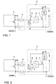
- the ignition module 3 with the ignition output is not connected directly to the engine control unit 1 via the wiring harness 2, but the coupling between the ignition output and the wiring harness 2 and the engine control unit 1 via coupling means 4, which are designed such that a potential-free coupling between enable the engine control unit 1 and the ignition output or the ignition module 3.
- This potential-free coupling takes place through the use of an optocoupler, which on the input side via the wiring harness 2 with the engine control unit 1 and the ground terminal VGND1 (body ground) of the Engine control unit 1 is connected.
- the optocoupler On the output side, the optocoupler is connected on the one hand to the drive or control circuit 6 with standstill shutdown functionality and the resistor 5 and on the other hand to the igniter 7 and the ground terminal VGND2 (motor ground) of the ignition output.
- the primary current flowing via the primary winding of the transformer 8 thus no longer flows via the ground terminal VGND1 of the engine control unit 1.
- Potential shifts at the ignition module 3 are uncritical due to this potential decoupling between the ignition module 3 and the engine control unit 1 for safe switching on and off of the ignition output stage.
- FIG. 2 At the in FIG. 2 embodiment shown is used instead of in FIG. 1 shown optocoupler for potential-free coupling of the ignition module 3 with the engine control unit 1, an input resistor used in combination with a differential amplifier.
- the input resistance is connected to the engine control unit 1 or the corresponding ground terminal VGND1 (body ground).
- the differential amplifier is connected with its two input terminals to the two ends of this input resistor and thus detects the voltage dropping across this input resistor, that is to say the control voltage of the engine control unit 1 for the ignition output stage.
- the differential amplifier On the output side, the differential amplifier is as in FIG. 2 shown connected on the one hand with the resistor 5 and the drive or control circuit 6 with standstill shutdown functionality and on the other hand with the igniter 7 and the ground terminal VGND2 (engine ground) of the ignition module 3.
- the design of the coupling means 4 for effecting a potential-free coupling between the engine control unit 1 and the ignition module 3 or the ignition output stage contained therein is of course not on in FIG. 1 and FIG. 2
- all known to those skilled switching means or components are used, which allow a potential-free coupling between the ignition module 3 and the ignition output and the engine control unit 1, so that potential shifts at the ignition module 3 or a mass offset between the Engine control unit 1 and the ignition module 3 does not adversely affect the reliability of the ignition system.
Landscapes
- Engineering & Computer Science (AREA)
- Chemical & Material Sciences (AREA)
- Combustion & Propulsion (AREA)
- Mechanical Engineering (AREA)
- General Engineering & Computer Science (AREA)
- Ignition Installations For Internal Combustion Engines (AREA)
- Combustion Methods Of Internal-Combustion Engines (AREA)
Description
- Die vorliegende Erfindung betrifft eine Zündendstufe, welche sich durch ein Motorsteuergerät zuverlässig und sicher ansteuern lässt.
- Die
US-A-5 131 377 beschreibt eine Zündvorrichtung für Verbrennungsmotoren, wobei ein elektrisches Signal von einer Steuereinheit in ein optisches Signal gewandelt wird, welches zur Ansteuerung eines Phototransistors zur Steuerung eines Primärstroms einer Zündspule benutzt wird. - In
Figur 3 ist ein Beispiel für eine Ansteuerung eines Zündmoduls mit einer Zündendstufe gemäß dem Stand der Technik durch ein Motorsteuergerät dargestellt. - Dabei ist in
Figur 1 ein Motorsteuergerät 1 gezeigt, welches an eine positive Versorgungsspannung Vcc1 und an eine negative Versorgungsspannung VGND1 in Form der Karosseriemasse eines entsprechenden Kraftfahrzeugs angeschlossen ist. Das Motorsteuergerät 1 ist über einen Kabelbaum 2, welcher gemäßFigur 3 in Form entsprechender Kabelbaumwiderstände dargestellt ist, an das anzusteuernde Zündmodul 3 angeschlossen. Das Zündmodul 3 umfasst einen Eingangswiderstand 5, welcher wie inFigur 3 gezeigt mit einer Ansteuer- bzw. Regelschaltung mit Stillstandsabschaltung 6 zur Ansteuerung eines Zünders 7 gekoppelt ist. Der Zünder 7 ist wiederum mit der an eine positive Versorgungsspannung Vcc2 angeschlossenen Primärwicklung eines Übertragers 8 verbunden, dessen Sekundärwicklung die gewünschte Zündspannung für eine (nicht gezeigte) Zündkerze des jeweiligen Kraftfahrzeugs erzeugt. Wie ausFigur 3 ersichtlich ist, ist die Sekundärwicklung des Übertragers 8 an einen negativen Versorgungspannungsanschluss VGND2 in Form der Motormasse angeschlossen. - Durch einen an den Widerständen im Kabelbaum 2 auftretenden Spannungsabfall kann es zu einem Potenzialversatz zwischen dem Motorsteuergerät 1 und dem Zündmodul 3 kommen. Ebenso kann es zu einem derartigen Potenzialversatz durch einen Spannungsabfall an den einzelnen Anschlusspunkten, beispielsweise an den Massebolzen etc., kommen. Ein derartiger Potenzialversatz hat jedoch zur Folge, dass sich der Spannungspegel am Eingang des Zündmoduls, welcher maßgeblich für die Ansteuerung des Zünders 7 ist, verschiebt, so dass ein sicheres Ein- und Ausschalten des Zünders 7 nicht immer gewährleistet ist. Die Folge kann eine Überhitzung des Zünders 7 sowie im Extremfall eine thermische Zerstörung des gesamten Zündmoduls 3 sein.
- Der vorliegenden Erfindung liegt daher die Aufgabe zu Grunde, eine Zündendstufe bereitzustellen, welche sich zuverlässig und sicher ansteuern sowie ein- und ausschalten lässt.
- Diese Aufgabe wird erfindungsgemäß durch eine Zündendstufe mit den Merkmalen des Anspruchs 1 gelöst. Die Unteransprüche definieren jeweils bevorzugte und vorteilhafte Ausführungsformen der vorliegenden Erfindung.
- Die erfindungsgemäße Zündendstufe umfasst Kopplungsmittel, welche eine potenzialfreie Kopplung zwischen einem zur Steuerung der Zündendstufe bzw. des darin enthaltenen Zünders vorgesehenen Steuergeräts ermöglichen. Durch diese potenzialfreie Kopplung zwischen dem Steuergerät und der Zündendstufe wird die Ansteuerelektronik unabhängig von Potenzialverschiebungen zwischen dem jeweiligen Motor und dem Steuergerät; an der Zündendstufe auftretende Potenzialverschiebungen sind aufgrund der somit gewährleisteten Endkopplung unkritisch. Insgesamt kann somit das System robuster ausgestaltet werden, und es ist ein sicheres Ein- bzw. Ausschalten der (externen) Zündendstufe bei erhöhter Fehlertoleranz des Zündsystems möglich. Besonders vorteilhaft ist auch, dass die bisher verwendeten Motorsteuergeräte ohne Änderung weiterhin für den Betrieb mit der erfindungsgemäßen Zündendstufe verwendet werden können.
- Die Ausgestaltung der erfindungsgemäßen potenzialfreien Kopplungsmittel ist im Prinzip nicht beschränkt. Die erfindungsgemäßen Kopplungsmittel müssen lediglich derart beschaffen sein, dass sich ein Masseversatz bzw. Potenzialverschiebungen zwischen dem Steuergerät und der Zündendstufe nicht nachteilig auf die Funktion des Zündsystems auswirken. So können die Kopplungsmittel beispielsweise derart beschaffen sein, dass sie eine galvanische Entkopplung zwischen dem Steuergerät und der Zündendstufe herbeiführen, was beispielsweise durch die Verwendung eines Optokopplers möglich ist. Die Kopplungsmittel müssen jedoch nicht zwingend eine galvanische Entkopplung zwischen dem Steuergerät und der Zündendstufe herbeiführen, sondern zur potenzialfreien Kopplung zwischen dem Steuergerät und der Zündendstufe kann beispielsweise auch ein Differenzverstärker eingesetzt werden, welcher die an einem mit dem Steuergerät verbundenen Eingangswiderstand abfallende Spannung erfasst und in die entsprechende Steuerspannung für den Zünder der Zündendstufe umsetzt.
- Die erfindungsgemäßen Kopplungsmittel umfassen zur potenzialfreien Kopplung zwischen dem Steuergerät und der Zündendstufe ein Kopplungselement, welches ausgangsseitig (zumindest indirekt) mit dem Zünder der Zündendstufe sowie einem negativen Versorgungsspannungs- bzw. Masseanschluss (Motormasse) gekoppelt ist. Eingangsseitig ist das Kopplungselement hingegen mit dem Steuergerät und einem negativen Versorgungsspannungs- bzw. Masseanschluss des Steuergeräts (Karosseriemasse) gekoppelt. Dadurch ist gewährleistet, dass der über die Primärwicklung des mit dem Zünder verbundenen Übertragers der Zündendstufe fließende Primärstrom nicht mehr über den Masseanschluss des Steuergeräts, das heißt die "Signalmasse", fließt. Potenzialverschiebungen im Zündmodul bzw. in der Zündendstufe sind durch diese potenzialfreie Entkopplung unkritisch; die Verlustleistung im Zünder der Zündendstufe kann darüber hinaus minimiert werden.
- Die Erfindung wird nachfolgend näher unter Bezugnahme auf die Zeichnung anhand bevorzugter Ausführungsbeispiele beschrieben.
-
Figur 1 zeigt eine von einem Motorsteuergerät angesteuerte Zündendstufe gemäß einem ersten Ausführungsbeispiel der vorliegenden Erfindung, -
Figur 2 zeigt eine von einem Motorsteuergerät angesteuerte Zündendstufe gemäß einem zweiten Ausführungsbeispiel der vorliegenden Erfindung, -
Figur 3 zeigt eine von einem Motorsteuergerät angesteuerte Zündstufe gemäß dem Stand der Technik. - In
Figur 1 und Figur 2 sind diejenigen dargestellten Komponenten, welche den inFigur 3 gezeigten Komponenten entsprechen, mit denselben Bezugszeichen versehen, so dass auf eine wiederholte Beschreibung dieser Komponenten verzichtet wird und stattdessen auf die obige Beschreibung zuFigur 3 verwiesen werden kann. Nachfolgend wird daher vorwiegend auf die erfindungsgemäßen Unterschiede zwischen den inFigur 1 bzw.Figur 2 dargestellten Ausführungsbeispielen und der inFigur 3 gezeigten bekannten Zündendstufe eingegangen. - Gemäß
Figur 1 ist das Zündmodul 3 mit der Zündendstufe nicht direkt über den Kabelbaum 2 an das Motorsteuergerät 1 angeschlossen, sondern die Kopplung zwischen der Zündendstufe und dem Kabelbaum 2 bzw. dem Motorsteuergerät 1 erfolgt über Kopplungsmittel 4, welche derart ausgestaltet sind, dass sie eine potenzialfreie Kopplung zwischen dem Motorsteuergerät 1 und der Zündendstufe bzw. dem Zündmodul 3 ermöglichen. GemäßFigur 1 erfolgt diese potenzialfreie Kopplung durch die Verwendung eines Optokopplers, welcher eingangsseitig über den Kabelbaum 2 mit dem Motorsteuergerät 1 bzw. dem Masseanschluß VGND1 (Karosseriemasse) des Motorsteuergeräts 1 verbunden ist. Ausgangsseitig ist der Optokoppler einerseits mit der Ansteuer- bzw. Regelschaltung 6 mit Stillstandsabschaltungsfunktionalität und dem Widerstand 5 sowie andererseits mit dem Zünder 7 und dem Masseanschluss VGND2 (Motormasse) der Zündendstufe verbunden. Der über die Primärwicklung des Übertragers 8 fließende Primärstrom fließt somit nicht mehr über den Masseanschluss VGND1 des Motorsteuergeräts 1. Potenzialverschiebungen am Zündmodul 3 sind durch diese Potenzialentkopplung zwischen dem Zündmodul 3 und dem Motorsteuergerät 1 für das sichere Ein- und Ausschalten der Zündendstufe unkritisch. - Bei dem in
Figur 2 gezeigten Ausführungsbeispiel wird anstelle des inFigur 1 gezeigten Optokopplers zur potenzialfreien Kopplung des Zündmoduls 3 mit dem Motorsteuergerät 1 ein Eingangswiderstand in Kombination mit einem Differenzverstärker verwendet. Der Eingangswiderstand ist mit dem Motorsteuergerät 1 bzw. dem entsprechenden Masseanschluss VGND1 (Karosseriemasse) verbunden. Der Differenzverstärker ist mit seinen beiden Eingangsanschlüssen an die beiden Enden dieses Eingangswiderstands angeschlossen und erfasst somit die an diesem Eingangswiderstand abfallende Spannung, das heißt die Steuerspannung des Motorsteuergeräts 1 für die Zündendstufe. Ausgangsseitig ist der Differenzverstärker wie inFigur 2 gezeigt einerseits mit dem Widerstand 5 und der Ansteuer- bzw. Regelschaltung 6 mit Stillstandsabschaltungsfunktionalität und andererseits mit dem Zünder 7 und dem Masseanschluss VGND2 (Motormasse) des Zündmoduls 3 verbunden. - Die Ausgestaltung der Kopplungsmittel 4 zur Bewerkstelligung einer potenzialfreien Kopplung zwischen dem Motorsteuergerät 1 und dem Zündmodul 3 bzw. der darin enthaltenen Zündendstufe ist selbstverständlich nicht auf die in
Figur 1 und Figur 2 dargestellten konkreten Ausführungsformen beschränkt, sondern es können grundsätzlich alle dem Fachmann geläufigen Schaltungsmittel bzw. Komponenten eingesetzt werden, welche eine potenzialfreie Kopplung zwischen dem Zündmodul 3 bzw. der Zündendstufe und dem Motorsteuergerät 1 ermöglichen, so dass sich Potenzialverschiebungen am Zündmodul 3 oder ein Masseversatz zwischen dem Motorsteuergerät 1 und dem Zündmodul 3 nicht nachteilig auf die Zuverlässigkeit des Zündsystems auswirken. -
- 1
- Motorsteuergerät
- 2
- Kabelbaum
- 3
- Zündmodul
- 4
- potenzialfreie Kopplungsmittel
- 5
- Widerstand
- 6
- Ansteuer- bzw. Regelschaltung
- 7
- Zünder
- 8
- Übertrager
- Vcc1, Vcc2
- Versorgungsspannungsanschluss
- VGND1, VGND2
- Masseanschluss
Claims (5)
- Zündendstufe,
mit einem Zünder (7) zur Erzeugung einer Zündspannung für einen Verbrennungsmotor, und
mit Kopplungsmitteln (4) zur Kopplung der Zündendstufe mit einem Steuergerät (1) zur Steuerung des Zünders (7),
dadurch gekennzeichnet,
dass die Kopplungsmittel (4) ein Kopplungselement zur potenzialfreien Kopplung zwischen dem Steuergerät (1) und der Zündendstufe (3) umfassen,
dass das Kopplungselement ausgangsseitig mit dem Zünder (7) und einem Masseanschluss (VGND2) der Zündendstufe (3) gekoppelt ist und eingangsseitig mit dem Steuergerät (1) und einem Masseanschluss (VGND1) des Steuergeräts (1) zu verbinden ist. - Zündendstufe nach Anspruch 1,
dadurch gekennzeichnet,
dass der Zünder (7) mit einem Übertrager (8) zur Bereitstellung der Zündspannung für den Verbrennungsmotor verbunden ist, wobei eine Primärwicklung des Übertragers (8) mit dem Zünder (7) zwischen einen Versorgungsspannungsanschluss (Vcc2) und den Masseanschluss (VGND2) der Zündendstufe (3) geschaltet ist, wobei eine die Zündspannung für den Verbrennungsmotor bereitstellende Sekundärwicklung des Übertragers (8) und das Kopplungselement ebenfalls an den Masseanschluss (VGND2) der Zündendstufe (3) angeschlossen sind. - Zündendstufe nach Anspruch 1 oder 2,
dadurch gekennzeichnet,
dass die Kopplungsmittel (4) zur potenzialfreien Kopplung zwischen dem Steuergerät (1) und der Zündendstufe (3) einen Optokoppler umfassen, welcher ausgangsseitig mit der Zündendstufe (3) gekoppelt und eingangsseitig an das Steuergerät (1) anzuschließen ist. - Zündendstufe nach Anspruch 1 oder 2,
dadurch gekennzeichnet,
dass die Kopplungsmittel (4) zur potenzialfreien Kopplung zwischen dem Steuergerät (1) und der Zündendstufe (3) einen Differenzverstärker umfassen, welcher ausgangsseitig mit der Zündendstufe (3) gekoppelt und eingangsseitig an das Steuergerät (1) anzuschließen ist. - Zündendstufe nach Anspruch 4,
dadurch gekennzeichnet,
dass der Differenzverstärker die an einem mit dem Steuergerät (1) zu verbindenden Widerstand abfallende Spannung eingangsseitig erfasst.
Applications Claiming Priority (2)
| Application Number | Priority Date | Filing Date | Title |
|---|---|---|---|
| DE10208697 | 2002-02-28 | ||
| DE10208697A DE10208697A1 (de) | 2002-02-28 | 2002-02-28 | Zündendstufe |
Publications (3)
| Publication Number | Publication Date |
|---|---|
| EP1340909A2 EP1340909A2 (de) | 2003-09-03 |
| EP1340909A3 EP1340909A3 (de) | 2005-09-14 |
| EP1340909B1 true EP1340909B1 (de) | 2008-05-28 |
Family
ID=27675114
Family Applications (1)
| Application Number | Title | Priority Date | Filing Date |
|---|---|---|---|
| EP03002052A Expired - Lifetime EP1340909B1 (de) | 2002-02-28 | 2003-01-29 | Zündendstufe |
Country Status (3)
| Country | Link |
|---|---|
| EP (1) | EP1340909B1 (de) |
| AT (1) | ATE397160T1 (de) |
| DE (2) | DE10208697A1 (de) |
Family Cites Families (9)
| Publication number | Priority date | Publication date | Assignee | Title |
|---|---|---|---|---|
| GB1257794A (de) * | 1968-06-28 | 1971-12-22 | ||
| FR2378187A1 (fr) * | 1977-01-21 | 1978-08-18 | Renault | Circuit electronique de prelevement et de mise en forme d'un signal rupteur |
| DE3008066A1 (de) * | 1980-03-03 | 1981-09-17 | Robert Bosch Gmbh, 7000 Stuttgart | Schaltungsanordnung zur zuendung von brennkraftmaschinen |
| US4446841A (en) * | 1982-01-20 | 1984-05-08 | The Bendix Corporation | Photoelectric isolation circuit for an internal combustion engine ignition system |
| DE3900498A1 (de) * | 1989-01-10 | 1990-07-19 | Hermann Mueller | Elektronische zuendanlage ohne zuendverteiler fuer kfz |
| DE4009033A1 (de) * | 1990-03-21 | 1991-09-26 | Bosch Gmbh Robert | Vorrichtung zur unterdrueckung einzelner zuendvorgaenge in einer zuendanlage |
| JPH0454278A (ja) * | 1990-06-22 | 1992-02-21 | Mitsubishi Electric Corp | 内燃機関用点火装置 |
| SE505874C2 (sv) * | 1996-01-23 | 1997-10-20 | Mecel Ab | Mätkrets för detektering av jonisering i förbränningsrummet i en förbränningsmotor |
| US5910737A (en) * | 1997-06-30 | 1999-06-08 | Delco Electronics Corporation | Input buffer circuit with differential input thresholds operable with high common mode input voltages |
-
2002
- 2002-02-28 DE DE10208697A patent/DE10208697A1/de not_active Ceased
-
2003
- 2003-01-29 EP EP03002052A patent/EP1340909B1/de not_active Expired - Lifetime
- 2003-01-29 DE DE50309903T patent/DE50309903D1/de not_active Expired - Lifetime
- 2003-01-29 AT AT03002052T patent/ATE397160T1/de not_active IP Right Cessation
Also Published As
| Publication number | Publication date |
|---|---|
| DE10208697A1 (de) | 2003-09-11 |
| ATE397160T1 (de) | 2008-06-15 |
| DE50309903D1 (de) | 2008-07-10 |
| EP1340909A3 (de) | 2005-09-14 |
| EP1340909A2 (de) | 2003-09-03 |
Similar Documents
| Publication | Publication Date | Title |
|---|---|---|
| EP1526986B1 (de) | Airbagsteuergerät für ein fahrzeug | |
| DE69517894T2 (de) | Zündgerät für eine innere Brennkraftmaschine | |
| EP1965482B1 (de) | ASI-Netzwerk für explosionsgefährdete Bereiche | |
| DE102006046134B4 (de) | Steuergerät für elektrische Energie-Erzeugung | |
| DE19805926A1 (de) | Vorrichtung und Verfahren zum gesteuerten Parallelbetrieb von Gleichspannungswandlern | |
| EP0783994B1 (de) | Steuerungssystem für einen Generator eines Kraftfahrzeuges | |
| DE102008045968A1 (de) | Stromversorgungs-Steuergerät | |
| DE102019007956A1 (de) | Elektronisches Spannungsversorgungssystem | |
| EP0314681B1 (de) | Endstufe in brückenschaltung | |
| EP1720737B1 (de) | Vorrichtung zur bestromung wenigstens einer zündendstufe mittels eines zündstroms aus einer energiereserve | |
| EP4057475A1 (de) | Energieversorgung eines elektrogeräts mittels eines akkupacks und laden eines akkupacks anhand eines adapters | |
| EP1340909B1 (de) | Zündendstufe | |
| DE102010026768A1 (de) | Kraftfahrzeugsicherheitssystem für eine elektrische Kraftfahrzeugantriebsvorrichtung | |
| DE10232941B4 (de) | KFZ-Bordnetz mit einer Sensor-Schutzschaltung | |
| DE102017203147A1 (de) | Vorrichtung und Verfahren zum Betreiben eines Kraftfahrzeugs, Kraftfahrzeug | |
| EP0534280A1 (de) | Vorschaltgerät zum Starten und Betreiben von Hochdruck-Gasentladungslampen | |
| EP2106008B1 (de) | Sensorsteuergerät für ein Fahrzeug und Verfahren zum Betrieb eines solchen Sensorsteuergeräts | |
| DE10254225B4 (de) | Zündvorrichtung für einen Verbrennungsmotor | |
| WO2002099272A1 (de) | Zündvorrichtung, steuergerät und zündanlage für eine brennkraftmaschine | |
| DE69210102T2 (de) | Elektrische Hilfskraftlenkvorrichtung für ein Fahrzeug | |
| DE102009039579B4 (de) | Kraftfahrzeug mit einer Gleichspannungswandler-Anordnung | |
| DE10159348B4 (de) | Steuereinheit für einen Verbrennungsmotor | |
| DE102020115210A1 (de) | Steuersystem für ein mindestens zwei Übertragungsleitungen aufweisendes Bussystem | |
| EP1875589B1 (de) | Verfahren und vorrichtung zur strom- und/oder spannungsabhängigen temperaturbegrenzung | |
| EP3723268B1 (de) | Komponentenintegrierte schnittstelle |
Legal Events
| Date | Code | Title | Description |
|---|---|---|---|
| PUAI | Public reference made under article 153(3) epc to a published international application that has entered the european phase |
Free format text: ORIGINAL CODE: 0009012 |
|
| AK | Designated contracting states |
Kind code of ref document: A2 Designated state(s): AT BE BG CH CY CZ DE DK EE ES FI FR GB GR HU IE IT LI LU MC NL PT SE SI SK TR |
|
| AX | Request for extension of the european patent |
Extension state: AL LT LV MK RO |
|
| PUAL | Search report despatched |
Free format text: ORIGINAL CODE: 0009013 |
|
| AK | Designated contracting states |
Kind code of ref document: A3 Designated state(s): AT BE BG CH CY CZ DE DK EE ES FI FR GB GR HU IE IT LI LU MC NL PT SE SI SK TR |
|
| AX | Request for extension of the european patent |
Extension state: AL LT LV MK RO |
|
| 17P | Request for examination filed |
Effective date: 20060314 |
|
| AKX | Designation fees paid |
Designated state(s): AT BE BG CH CY CZ DE DK EE ES FI FR GB GR HU IE IT LI LU MC NL PT SE SI SK TR |
|
| 17Q | First examination report despatched |
Effective date: 20060620 |
|
| GRAP | Despatch of communication of intention to grant a patent |
Free format text: ORIGINAL CODE: EPIDOSNIGR1 |
|
| GRAS | Grant fee paid |
Free format text: ORIGINAL CODE: EPIDOSNIGR3 |
|
| GRAA | (expected) grant |
Free format text: ORIGINAL CODE: 0009210 |
|
| AK | Designated contracting states |
Kind code of ref document: B1 Designated state(s): AT BE BG CH CY CZ DE DK EE ES FI FR GB GR HU IE IT LI LU MC NL PT SE SI SK TR |
|
| REG | Reference to a national code |
Ref country code: GB Ref legal event code: FG4D Free format text: NOT ENGLISH |
|
| REG | Reference to a national code |
Ref country code: CH Ref legal event code: EP |
|
| REF | Corresponds to: |
Ref document number: 50309903 Country of ref document: DE Date of ref document: 20080710 Kind code of ref document: P |
|
| REG | Reference to a national code |
Ref country code: IE Ref legal event code: FG4D Free format text: LANGUAGE OF EP DOCUMENT: GERMAN |
|
| PG25 | Lapsed in a contracting state [announced via postgrant information from national office to epo] |
Ref country code: SI Free format text: LAPSE BECAUSE OF FAILURE TO SUBMIT A TRANSLATION OF THE DESCRIPTION OR TO PAY THE FEE WITHIN THE PRESCRIBED TIME-LIMIT Effective date: 20080528 |
|
| PG25 | Lapsed in a contracting state [announced via postgrant information from national office to epo] |
Ref country code: FI Free format text: LAPSE BECAUSE OF FAILURE TO SUBMIT A TRANSLATION OF THE DESCRIPTION OR TO PAY THE FEE WITHIN THE PRESCRIBED TIME-LIMIT Effective date: 20080528 Ref country code: ES Free format text: LAPSE BECAUSE OF FAILURE TO SUBMIT A TRANSLATION OF THE DESCRIPTION OR TO PAY THE FEE WITHIN THE PRESCRIBED TIME-LIMIT Effective date: 20080908 |
|
| PG25 | Lapsed in a contracting state [announced via postgrant information from national office to epo] |
Ref country code: NL Free format text: LAPSE BECAUSE OF FAILURE TO SUBMIT A TRANSLATION OF THE DESCRIPTION OR TO PAY THE FEE WITHIN THE PRESCRIBED TIME-LIMIT Effective date: 20080528 |
|
| NLV1 | Nl: lapsed or annulled due to failure to fulfill the requirements of art. 29p and 29m of the patents act | ||
| REG | Reference to a national code |
Ref country code: IE Ref legal event code: FD4D |
|
| PG25 | Lapsed in a contracting state [announced via postgrant information from national office to epo] |
Ref country code: IE Free format text: LAPSE BECAUSE OF FAILURE TO SUBMIT A TRANSLATION OF THE DESCRIPTION OR TO PAY THE FEE WITHIN THE PRESCRIBED TIME-LIMIT Effective date: 20080528 Ref country code: SE Free format text: LAPSE BECAUSE OF FAILURE TO SUBMIT A TRANSLATION OF THE DESCRIPTION OR TO PAY THE FEE WITHIN THE PRESCRIBED TIME-LIMIT Effective date: 20080828 Ref country code: PT Free format text: LAPSE BECAUSE OF FAILURE TO SUBMIT A TRANSLATION OF THE DESCRIPTION OR TO PAY THE FEE WITHIN THE PRESCRIBED TIME-LIMIT Effective date: 20081028 Ref country code: DK Free format text: LAPSE BECAUSE OF FAILURE TO SUBMIT A TRANSLATION OF THE DESCRIPTION OR TO PAY THE FEE WITHIN THE PRESCRIBED TIME-LIMIT Effective date: 20080528 |
|
| PG25 | Lapsed in a contracting state [announced via postgrant information from national office to epo] |
Ref country code: SK Free format text: LAPSE BECAUSE OF FAILURE TO SUBMIT A TRANSLATION OF THE DESCRIPTION OR TO PAY THE FEE WITHIN THE PRESCRIBED TIME-LIMIT Effective date: 20080528 |
|
| PLBE | No opposition filed within time limit |
Free format text: ORIGINAL CODE: 0009261 |
|
| STAA | Information on the status of an ep patent application or granted ep patent |
Free format text: STATUS: NO OPPOSITION FILED WITHIN TIME LIMIT |
|
| PG25 | Lapsed in a contracting state [announced via postgrant information from national office to epo] |
Ref country code: BG Free format text: LAPSE BECAUSE OF FAILURE TO SUBMIT A TRANSLATION OF THE DESCRIPTION OR TO PAY THE FEE WITHIN THE PRESCRIBED TIME-LIMIT Effective date: 20080828 Ref country code: EE Free format text: LAPSE BECAUSE OF FAILURE TO SUBMIT A TRANSLATION OF THE DESCRIPTION OR TO PAY THE FEE WITHIN THE PRESCRIBED TIME-LIMIT Effective date: 20080528 |
|
| 26N | No opposition filed |
Effective date: 20090303 |
|
| PG25 | Lapsed in a contracting state [announced via postgrant information from national office to epo] |
Ref country code: MC Free format text: LAPSE BECAUSE OF NON-PAYMENT OF DUE FEES Effective date: 20090131 Ref country code: IT Free format text: LAPSE BECAUSE OF FAILURE TO SUBMIT A TRANSLATION OF THE DESCRIPTION OR TO PAY THE FEE WITHIN THE PRESCRIBED TIME-LIMIT Effective date: 20080528 |
|
| REG | Reference to a national code |
Ref country code: CH Ref legal event code: PL |
|
| PG25 | Lapsed in a contracting state [announced via postgrant information from national office to epo] |
Ref country code: LI Free format text: LAPSE BECAUSE OF NON-PAYMENT OF DUE FEES Effective date: 20090131 Ref country code: CH Free format text: LAPSE BECAUSE OF NON-PAYMENT OF DUE FEES Effective date: 20090131 |
|
| PG25 | Lapsed in a contracting state [announced via postgrant information from national office to epo] |
Ref country code: BE Free format text: LAPSE BECAUSE OF NON-PAYMENT OF DUE FEES Effective date: 20090131 |
|
| PG25 | Lapsed in a contracting state [announced via postgrant information from national office to epo] |
Ref country code: AT Free format text: LAPSE BECAUSE OF NON-PAYMENT OF DUE FEES Effective date: 20090129 |
|
| PG25 | Lapsed in a contracting state [announced via postgrant information from national office to epo] |
Ref country code: GR Free format text: LAPSE BECAUSE OF FAILURE TO SUBMIT A TRANSLATION OF THE DESCRIPTION OR TO PAY THE FEE WITHIN THE PRESCRIBED TIME-LIMIT Effective date: 20080829 |
|
| PG25 | Lapsed in a contracting state [announced via postgrant information from national office to epo] |
Ref country code: LU Free format text: LAPSE BECAUSE OF NON-PAYMENT OF DUE FEES Effective date: 20090129 |
|
| PG25 | Lapsed in a contracting state [announced via postgrant information from national office to epo] |
Ref country code: HU Free format text: LAPSE BECAUSE OF FAILURE TO SUBMIT A TRANSLATION OF THE DESCRIPTION OR TO PAY THE FEE WITHIN THE PRESCRIBED TIME-LIMIT Effective date: 20081129 |
|
| PG25 | Lapsed in a contracting state [announced via postgrant information from national office to epo] |
Ref country code: TR Free format text: LAPSE BECAUSE OF FAILURE TO SUBMIT A TRANSLATION OF THE DESCRIPTION OR TO PAY THE FEE WITHIN THE PRESCRIBED TIME-LIMIT Effective date: 20080528 |
|
| PG25 | Lapsed in a contracting state [announced via postgrant information from national office to epo] |
Ref country code: CY Free format text: LAPSE BECAUSE OF FAILURE TO SUBMIT A TRANSLATION OF THE DESCRIPTION OR TO PAY THE FEE WITHIN THE PRESCRIBED TIME-LIMIT Effective date: 20080528 |
|
| REG | Reference to a national code |
Ref country code: FR Ref legal event code: PLFP Year of fee payment: 14 |
|
| REG | Reference to a national code |
Ref country code: FR Ref legal event code: PLFP Year of fee payment: 15 |
|
| REG | Reference to a national code |
Ref country code: FR Ref legal event code: PLFP Year of fee payment: 16 |
|
| PGFP | Annual fee paid to national office [announced via postgrant information from national office to epo] |
Ref country code: DE Payment date: 20190131 Year of fee payment: 17 Ref country code: CZ Payment date: 20190125 Year of fee payment: 17 Ref country code: GB Payment date: 20190130 Year of fee payment: 17 Ref country code: FR Payment date: 20190130 Year of fee payment: 17 |
|
| REG | Reference to a national code |
Ref country code: DE Ref legal event code: R082 Ref document number: 50309903 Country of ref document: DE |
|
| REG | Reference to a national code |
Ref country code: DE Ref legal event code: R119 Ref document number: 50309903 Country of ref document: DE |
|
| GBPC | Gb: european patent ceased through non-payment of renewal fee |
Effective date: 20200129 |
|
| PG25 | Lapsed in a contracting state [announced via postgrant information from national office to epo] |
Ref country code: FR Free format text: LAPSE BECAUSE OF NON-PAYMENT OF DUE FEES Effective date: 20200131 Ref country code: DE Free format text: LAPSE BECAUSE OF NON-PAYMENT OF DUE FEES Effective date: 20200801 Ref country code: GB Free format text: LAPSE BECAUSE OF NON-PAYMENT OF DUE FEES Effective date: 20200129 Ref country code: CZ Free format text: LAPSE BECAUSE OF NON-PAYMENT OF DUE FEES Effective date: 20200129 |